SEA Praha LTE-R5-DINW User manual

LTE-R5-DINW_User_Manual_EN_v1-04.docx Strana 1 z 8
LTE-R5-DINW
1. Introduction
The LTE-R5-DINW (
LTE rele5
for short) is designed to be mounted on a DIN rail
into a switchboard.
LTE rele5
can control two independent electrical circuits in a
building e.g. circuit of an accumulator stove and circuit for garage gate control.
LTE rele
5
uses GSM network and WiFi network. If both connections are available, then WiFi
is preferred. The control is made via SMS messages or by ringing. After installation into
an electrical box insert a SIM card of any GSM operator and the device is ready to
operate.
The
LTE rele5
has 2 digital outputs (Y5, Y6) with a relay, which can control directly
power circuits up to 230 VAC/5 A. It’s possible to control directly e.g. a thermoregulator
circuit of a gas boiler or a coil of one phase contactor 230V AC. The contact of the
contactor can then control either one phase high power appliance (e.g. electrical
radiator) or a coil of three phase contactor of an accumulation stove.
The
LTE rele5
has also 2 digital inputs (X1, X2) and 2 analog inputs (A3, A4).
Digital inputs are determined for potencial free contacts. Analog inputs can be used for
measuring the temperature, current or voltage.
LTE rele5
has built in two automatic
regulators which use analog inputs from temperature sensors to maintain preset
temperature. The temperature of sensors can be readout via SMS.
There is an internal built in Li-POL accumulator which allows to send an SMS in case
of a power failure and to restore the output status after a power failure. It’s also possible
to monitor the status of inputs and temperatures via SMS during 230 VAC power failure.
Internal data logger keeps records about events and valued of inputs.
① - device state indication
② - OUTPUT Y5, Y6 connectors
③ - 230VAC Power supply connector
④ - Push buttons - local control Y5, Y6
⑤ - OUTPUT Y5, Y6 state indication
⑥ - INPUT X1, X2 connectors
⑦ - ANALOG INPUT A3, A4 connectors
⑧ - GSM antenna connector
⑨ - USB connector (for configuration)
⑩ - nano SIM card holder
⑪ - WiFi antenna connector
2. Package
Content
1 pc
LTE rele5
(order code LTE-R5-DINW)
1 pc GSM antenna ANT05S (order code GSM-ANT05S)
1 pc WiFi antenna
1 pc temperature sensor GSM-C-T2 (based on KTY81-
210), cable - 1 meter
3. Installation
1. To operate the
LTE rele5
a SIM card of any GSM operator is necessary. SIM card
must be functional and active. Also some credit is necessary if SIM card is pre-paid.
We recommend to deactivate the PIN code for installation.
2. The SIM card holder can accommodate nano SIM card only (12,3 x 8,8 mm).
3. Insert this prepared SIM card (cut off corner
first) into a SIM card holder. The proper
insertion is indicated by a slight mechanical
click noise. To remove the SIM card - press
the SIM card in direction into the
LTE rele5
until mechanical click. The SIM card can be
the freely removed.
4. Now it’s possible to connect the device to 230V AC power supply. If the power
supply is correct, green LED PWR goes on and blue LED GSM is flashing slowly.
After about 20 seconds, blue LED diode GSM starts flashing with a period 1 per 3
sec. (registered).
5. For the first tests of
LTE rele5
the connection of inputs and outputs is not important.
Please keep in mind that the devices connected to OUTPUTS will be switched on
during tests!
6. To test the
LTE rele5
press the push button bellow Y5 for a local control. The yellow
LED diode for Y5 lights ON and relay for output Y5 switch on. Send an SMS from
mobile phone (which will be mainly used to control the
LTE rele5
) in form 1234 OFF
to the telephone number of the SIM card inserted into the
LTE rele5
. This will switch
off output Y5 and the yellow status LED for Y5 goes OFF. Simultaneously, the device
automatically sends a confirmation SMS message on performing the operation. The
password 1234 can be changed later in configuration. The
LTE rele5
reacts on the
SMS text message from any telephone as long as the access password matches.
The very first one (the sender of the first valid SMS message) will be remembered
as master and will receive messages about events on
LTE rele5
. This user can also
control the device by “ringing” on the device.
7. Try “ringing” on device. You can make pulse on Y6 for approx. 4 seconds by calling
to
LTE rele5
(with default factory setting). The device hangs up the call and makes
pulse on the Y6. This pulse can be used for example for opening entrance gate. To
test this function call from the phone (which was used to send the first test SMS to
switch off the Y6). The pulse is indicated by yellow LED below Y6 push button.
8. Try regulation. By default the regulation of Y5 depends on temperature sensor
connected to analog input A3. So connect a temperature sensor into a analog input
A3. Send SMS in form of 1234 Y5 REG 25 to command the device to maintain
temperature to 25°C. The range of regulation is between 0°C and +55°C.
Regulation can be canceled by SMS with command 1234 Y5 OFF.
9. A default factory setting of the
LTE rele5
can be recovered by an SMS in form
1234 !FACTORY. If you made a backup configuration in SeaConfigurator , your
setting can be then restored from backup configuration of SeaConfigurator
program.
10. Names of input, outputs (and its states) and names of commands is possible to
change in SeaConfigurator program. Visit www.seapraha.cz for download it for
free and install the program to your PC.
4. WiFi Setup
To communicate with the SEA CONFIGURATOR and SEA CML apps, the device uses
GSM/LTE network and WiFi connection. If both ways are available, WiFi is preferred.
WiFi setup is done using Bluetooth connection using SEA CML app for mobile phones
(both Android and iOS).
1. Connect your phone to the WiFi network, where you want LTE-R5-DINW to connect.
2. Turn Bluetooth on on your phone.
3. Download the app CML SEA (see chapter 8.5) and open it.
4. Choose “NEW USER REGISTRATION”.
5. Press the button “TAKE A PHOTO OF THE QR CODE” and point your phone at
the device’s nameplate, where the QR code is located. The pairing code is filled in
automatically.
6. Enter your e-mail and password and press the “SIGN UP”.
7. After successful registration, you will see the home page.
8. The app will report that the LTE-R5-DINW is not set up.
9. Click on the device and select “SET UP VIA BLUETOOTH”. You must be in close
proximity to the device during setup.
10. The app will start to search for and display available LTE-R5-DINW in your area.
11. Click to select your LTE-R5-DINW (the serial number of the device is in its name).
12. The app will ask for confirmation of the pairing. Select OK.
13. WiFi setup page pops up next. The WiFi network name will be filled in automatically.
Enter your WiFi password and tap „PAIR“.
14. After a successful connection, the homepage will pop up and the LTE-R5-DINW
begins to send its status to our server.
5. Technical Specifications
Parameter Symbol Cond. MIN. TYP. MAX. Units
Dimensions
Width W
52 mm
Height H 90 mm
Depth D 66 mm
Power
supply *1)
Voltage V 180 230 250 V AC
Consumption 1 2 W
Backup
power supply
integrated 1 day
Digital inputs X1, X2 – potencial free contact
Digital
outputs
Y5, Y6 – relay
Voltage VOUT 250
30
V AC
V DC
Current IOUT 5 A
Power 1250
150
VA
W
Analog inputs
A3, A4 - set by user as:
Voltage 0-10V;
Current 0-20mA (input resistance 75);
temperature for sensors:
KTY (-50 to +150°C);
Pt100 (-100 to +300°C);
Pt1000 (-100 to +300°C)
Resolution 12 bit
GSM module Technologies GSM, UMTS/HSPA+, LTE
WiFi module Frequency 2,4 GHz
Bluetooth Frequency 2,4 GHz
Humidity 90 %
Temperature
Storage
without supply
3 *2) months
Operational tA -20 +45 °C
Use
LTE rele5
- DIN inside the rack with IP44 or better!!
*1) Use breaker max. 10 A before
LTE rele5
. For power supply 230VAC use lines min.
1 mm2.
*2) The
LTE rele5
has to be connected to 230VAC power supply every 3 months for
24 hours (due to internal accumulator).
Before inserting the SIM card into the
GSM rele
5
device, we
recommend to turn off setting of the “PIN code”!
Insert the active SIM card (= at least one call was made) to any mobile
telephone and turn off the requirement of setting the PIN. On most mobile
telephones, this option can be found in menu “Setting the telephone
protection”. or “Setup -> Security -> PIN control”.
ATTENTION:
GSM rele5
must be mounted by qualified personnel
only!
LTE-R5-DINW_User_Manual_EN_v1-04.docx Strana 2 z 8
6. Hardware
Connectors
2 digital inputs, 2 analog inputs and 2 digital
outputs can be connected
LTE rele5
.
L, N – main power supply 230 V AC
Y5, Y6 – digital outputs
A3, A4 – analog inputs
X1, X2 – digital inputs
Analog inputs can be used for temperature
measurement using KTY81-210, PT100 or
PT1000 sensor. Length of wires to the sensor is
not limited, but be aware of resistivity of these
wires. For KTY81-210 16 Ω means 1°C.
ATTENTION: Do not exceed the parameters of
inputs and outputs – Chapter Tech.
Specification.
For examples of connection see the chapter Examples of connection.
Buttons
LTE rele
5
has two buttons on front panel for local control of outputs Y5 and Y6. Every
click on a button change state of corresponding output. Example: If output Y5 was
switched off, after pressing the button Y5 the output will be switched on and after next
pressing the output will be switched off again.
LED Diodes
The front panel of
LTE rele
5
contains indication LED diodes PWR, ERR, GSM a LED
diodes for indication inputs (X1, X2, A3, A4) and outputs (Y5, Y6).:
Backup battery
LTE rele
5
is equipped with backup 3.7 V Li-POL battery which enables to operate the
LTE rele
5
for several hours in normal mode in case of a 230 VAC power failure (the
battery life time depends on mode of usage). During the battery supply mode the
LTE
rele5
the LED PWR blinks at an interval of 1 for 3 seconds.
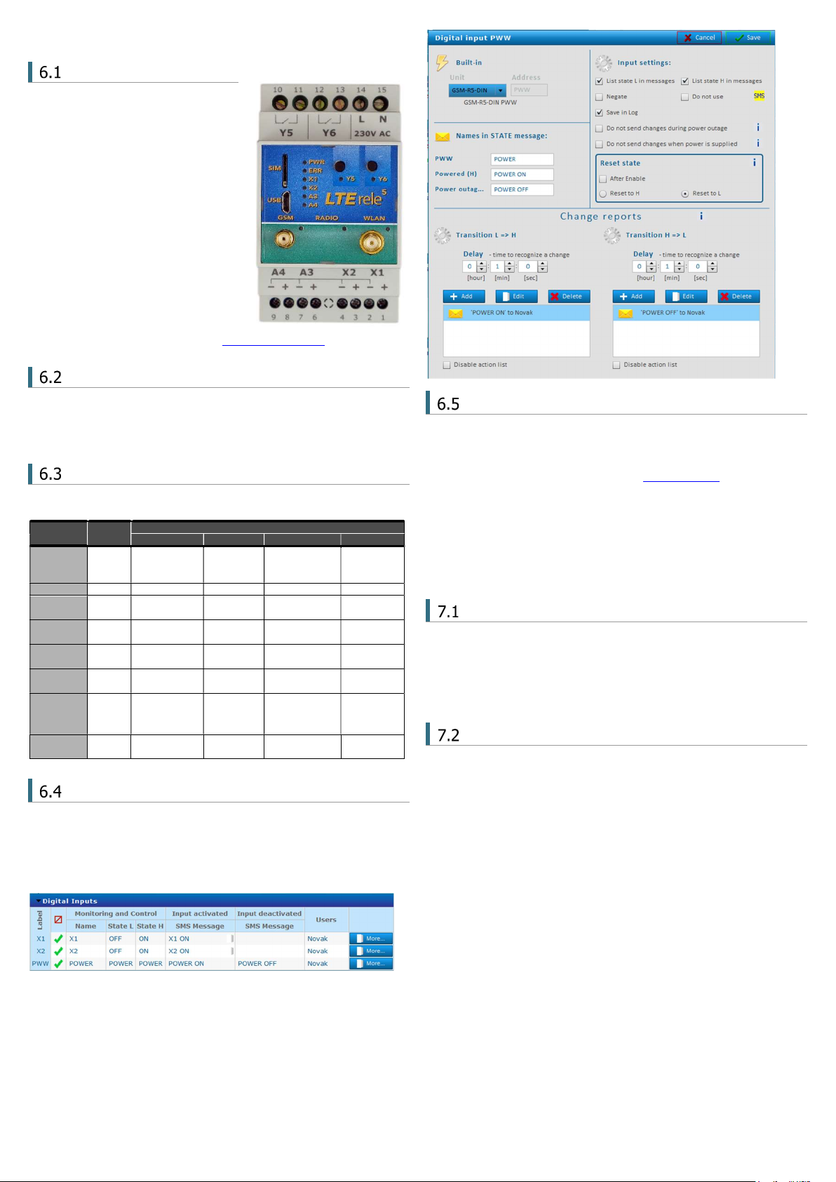
In case of failure of the main power supply, the device can send an SMS message. The
settings are made in SeaConfigurator – the power supply is listed on the Digital
inputs tab under the name PWW.
Antennas
LTE rele
5
is supplied with an external WiFi self-adhesive antenna and an external GSM
self-adhesive antenna GSM-ANT05S with 2,5dB gain. It is not recommended to put
this type of GSM antenna on metal surface (the signal quality will degrade). If a
LTE
rele5
is used in area with a low GSM signal, it’s possible to use another type of the
antenna with higher gain. See other antennas on www.seapraha.cz.
7. Configuration
Configuration of the
LTE rele
5
can be made in several ways.
Default Factory Configuration
When outputs Y5 or Y6 are switched on/off, the
LTE rele
5
sends an SMS message to
the main user (to the telephone number from which it received the first valid command).
The input signal must be stable for certain time (approx. 1 sec) to avoid sending
unwanted SMS messages in case of interference on the input.
Temperature regulators are set up so that the OUTPUT Y5 is regulated by temperature
sensor on INPUT A3 and OUTPUT Y6 from the temperature sensor on INPUT A4.
Configuration using PC via USB
The configuration (parameter setting) can be done using program SeaConfigurator.
For connection to PC device has micro USB connector.
E.g.
LTE rele5
can be set to inform of the 230V AC power failure or restoration via SMS
or by ringing.
LED COLOR
Meaning
Off On Blink 1 per 3s 1:1
PWR green device is off
powered
from
230 V AC
powered from
backup
battery
-
ERR red no error error - -
GSM blue No GSM
signal - registered Searching
GSM net
RADIO blue Bluetooth is
non-active
Bluetooth
is active
WLAN blue WiFi is not
available
Connected
to WiFi Searching
WiFi
X1
X2 green Input is not
activated
Input is
activated - -
A3
A4
green - - - -
Y5
Y6 yellow Output is
disconnected
Output is
connected - -

LTE-R5-DINW_User_Manual_EN_v1-04.docx Strana 3 z 8
Change of configuration via SMS
Some parameters of
LTE rele
5
can be configured via SMS:
List of configuration SMS commands:
Caution
When configuring via SMS it is important to understand that changing
parameters will cause mismatch with configuration saved in PC.
Parameters which can be changed/set via SMS are marked in SeaConfigurator with a
yellow “SMS” field (see picture below). By clicking it, a window with a hint will appear.
8. Control
Output control by “ringing”
LTE rele
5
is set by the manufacturer to switch ON an OUTPUT Y6 for 4 seconds when
any user from the list of users calls to
LTE rele
5
phone number. This pulse is useful for
an opening of an entry gate. Test this function by a call to
LTE rele
5
from your mobile
phone (it’s important to send a valid command SMS to
LTE rele
5
from your mobile
phone if have inserted a “new” SIM card to
LTE rele
5
).
LTE rele
5
rejects a call and at the same time generates a pulse on an OUTPUT Y6.
Remote control of
LTE rele5
via SMS
LTE rele
5
is controlled via SMS of the GMS network. Text SMS are in form:
<PASSWORD> <COMMAND> [<COMMAND >]
Password (access code)
Password is a main security item for
LTE rele
5
control. Command SMS are accepted
from any phone number. It means anybody who knows the password and the phone
number can control the
LTE rele
5
. The password is a string of digits (1 to 20) which
must be on the beginning of any command SMS. Otherwise the SMS will be ignored. A
text before the password is automatically ignored. It is useful when command SMS are
sent from Internet GSM gates. The password can be changed using SEAConfigurator on
the tab General or by a configuration SMS message.
Default password set up by manufacturer:
1234
Command
This part of a message specifies a requested action. See the following table for available
commands.
LTE rele5
commands are not a case sensitive, it’s possible to use upper
letters as well as lower letters.
Each command is preceded by Yx, where x is the number of controlled output. If output
is not specified, the OUTPUT (Y5) is used as default. Commands ON and Y5 ON and
Y5ON has the same meaning.
It´s possible to use multiple commands in one message separated by a space.
E.g.
1234 ON … switch on device connected to output Y5
1234 Y5 ON … switch on device connected to output Y5
1234 Y6 OFF … switch off device connected to output Y6
1234 Y6 PULSE 5 … an OUTPUT Y6 will be switched on and then after 5 seconds
will be switched off (Notes: if an output is already switched on, it will be just switched
off after 5 seconds)
1234 Y6 reg 5 … requested temperature for the function temperature regulation
of OUTPUT Y6 will be set to + 5°C
Using multiple commands in one SMS message can look like this:
1234 Y5 OFF Y6 REG 25 … switch off output Y5 and sets temperature regulation
on output Y6 to 25 °C according to temperature sensor on input A3.
Confirmation
If a command message contains a valid password (access code) the
LTE rele
5
returns
a confirmation message which informs if a command was accepted (see chapter Status
SMS). If you don’t want a confirmation message (e. g. when sending a command SMS
from the Internet GSM gates) add a command “NOBACK”.
E.g.
1234 Y5 ON NOBACK …
LTE rele
5
will switch on device on output Y5 and
will not send message back.
Command Parameter
Meaning
!FACTORY -
All parameters are setup to factory default.
E.g. Reset to factory default in
LTE rele
5
(all custom
configuration will be deleted.).
1234 !FACTORY
USER ADD Phone
number
Create new user with specified phone number. If phone
number is already in the list an error is indicated. If
phone number already exists and user is “disabled”, User
is enabled and no error is indicated.
E.g. 1234 USER ADD +420123456789
USER DIS Phone
number
A “disabled” flag for the user is set. If and user is not in
the list an error is indicated.
E.g. Disable user with phone number +420123456789
from controlling device by ringing.
E.g. 1234 USER DIS +420123456789
USER
CHANGE
Phone
number
Changes phone number on different one. If fist phone
number isn´t there or second one is already int the list
an error is indicated.
E.g. Change user´s phone number from +420111111111
to +420222222222
1234 USER
CHANGE+420111111111+420222222222
CODE ADD Password
New user with specified password is added (password
max. 20 digits). If the password already exists an error
is indicated. If the password already exists and the user
is disabled, the user is activated and no error is
indicated.
E.g. Add new user with password 9876
1234 CODE ADD 9876
CODE DIS Password
A “disabled” flag for the code is set. If the user is not in
the list an error is indicated.
E.g. Disable user with password 9876 from controlling
device.
1234 CODE DIS 9876
CODE
CHANGE Password
The first password in the list is replaced by the second
password. If the first password does not exist in the list
or the second is already in the list an error is indicated.
E.g. Change password from 1234 to 9876
1234 CODE CHANGE 1234 9876
X1 !DIS !DIS
!ENA
Disable/enable changes from input/output.
(Typical use is when error on input is occurred, on which
LTE rele
5
reacts by sending big amount of SMS
messages.)
E.g.
1234 X1 !DIS … disables changes from input X1
1234 X2 !ENA … enables changes from input X2
REGISTER number
Registration of sender of SMS messages as authorized
person who can change settings of
LTE rele
5
via GPRS
connection.
Identification number has to match with number
allocated from SeaConfigurator.
E.g.
1234 REGISTER 987654
Command Parameter
Meaning
Y5 ON - Switch on output Y5 (Y6 ON switch on output
Y6)
ON - If no output is specified, switch on output Y5
Y5 OFF - Switch off output Y5 (Y6 OFF switch off output
Y6)
OFF - If no output is specified, switch off output Y5
Y5 PULSE
Y5 RESET
5
Switch on output Y5 for 5 seconds creating pulse.
Reset output Y5 for 5 seconds.
PULSE
RESET
If no output is specified, create 5 sec pulse on
output Y5
If no output is specified, reset output Y5
REG
0 to 55
Setting of requested temperature and starts
regulation mode. Request of status SMS (state of
inputs, outputs, temperatures, signal quality and
credit).
STATE - Request of status SMS (state of inputs, outputs,
temperatures, signal quality and credit).
Command Meaning
NOBACK No confirmation SMS will be sent
LTE-R5-DINW_User_Manual_EN_v1-04.docx Strana 4 z 8
Local control of outputs
LTE rele
5
has 2 push buttons for local control of outputs Y5 a Y6 (see chapter 5.2).
Status SMS message
Whenever the command SMS contains valid password the
LTE rele
5
send back Status
message.
Note: if value of parameter Signal is ??, -- or== It´s an error.
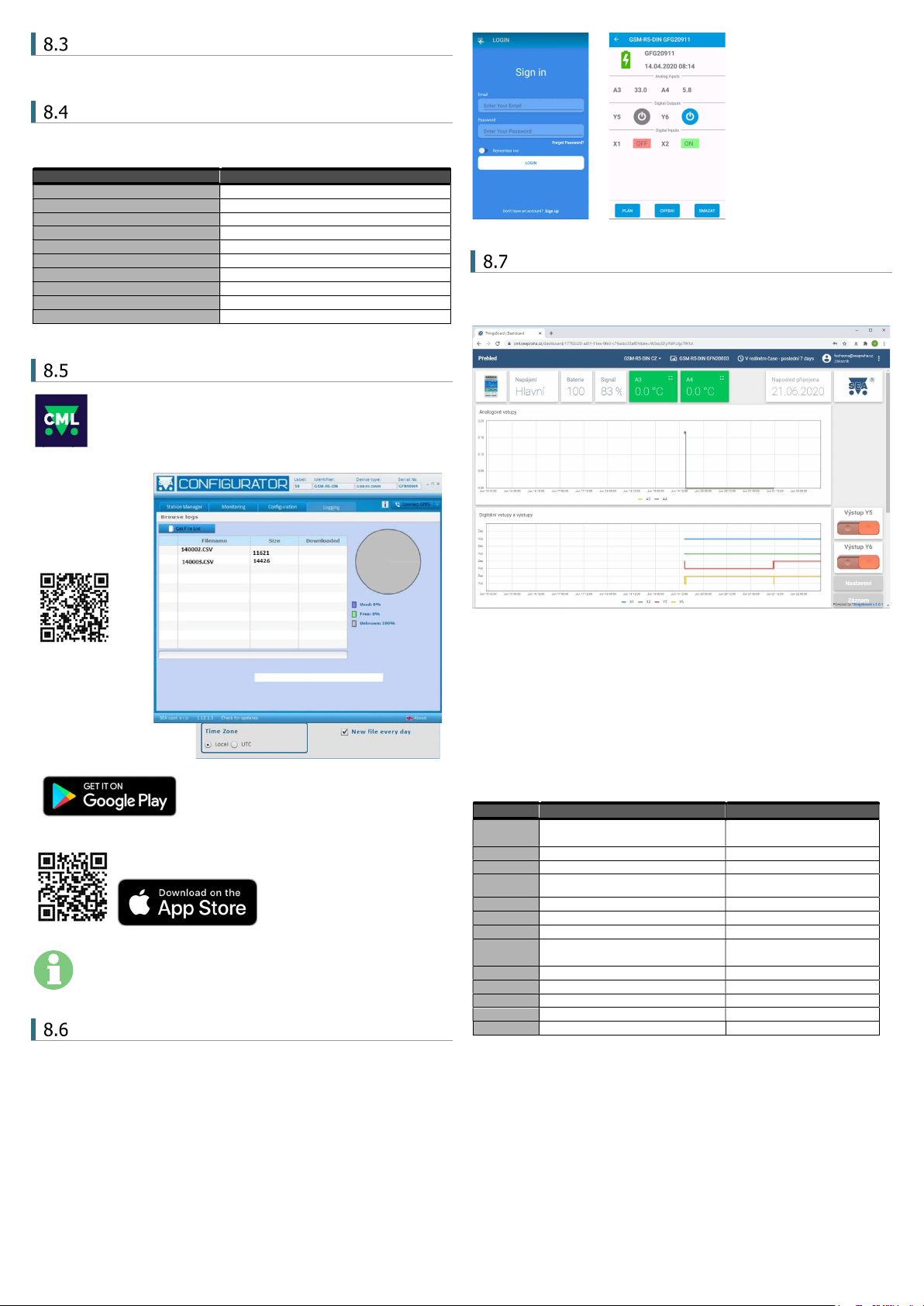
Control using CML (for Smart phones)
This application can use smartphones with Android or iOS. Application
makes easier control of
LTE rele
5
and state monitoring. You can download
this application from Google Play or Apple Store for free, type into search
„CML SEA“. After installing the application, make the first registration,
take a photo of the QR code of the device into the “paring code”. The QR code you find
in the
LTE rele
5
package
.
The device is paired to your WiFi network via Bluetooth, so it
is necessary to have it
switched ON on your
phone. Then press the
“Pair Wifi via
Bluetooth” button in
CML and fill in the
required data.
WARNING: For the functionality of the CML application, it is
necessary to have an activated data tariff on the SIM card, which
is inserted in the device. Transferred data can be charged by the
operator according to the tariff agreed by you.
Enable CML
The CML function must be switched on in the GSM-Configurator in „Station settings“,
press the edit button in the „CML“ line and check „Enable“ in the CML window.
On-line data on a website
You can monitor the measured values, including the history, and display them clearly
on the cml.seapraha.cz website. You can also control the outputs or set up e-mails
with alarm messages directly from the website.
9. Datalogger
LTE rele
5
can save (log) detailed information about device´s actions. Saving period of
analog values is set up in SeaConfigurator in settings of the station. Saved log can
be used for analyzing activity of device. User can set up which information will be saved
to log file during configuration of
LTE-R5-DINW
via SeaConfigurator.
Is possible to save information about input/output signals or received/send SMS
messages. File type of log file is .csv (= Comma Separated Values). Name of log file is
derived from actual date (data.csv).
There are two types of log records: periodic and event. Event record contains actual
analog values.
label Meaning Example
Time Local
Local date and time when event
appears.
2020-04-01 15:32:14
type *1) Type of saved record (number) 1
type2 Type of saved record (word) period
phone/
event Phone number/ Event +420123456789
text/ action
Text of SMS message / Action LTE-R5-DINW: input is on.
A3[°C] *3) State of analog input A1 22,6
Y5 State of output Y5 0
Y5. cmd *2) Output Y5 is regulated to value
28,0 (current value is 22,6)
,R22.6/28.0
X1 State of input X1 1
AP Analog input "power" [V] 14,4
PWW Digital input power 1
GSM. cell Information about BTS 23002F,0404,047A_006E
GSM. sig Current GSM signal strength [%] 35
*1) type (type2) - type of record
1 (perio) - periodical record specified by time
2 (event) - record about state change of input/output
3 (insms) - received SMS
4 (outsms) - sent SMS
5 (incall) - received SMS
6 (outcall) - sent SMS
7 (debug) - debug informations (only reason for restart)
8 (talk) - play audio (not included)
9 (fault) - error
32(firmware) - uploading firmware
*3) A1:
Example of status SMS message Meaning
Base station: Y5 ON OK Command confirmation: Y5 is switched on.
X1=ON State of input number 1
X2=OFF State of input number 2
A3=28'C State of input number 3
A4=5.0V State of input number 4
Y5=ON State of output number 1
Y6=OFF State of output number 2
Power=good Power state (from battery or power supply)
Battery=100% State of battery charge
Signal=58% State of GSM Signal

LTE-R5-DINW_User_Manual_EN_v1-04.docx Strana 5 z 8
O … disconnected;
Z … short circuit;
? … unknown (Device is not communicating after turning on.)
[°C] ... unit of measurement
*2) Y.cmd:
,R22.6/28.0 - R means regulation current temperature is 22,6°C
/ required temperature is28,0°C
- P is pulse
- Q is reset
10. Warranty
General warranty period is 12 months after purchase, when eventual
malfunction device will be repaired free of charge in SEA company
while shipping to SEA is paid by customer and SEA pays for shipping
back to customer. For SW there is 24 months warranty under
following conditions:
Both CPU and PC software is sold “as is”. The software was created
by the best software engineers in SEA and was carefully tested both
in SEA and also by SEA customers using GSM applications products
made in SEA. In spite of making all possible to get error free software it can happen,
that the software in CPU or PC programming SW or their mutual interaction has some
error under some specific conditions. If such error is found and the description of the
problem including configuration file is sent by E-mail to SEA ltd., the error is removed
free of charge and SEA will send new SW by E-mail to customer.
SEA ltd. has NO RESPONSIBILITY for any damage, lost, costs and any other problems
direct or inducted, caused by such SW error, by eventual device malfunction from any
reason or by undelivered SMS from the device.
The manufacturer, seller or installation company is not responsible for the amount of
transferred data, connections, telephone calls, sent SMS, MMS, or other charged services
of GSM network operators and is not responsible for the amount of fees for GSM network
operators of the installed SIM card. Nor is it liable for the energy consumed by the
equipment it controls or for any other damage.
CE Declaration of conformity
in accordance with the Radio and Telecommunications Terminal Equipment Directive 1999/5/EC (R&TTE) and Directive
2011/65/EU (ROHS).
We SEA, spol. s r.o., Dolnoměcholupská 1537/21, CZ 102 00 Praha 10, Czech Republic, ID: 47117931 (manufacturer)
declare under our sole responsibility, that product device for remote control and monitoring type LTE-R5-DINW
is in conformity with the following standards:
health and safety: EN 62368-1:2004
EMC: EN 61326-1:2013
radio frequency: EN 301 511 v12.5.1, EN 301 489-7 v1.3.1
ROHS: EN 50581:2012
The last two digits of year in which the CE marking was affixed:
22
Place of issue: Praha Name: Ing. Vladimír Rosůlek
Date of issue: 30.5.2022 Grade: Technical director

LTE-R5-DINW_User_Manual_EN_v1-04.docx Strana 6 z 8
11. Examples of connection
Heating control
Centralized control of loads connected to switchboard is typical for electric heating. Electronic ripple control causes disconnection of electrical heating in time of high tariffE.
This wiring controls power for electric heater. An electrician would said, that outputs of
LTE rele
5
are connected into series with centralized control of loads. Outputs of
LTE rele
5
controls contactors and they control heater and boiler.
On the picture you can see one phase contactors, but three phase contactors can be used as well. – But those could require bigger current through coil. Make sure, that you don´t
exceed allowed current on outputs of
LTE rele
5 (see Technical specifications).
This wiring works like that. Temperature sensor A3 is able to regulate (switch on/off) output V3. Switching output V3 on/off by temperature sensor A3 is set in factory configuration.
In SeaConfigurator in settings of output Y5 select freezing temperature (set on 5°C and mark “enabled”).And thermoregulator in room set on comfortable temperature (e.g.
22°C). Heater control wirelessly through commands 1234 Y5 ON (heat up to 22°C) a 1234 Y5 OFF (turn off heater). If temperature drops below 5°C Output Y5 will be switched on
and regulates to nonfreezing temperature. If you have enabled heating to freezing temperature in SeaConfigurator, you can´t switch off heating by command 1234 Y5 OFF. If
you need to switch off the heater is possible to disable output by command 1234 Y5 !DIS and then enable again by command 1234 Y5 !EN.
If you want to heat up on higher temperature (for example on 15°C) than is freezing temperature, you can use command 1234 TEPL 15. If selected temperature in command will
be higher (e.g. 25°C) than temperature set on thermoregulator , heater will be turned on until it reaches temperature set on thermoregulator (for example on 22°C).
Output Y6 is possible to use for same circuit with heater. (By factory settings output Y4 is regulated by sensor A4.) or it can be used for boiler, eventually for gate control via ringing
etc.
Temperature alarm setting is independent on temperature regulation (temperature alarm is setting temperature bounds in SeaConfigurator, it can send SMS message if
temperature drops or exceeds selected temperature).
L N PE
BOILER
230V AC
PE
N
L
CIRCUIT
BREAKER
CONTACTOR
I
O
AUTO
I
O
CONTACTOR
I
O
AUTO
ELECTRONIC
RIPPLE
CONTROL
SWITCHBOARD
L N PE
HEATING
ROOM
THERMORE
GULATOR
Switch ON
the heating
via room
thermoregulator
ROOM
Temp.
sensor
22°C
LN PE

LTE-R5-DINW_User_Manual_EN_v1-04.docx Strana 7 z 8
Comfortable temperature control
If you need regulate higher temperature than temperature set on thermoregulator. You can use different wiring, where you disable thermoregulator by output Y6.
Command 1234 Y6 OFF will enable thermoregulator A3 to regulate heater. Heater will heat until it reaches selected temperature. Those commands can be sent in one SMS message
simultaneously.
Regulation to 25°C 1234 Y6 OFF Y5 TEPL 25 ( thermoregulator is disabled)
Regulation to 22°C 1234 Y6 ON Y5 OFF ( thermoregulator is set to 22°C)
Regulation to 7°C 1234 TEPL 7 ( thermoregulator is disabled)
Digital inputs
Example of connection of inputs X1 and X2 as contact status detector:
If you need to monitor a potential free contacts (for example magnetic contacts of the alarm circuit or relay contacts), connect them
directly to inputs X1 and X2.
230VAC
PE
N
L
CIRCUIT
BREAKER
CONTACTOR
I
O
AUTO
I
O
SWITCHBOARD
LNPE
HEATING
ROOM
TEMP.
SENSOR
22°C
LN PE
Switch ON
the heating
via room
thermoregulator
ROOM
THERMORE
GULATOR
ELECTRONIC
RIPPLE
CONTROL
LTE-R5-DINW_User_Manual_EN_v1-04.docx Strana 8 z 8
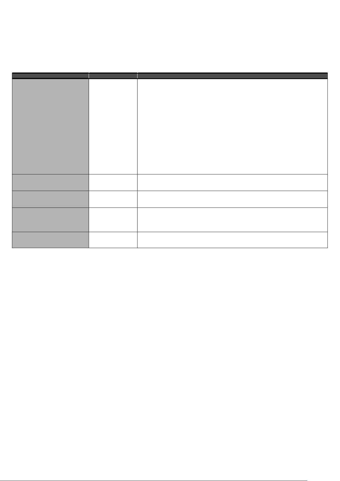
12. Frequently Asked Questions (FAQ)
What is necessary to use the
LTE rele
5:
Good quality GSM signal in a place where
LTE rele5
will be used (at least 2 bars on your mobile phone)
Sufficient credit on a pre-paid SIM card
No phone call redirection
The user has to know to operate his mobile phone (PIN usage deactivation)
Note: Users who knows to operate older version of GSM RELAY version 2 can use older SMS command form: E.g. 1234 ON3 OFF4
Problem description Possible reason Solution
LED GSM (blue ) flashes 1:1 (slow)
LED GSM (blue) is off (dark)
LED ERROR (red) is on
(lights permanently)
SIM card is not
functional
New SIM card is not
activated yet
Low credit on a pre-paid
SIM card
Weak/poor GSM signal
Test the SIM card in your mobile phone. Try to make a call and receive a call from another mobile
phone. Try to send a receive SMS message.
Switch off using PIN on a SIM card. Cancel all call redirection for a SIM card. (Ask your mobile operator
for help if necessary).
New SIM card has to be activated. (Ask your mobile operator for help if necessary).
Check credit on a pre-paid SIM card.
(Ask your mobile operator for help if necessary).
Test the SIM card in your mobile phone. The mobile phone should show the signal level at least 2 bars.
The pulse on an output is not generated
based on incoming ring signal (e. g. for a
gate opening)
The incoming phone
calls for a SIM card are
redirected
Cancel all phone call redirections for the SIM card
Sometimes pulse generation on output via
“ringing” doesn´t work (e.g. gate opening)
Permanent GPRS
connection (e.g. GPRS
WATCH)
At some GSM providers phenomenon appears, that device connected to GPRS sometimes appears as
unavailable.
GSM rele5
sends SMS message, that
„connection to configura
tion server failed:
error 5/0 0,1,1“
GPRS connection was
interrupted, when
GSM rele5
ring user,
who doesn´t react for
too long.
Restore GPRS connection from SeaConfigurator.
During ringing user from
GSM rele5
decline call in shortest time possible.
The temperature from an external
temperature sensor is wrong. Too long
lines to an external temperature sensor.
Too long lines to an
external temperature
sensor
The accuracy of temperature depends on a line length to an external temperature sensor (16 Ohms
means 1°C). Use thicker wires to temperature sensor.
Other SEA Praha Relay manuals


