SEA Praha GSM-R5-ZAS Series User manual

gsm-r5-zas_user_manual en v2-06 strana 1 / 5
GSM-R5-ZAS, GSM-R5-ZAS-xxx
1. Introduction
The GSM-R5-ZAS (hereinafter referred to as
GSM relay5
) is relay controlled remotely
by SMS messages over GSM network. Other features include, for example, remote
temperature control, „ring-out“control of the appliance, or an additional input for event
and alarm reporting. The device remembers its status and parameters, so it doesn’t
have to be setup after every power-on.
GSM relay5
is equipped with a removable
terminal block located on the side of the device designed to connect one analog input
for temperature or logic value measurement.
GSM relay5
is tailored for easy
connection, installation and control. It is connected to the existing power supply of the
appliance. This supply can then be switched on, off, temporarily disconnected or used
to automatically control the heating to the desired temperature. The state of the
connected inputs can be detected by SMS messages or the
GSM relay5
can be set up
to send SMS messages whenever state of the input is changed. In addition to the basic
version with the terminal block on the side there are also variants with additional
features.
1) Plug for insertion into the mains 230 VAC.
2) Socket 230 VAC.for connecting the
controlled device (10 A, 2300 W)
3) ON/OFF (yellow LED + button)
4) PWR (green LED for indication of power)
5) Micro USB for configuration
6) SIM card holder
7) Removable terminal for connecting
external temperature sensor (the sensor
must be ordered separately).
8) GSM (blue LED for indication of
connection to GSM network)
For the basic variation it is possible to
order the connector for the external
antenna GSM-R5-ANT.
9) For other variants, there is 6pin terminal
form the underside. See chapter
„Variations with EXTENSIONS“.
2. Commercial packaging
1ks GSM relay5
1ks 2 pin connector, pitch 3,81mm
1ks 6 pin connector, pitch 3,81mm ...only variants with extensions.
1ks Articulated antenna 2dB...............only variants with additional features.
1ks screwdriver 2mm
3. Recommended accessories
GSM-C-T2 semiconductor temperature sensor in plastic
enclosure, 1m cable.
4. First time startup
1. For proper device operation a SIM card is required. The SIM card have to be
functional, activated and with disabled PIN code. Prepaid credit cards must have
nonzero credit.
2. Insert the card into the Holder. Push the card inside, until you hear mechanical
„click“.
3. Now you can insert the device into the mains. If the socket is OK green LED PWR
will turn on.
4. Now connect your electrical appliance into the GSM relay5.
5. First press the button on the GSM relay5. The relay will change its state and yellow
LED ON/OFF should light up.
6. Send SMS message „1234 OFF“ to the SIM card you’ve inserted into the GSM
relay5. This will turn off the socket and add your telephone number into its list
under name MASTER. The password 1234 can be later changed. The device will
execute … to anyone with correct password.
7. ???
8. Test the temperature control, for example at 25° C. The socket will switch on and
off according to the temperature input A1. Connect the temperature sensor to the
temperature input A1 and send the SMS 1234 TEMP 25. The control is terminated
by a 1234 OFF message or by pressing the ON / OFF button.
9. Factory setting of GSM relay5 can be restored by sending a 1234 !FACTORY
message. If you made a backup configuration of SeaConfigurator settings (Settings
tab -> Files button -> File option), you can restore your settings from this backup
(Settings tab -> Files button -> File option).
10. The names of the inputs, outputs (their states) and the command names can be
modified according to your ideas using the SeaConfigurator configuration
software. This configuration program can be downloaded free of charge from
www.seapraha.cz (enter the word „Configurator“in the search) and install it on
your PC.
5. Technical specification
Parameter
Symbol
MIN.
TYP.
MAX.
Unit
Dimensions
Width
W
65
mm
Length
L
140
mm
Depth
D
95
mm
Power Supply
Voltage
PWR
100
230
250
VAC.
Consumption
1
3
W
Battery
Li-ION
Operation after power failure
20
hours
Digital outputs
Mains socket - Y2 (switched relay)
Voltage
VOUT
According to the supply voltage
Max. current -
Resistive load
IOUT
10
A
Analog input
External (removable) temperature sensor GSM-C-T2
distinction 0,1°C. accuracy in range 0 to 30 °C … 1 °C
Temperature
measurement
A1
-30
+55
°C
Temperature
Storage
tSTG
-40
+85
°C
Operational
Ta
-20
+40
°C
Humidity
RVmax
90
%
GSM relay5
is intended for indoor use!
For basic variant, it is possible to order Li-ION accumulator for reporting of power
failure..... GSM-R5-BAT.
For more specification see chapter „Versions with extensions“.
6. Hardware
6.1 Connectors
GSM relay5
has a plug, that plugs into the mains and a switched socket for connection
of external appliance. the on / off switching is done by built-in relay.
It is possible to connect one external temperature sensor KTY81-210. The length of the
wires to the connected external temperature sensor is not limited, but it should be
considered that the longer conductor has a certain resistance that affects the measured
value. 16 Ω equals approximately 1 ° C.
6.2 LED diodes
LED
Color
Meaning
6.3 SIM card holder, button, USB and antenna
Insert SIM Card according to the picture. Push the card inside, until you hear mechanical
„click“.
Press the ON / OFF button briefly to switch on or off the appliance connected in the
socket. If the GSM relay5is not powered and the battery is installed, the GSM relay5
switches off by pressing for a long time (>= 5 seconds).
Micro USB connector is for offline configuration with SeaConfigurator.
If the device is equipped with an antenna connector, the antenna is connected via the
SMA connector. The device is fitted with a SMA female connector, the connected
antenna must have a male SMA connector. The impedance is 50 Ω. If there is no
connector, the device is fitted with an internal antenna.
6.4 Battery
GSM relay5
It can be equipped with a 3.7 V stand-by Li-Ion battery. After power failure,
the device is able to operate in normal mode for about a day (the duration depends on
how much it is used).
7. Configuration
GSM relay5
is configured with SeaConfigurator either via the USB connector (microUSB
cable no. HW-11.02) or through the GPRS connection. This configuration program can
be downloaded for free from http://www.seapraha.cz (search for „Configurator“) and
install it on your PC.
GSM relay5
is shipped with a factory configuration that meets the most common
requirements, so it is possible to use the device even without SeaConfigurator. Simply
send the first SMS from the main user's phone number under the “First time startup”
chapter.
Some parameters be changed via SMS, see chapter „Command List“.
GSM
Blue
Indicates device status. Possible states are:
Flashing 1:1 … the device is setting up
Short flash 1x in 4 sec … device is in operation.
PWR
Green
It is permanently lit when powered from an external
source.
Flashes while running on the internal battery.
ON/OFF
socket (Y2)
Yellow
Shines continuously when the socket is switched ON
Before inserting the SIM card into the GSM relay5device, you must
first disable the "PIN code“ !
Insert activated SIM card into any working phone and disable PIN code. In
most mobile phone devices this option is under Settings -> Security.
3
1
2
5
6
7
8
4
gsm-r5-zas_user_manual en v2-06 strana 2 / 5
8. Control
8.1 Ring control
GSM relay5
comes from the manufacturer set to turn on the socket for a pre-set time.
This can be used, for example, to switch the heaters on. Since the factory default is 4
seconds, it is best to change it with SMS, for example, in the form of 1234 PULSE
14400. To test this feature call
GSM relay5
from your telephone (The number must
be in the list).
GSM relay5
rejects the call, and at the same time ensures that the
socket is switched on for 14400 seconds (i.e. 4 hours).
8.2 Control with SMS Messages
GSM relay5
is controlled with SMS messages from GSM network. SMS must be in the
form:
PASSWORD space COMMAND space COMMAND .....
Commands are separated by a space and are not case sensitive.
Password
Password is the main security element in control of
GSM relay5
. SMS with commands
will be accepted from anyone who knows the password. The password is a string of
digits (it can be any length from 1 to 20), Which the SMS message must contain, or
else it’s ignored. Because the text before the password is ignored, SMS messages can
also be sent from the SMS gateways. We recommend changing the password to
something different. Password can be changed either through SeaConfigurator or with
SMS message.
Default password is:
1234
Command
This part of the message defines the desired action of the device. Multiple commands
separated by a space can be inserted into one SMS message.
The command can consist of multiple parts. For example, when it comes to output, it
consists of its name „Y2“and an action (e.g. ON, OFF, etc.). If the naming of the output
is not specified, the output with the lowest sequence number is used (for the GSM
relay5it is the socket). The ON and Y2 ON commands are therefore equivalent.
In addition, a parameter (e.g. pulse length, required temperature, etc.) may be given
behind the command. There must be space between the command and its parameter.
Most used commands (more in chapter “List of commands“)
Examples:
1234 ON …Turns the socket ON (output Y2)
1234 OFF …Turns the socket OFF (output Y2)
1234 TEMP 20 …Sets the desired temperature to 20 ° C
1234 PULSE 43200 …Turns the socket ON and after 12 hours (=43200 seconds) will
turn the socket back OFF.
Note : if there was ongoing regulation it will be resumed after the period ends.
1234 RESET 43200 … Turns the socket OFF and after 12 hours (=43200 seconds)
will turn the socket back ON
Confirmation
If
control message
contains valid password,
GSM relay5
will respond with message
about success or fail of requested action. If this behavior is not desired, it is possible to
disable the reply with NOBACK command.
Example:
1234 ON NOBACK …
GSM relay5
will turn the socket on, but won’t send any
confirmation message
8.3 Attached report status
If you send a command containing a valid password, GSM relay5 will always respond to
the execution of the command.
Example: 1234 ON
If it is not disabled the STATE message will be appended to the message about
execution. State message contains following information:
Note: If any input or output is disabled (by SMS or by SeaConfigurator), it won’t be
mentioned in STATE message.
8.4 Macros
Built-in macros with variables
You can use macros listed in the macro list in the event text. These macros are used
when you want to create your own status message. In this case, be sure to cancel the
„state message reply“option in the „General Settings“section.
Examples:
SMS with text: „Temperature is low, [Y2].“ Will be sent as „Temperature is low,
Y2=ZAP.“
SMS with text „output is ON([A1N] is [A1V]).“ Will be sent as „output is ON
(TEMPERATURE is 18,1 °C).“, where „input name“ A1 is TEMPERATURE and „units“ are
in °C.
Macros in incoming SMS
If you need to simplify a regular repeating command or a summary of commands
(including even the parameters), create a macro. For example, create a macro: „FIRE“
with text „Y2 TEMP 25“. If you then send an SMS with the text „FIRE“, output Y2 (OUT)
will be regulated by the temp. Sensors at 25 ° C.
Macros in sent SMS
For example, you can define the macro „N1“with the text „My Station is Best in the
World“to help you work on creating text in sent SMS. Then just use the text „[N1]“in
the outgoing SMS.
Note.: Macros must always be in square brackets
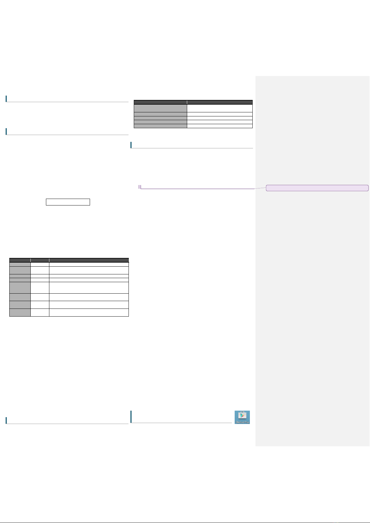
8.5 Control through the application
SeaControl
for OS android
For control and monitoring of
GSM relay5
it’s possible to use application for device
with OS Android, which is available for FREE. In your smartphone start Google Play and
Command
Parameter
Meaning
Y2 ON
-
Turns the socket ON (output Y2).
ON
-
If sent without parameters, the socket will be turned ON
(output Y2).
Y2 OFF
-
Turns OFF Y2 (socket).
OFF
-
Turns the socket OFF (output Y2).
Y2 PULSE
Y2 RESET
0 to
999999
Parameter is in seconds.
Pulse command will switch the socket temporarily ON.
Reset will switch the socket OFF for period of time
PULSE
RESET
It will make a pulse or a reset for the same period as
previous command. Factory default is 4 seconds.
TEMP
0 to 55
Sets the desired temperature for regulation. Value is in
°C.
STATE
-
Request for message with information about state of
outputs, inputs signal strength and remaining credit.
STATE message example
Info explanation
GSM RELAY5: VYP ACCEPTED
Command confirmation: outlet (Y2) will be
turned off.
outlet=OFF
State of outlet (Y2)...OFF.
Temperature=28'C
Current temperature of sensor A1.
Power=Powered
State of power(from battery or from source).
sig=58%
State of GSM signal is 58%.
Okomentoval(a): [MV1]: Tady se skončilo
gsm-r5-zas_user_manual en v2-06 strana 3 / 5
search for „
SeaControl“
. Application communicates to
GSM relay5
with SMS
messages. Application control is intuitive - see enclosed pictures..
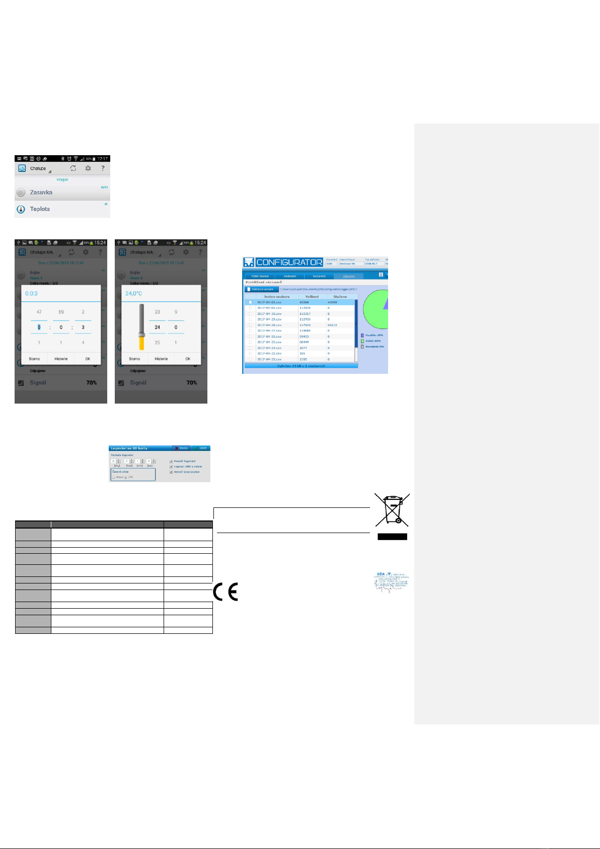
Switch between each device by swiping
left or right.
Pulse settings.
Reset settings
Temperature control setting, for some
time interval
In history, there are always stored two
previous values
pulse length settings: setting temperature to control:
9. Data logger
GSM relay5
provides saving(logging) of detailed information about activity of the
device. Interval of saving is changed through SeaConfigurator. Saved log provides
reverse analysis of device activity. Type
of logged information are set by user
during configuration of GSM relay5. It’s
possible to save information about state
changes of each inputs and outputs,
incoming outgoing SMS. Format of log
file is .csv (= Comma Separated
Values). Name of the file is same as the day it was created(datum.csv).
Saved logs are of two types: periodic and state-change.
*1) type (type2) - Types of records
1 (period) - regular period write
2 (event) - record caused by digital input or output state change
3 (insms) - received SMS
4 (outsms) - sent SMS
5 (incall) - incoming telephone call
6 (outcall) - outgoing telephone call
7 (debug) - debug information
8 (talk) - sound playback (not used)
9 (fault) - error
32(fw) - firmware upload
*3) A1:
O … disconnected;
Z … Short circuit;
? … unknown;
[°C] ...
*2) Y.cmd:
,R22.6/28.0 - R means regulation; current temperature is 22,6°C
/ regulated temperature is 28,0°C
- P is pulse
- Q is reset
10. Warranty
Na zboží se vztahuje 24 měsíční záruka. Prosíme Vás proto o uchování Vašeho účtu a
v případě reklamace zaslání jeho kopie spolu s reklamovaným zbožím a popisem závady.
Reklamace zjevných vad, dodaného množství nebo dodávky neodpovídající objednávce
musí být uplatněna nejdéle do 5 pracovních dnů od dodání zboží. Na pozdější reklamaci
nebude brán zřetel.
Reklamačním místem je hlavní provozovna:
SEA spol. s r.o.
Dolnoměcholupská 1537/21
102 00 Praha 10, tel. 272700058
Reklamaci nelze vyřídit jako oprávněnou, pokud je závada způsobena nadměrným
opotřebením, nedodržením provozních parametrů, zásahem do zařízení nebo
neodbornou manipulací, nebo vyšší mocí (blesk, voda).
ES PROHLÁŠENÍ O SHODĚ
rádiového zařízení s ustanoveními nařízení vlády č. 426/2000Sb. ve znění pozdějších předpisů,
kterým se stanoví technické požadavky na rádiová a na telekomunikační koncová zařízení a
nařízení vlády č. 481/2012/Sb. o omezení používání některých nebezpečných látek v elektrických
a elektronických zařízeních.
My SEA, spol. s r.o., Dolnoměcholupská 1537/21, CZ 102 00 Praha 10, IČ: 47117931
(výrobce)
prohlašujeme na svou výlučnou odpovědnost, že výrobek GSM RELE5 typ GSM-R5-ZAS a GSM-R5-ZAS-xxx
je ve shodě s následujícími normami:
Bezpečnost: EN 60 950-1:2005+A1:2009 EN 60 950-1:2006+A11:2009+A1:2010+A12:2011
EMC: ETSI EN 301 489-1 ETSI EN 301 489-7 v1.3.1
rádiové parametry: EN 301 511 v 9.0.2
Poslední dvojčíslí roku, v němž bylo označení CE na výrobek umístěno:
17
Místo vydání: Praha Jméno: Ing. Mario Vejlupek
Datum vydání: 9.1.2017 Funkce: Technický ředitel
Označení
Význam
Příklad
Time Local
Local date and time
2015-04-01
15:32:14
type *1)
Type of saved log (number)
1
type2
Type of saved log (word)
perio
phone/
event
Telephone number / Event
+420123456789
text/ action
Text of SMS message / Action
GSM-R5-ZAS: Input
turned ON.
A1[°C] *3)
State of analog input A1
22,6
Y2
State of output Y2
0
Y2.cmd *2)
Output Y2 is regulated to value 28,0 (current
value is 22,6)
,R22.6/28.0
AP
Analog input "power" [V]
14,4
PWW
Digital input "power"
1
GSM.cell
Information about BTS
23002F,0404,047A_
006E
GSM.sig
GSM signal strenght [%]
35

gsm-r5-zas_user_manual en v2-06 strana 4 / 5
11. Často kladené dotazy
Popis problému
Možná příčina
Řešení
Blue LED doesn’t flash in 3 minutes
after start.
Functional SIM card is not
inserted
SIM card not activated
Insufficient GSM signal
strenght
Check the functionality of the SIM card on your mobile phone, ie call to another mobile phone, receive
phone calls, send and receive SMS messages. You also need to turn off PIN code and turn off call
forwarding.
(The necessary procedures are described in the instructions for each mobile phone or a query can be
made with a mobile operator)
The newly purchased SIM card must first be activated (the method of activating the SIM card is
determined by the mobile operator).
Check the GSM signal level at the place of installation. Most preferably your own mobile phone with the
SIM card inserted into your device. The mobile phone should be in the location where the device will be
located and the GSM signal should have at least 2 lines..
Output pulse does not work by
„ring-out“(eg opening the door)
Calls are redirected
Cancel all call forwarding for the SIM card used on your device.
The temperature measured by the
temperature sensor does not
correspond to reality
Too long lead to external
temperature sensor
Use the SeaConfigurator to calibrate the temperature value. The accuracy of the temperature
measurement is, inter alia, given by the length of the line to the connected temperature sensor. It is
true that 16 ohms represents 1 ° C. Use a stronger wire or correct the setpoint by the difference.
12. Usage examples
12.1 Remote control of heating elements
The Heating element is connected via the control relay to the OUTPUT.
This SMS message will turn ON the device:
1234 ON
This SMS message will turn OFF the device:
1234 OFF
Note.
If you changed the password 1234 to your own (e.g. 6543), then you need to send SMS with the new password: 6543 zap (6543 OFF).
12.2 Remote adjustment of temperature control
Heating element is plugged into GSM relay5.
Following SMS message will set the regulation temperature to 25°C:
1234 reg 25
If you send command „reg“ without parameters the regulated temperature will be same as was the last temperature:
1234 reg
12.3 Temperature alarm –e.g. Report about freezing
In SeaConfigurator on
Analog input A1
tab choose button
"more"
.
If you want report about temperature drop, for example, under 2°C, then change the bottom value
(factory: 5) to 2. You can also change the upper limit value (factory: 6) to for example 3 (hysteresis).
IF the temperature will drop under 2°C, then the pre-set action will happen (send SMS, command..).
When the temperature rises above the upper limit and drops below again the action will happen. You
have available three zones, so you can have three sets of commands.
TIP: If you want to receive notification only during first drop, set the upper limit high, e.g. 25°C.
13. Command list (there can be more commands in one SMS)
Command
Parameter
Example
Meaning
ZAP
1234 on
Turns on the output with the lowest sequence number and responds that the command has been
executed –if it’s not disabled in setting, then STATE message will be appended.
Y2 OFF
1234 y2 off
Turns off the output. The need to specify or not to specify the output is the same for all output
commands. In the configuration you can change the name of the output and then use that name.
off
1234 off
Turns ON the output with the lowest sequence number.
REG
TEMP
Degrees Celsius
1234 reg 25.5
Because the output name is not specified, the regulated output will be the one with the lowest
sequence number, i.e. Y2.
Y2 PULSE
seconds
1234 y2 pulse 3600
Turns ON the output with the lowest sequence number for one hour. Then turns the output off.
RESET
Seconds
1234 reset 86400
Turns OFF the output with lowest sequence number for one day. Then turns the output ON.
STATE
1234 state
Replies with message about current state of the device.
NOBACK
1234 on noback
Executes a command, but does not send a confirmation status message.
!EN
1234 !en
Enables usage of the an output with the lowest sequence number.
X3 !DIS
1234 x3 !dis
Disables output X3. That means, it will not appear in STATE messages.
!STOP
hours
1234 !stop 12
Disables reporting of all events for 12 hours. Parameter 0 (=zero) will immediately enable reporting.
USER ADD
tel. number
tel. Number
1234 user add +420123456789
+420987654321
Adds user with tel. number +420123456789 with same rights as the second number. The new user
will also receive same event messages.
USER DEL
tel. Number
1234 user del +420123456789
Deletes user with tel. Number +420123456789.
USER CHANGE
tel. number tel.
Number
1234 user change
+420123456789
+420987654321
Changes tel. Number from +420123456789 to +420987654321.
CODE ADD
Number
1234 code add 12
Adds new password 12 (password is number long 1 –20 characters).
CODE DEL
Number
1234 code del 12
Deletes password 12
CODE EDIT
Num. num.
1234 code edit 12 123456
Changes password 12 to 123456
REGISTER
number
1234 register 99887766
For GPRS connection, it’s necessary to send this SMS so the device can register to SEA spol. s.r.o.
server.
SET APN
APN name
1234 set apn „internet“
sets GPRS name APN to word “internet“
SET APNUSER
user name
1234 set apnuser „“
Sets GPRS username as an empty space.
SET APNPWD
password
1234 set apnpwd „“
Sets GPRS password as empty space.
!VERSION
1234 !version
Detailed information about the device (name, serial number, fw, etc.).
!UPDATE
1234 !update
Command for downloading new FW from SEA spol. s r.o. GPRS server; GPRS be enabled for inserted
SIM card.
!FACTORY
1234 !factory
Restores all settings back in to factory default.
gsm-r5-zas_user_manual en v2-06 strana 5 / 5
14. Variants with
EXTENSIONS
GSM relay5
on the base plate equipped with a connector for expansion. The following
variants are now created. We can create custom extensions according to your
requirements.
In these variants
GSM relay5
is equipped with built-in Li-ION battery and connector
SMA(F) for external antenna. The commercial package includes 2dB articulated antenna.
If you state, that you want to different antenna, we can exchange it for free with 5dB whip
antenna and 3m cable (GSM-ANT01S)
*) Max resistance of OPTO MOS switch is 16 Ohm
14.1
EXTENSION
GSM-R5-2A (1DIn or 1temp, 2temp, 1Dout 10Amp, 230V, ext. ant, bat)
A5 and A6.. two inputs for temperature sensor GSM-C-T2.
LED near it’s corresponding input indicates when the temperature sensor is connected.
The terminals with battery pictogram are connected to the battery.
14.2
EXTENSION
GSM-R5-2IN (1DIn or 1temp, 2DIn, 1Dout 10Amp, 230V, ext. ant, bat)
X5 a X6.. Two galvanically isolated digital inputs. They are closed when applied voltage is from 3V to 20 VDC, open when the voltage drops under 2V
LED indicates, that the corresponding input is HIGH.
The terminals with battery pictogram are connected to the battery.
14.3 14.2 EXTENSION GSM-R5-3OUT (1DIn or 1 temp, 3DOUT, 1Dout 10Amp, 230V, ext. ant, bat)
Y5 to X7.. Three galvanically isolated digital inputs.
LED indicates, that the corresponding input is HIGH.
Example command: 1234 ON Y6 OFF Y7 …. Turns Y6 ON and Y7 OFF
14.4
EXTENSION
GSM-R5-5IN (1DIn or 1temp, 5DIn, 1Dout 10Amp, 230V, ext. ant, bat)
X5 to X9.. five digital inputs with one common terminal. They are closed when applied voltage is from 3V to 20 VDC, open when the voltage drops under 2V
LED indicates, that the corresponding input is HIGH.
C is common terminal (can be either positive or negative).
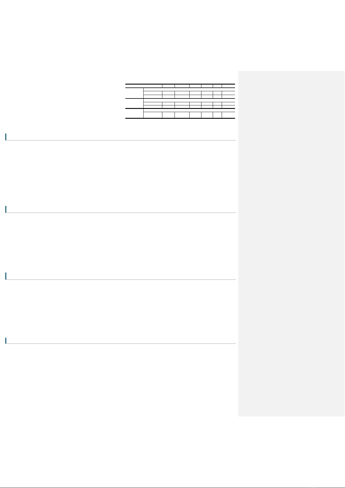
Parameter
Symbol
Podmínky
MIN.
TYP.
MAX.
Jednotka
Digital inputs
INPUT X5 až X9
Voltage
VIN
3
12
20
Vss
Current
IIN
1
4
10
mA
Digital *)
outputs
OUTPUT Y5 až Y7 – semiconducor switch OPTO-MOS
Voltage
VOUT
0
12
60
Vss
Current
IOUT
100
mA
Analog input
A1 a A2 –temperature sensor GSM-C-T2. Precision in range 0 až 30°C.......1°C
Temperature
measurement
-30
+55
°C
This manual suits for next models
1
Table of contents
Other SEA Praha Relay manuals


