Arcteq AQ-F201 User manual

AQ-F201
Overcurrent and Earth-faultrelay
Instruction manual

Table of contents
6
6
6
8
9
10
10
10
11
11
11
12
12
24
34
36
39
43
44
44
44
44
56
59
60
60
73
78
81
86
90
104
121
121
128
133
142
144
145
145
153
160
164
168
172
176
176
176
176
177
178
178
178
179
179
179
1. Manual revision notes . . . . . . . . . . . . . . . . . . . . . . . . . . . . . . . . . . . . . . . . . . . . . . . . . . . . . . . . .
1.1. Version 2 revision notes . . . . . . . . . . . . . . . . . . . . . . . . . . . . . . . . . . . . . . . . . . . . . . . . . . . .
1.2. Version 1 revision notes . . . . . . . . . . . . . . . . . . . . . . . . . . . . . . . . . . . . . . . . . . . . . . . . . . . .
2. Abbreviations . . . . . . . . . . . . . . . . . . . . . . . . . . . . . . . . . . . . . . . . . . . . . . . . . . . . . . . . . . . . . . .
3. General . . . . . . . . . . . . . . . . . . . . . . . . . . . . . . . . . . . . . . . . . . . . . . . . . . . . . . . . . . . . . . . . . . . .
4. IED user interface . . . . . . . . . . . . . . . . . . . . . . . . . . . . . . . . . . . . . . . . . . . . . . . . . . . . . . . . . . .
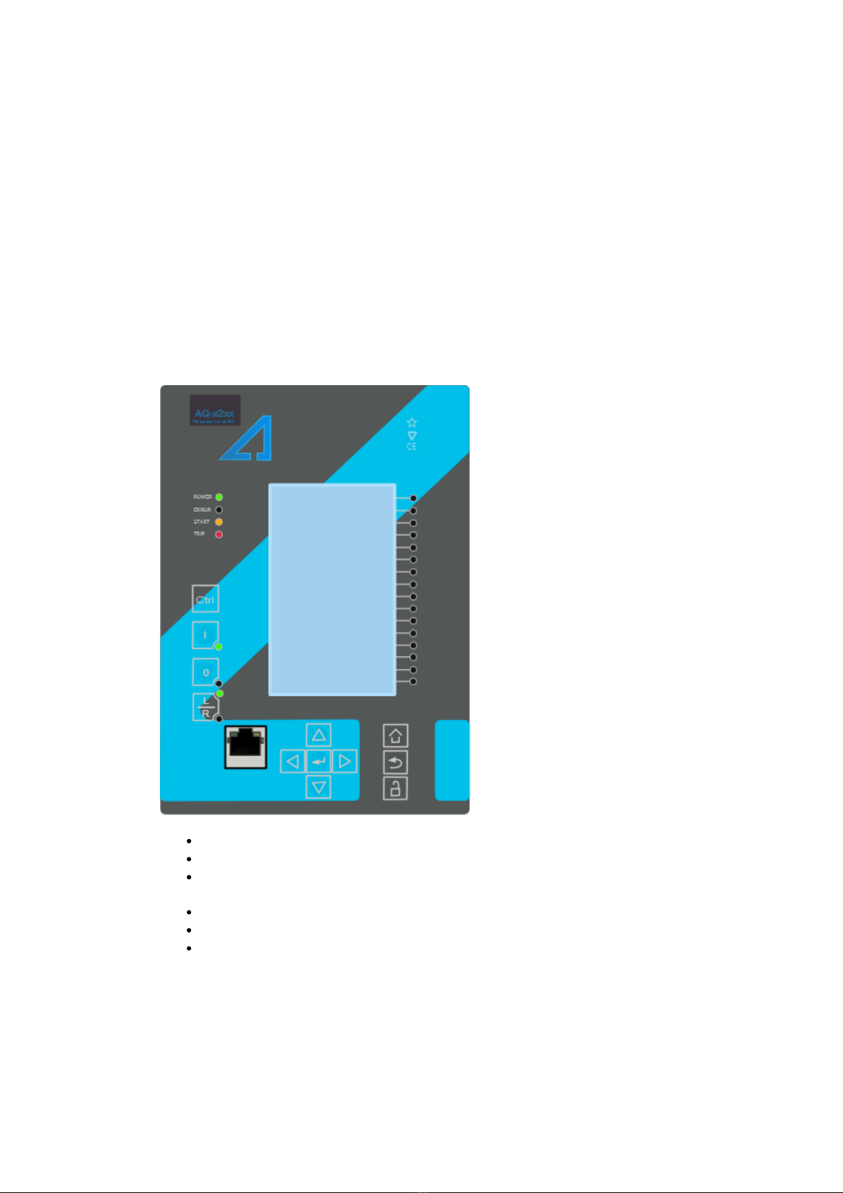
4.1. Panel structure . . . . . . . . . . . . . . . . . . . . . . . . . . . . . . . . . . . . . . . . . . . . . . . . . . . . . . . . . .
4.1.1. AQ 200 series local panel structure . . . . . . . . . . . . . . . . . . . . . . . . . . . . . . . . . . . . .
4.2. Mimic and main menu . . . . . . . . . . . . . . . . . . . . . . . . . . . . . . . . . . . . . . . . . . . . . . . . . . . .
4.2.1. Basic conguration . . . . . . . . . . . . . . . . . . . . . . . . . . . . . . . . . . . . . . . . . . . . . . . . .
4.2.2. Navigation in main conguration menus . . . . . . . . . . . . . . . . . . . . . . . . . . . . . . . . .
4.3. General menu . . . . . . . . . . . . . . . . . . . . . . . . . . . . . . . . . . . . . . . . . . . . . . . . . . . . . . . . . .
4.4. Protection menu . . . . . . . . . . . . . . . . . . . . . . . . . . . . . . . . . . . . . . . . . . . . . . . . . . . . . . . . .
4.5. Control menu . . . . . . . . . . . . . . . . . . . . . . . . . . . . . . . . . . . . . . . . . . . . . . . . . . . . . . . . . . .
4.6. Communication menu . . . . . . . . . . . . . . . . . . . . . . . . . . . . . . . . . . . . . . . . . . . . . . . . . . . .
4.7. Measurement menu . . . . . . . . . . . . . . . . . . . . . . . . . . . . . . . . . . . . . . . . . . . . . . . . . . . . . .
4.8. Monitoring menu . . . . . . . . . . . . . . . . . . . . . . . . . . . . . . . . . . . . . . . . . . . . . . . . . . . . . . . .
4.9. User level password conguration . . . . . . . . . . . . . . . . . . . . . . . . . . . . . . . . . . . . . . . . . . .
5. Functions . . . . . . . . . . . . . . . . . . . . . . . . . . . . . . . . . . . . . . . . . . . . . . . . . . . . . . . . . . . . . . . . .
5.1. Functions included in AQ-F201 . . . . . . . . . . . . . . . . . . . . . . . . . . . . . . . . . . . . . . . . . . . . .
5.2. Measurements . . . . . . . . . . . . . . . . . . . . . . . . . . . . . . . . . . . . . . . . . . . . . . . . . . . . . . . . . .
5.2.1. Current measurement and scaling . . . . . . . . . . . . . . . . . . . . . . . . . . . . . . . . . . . . . .
5.2.2. Frequency tracking and scaling . . . . . . . . . . . . . . . . . . . . . . . . . . . . . . . . . . . . . . . .
5.3. General menu . . . . . . . . . . . . . . . . . . . . . . . . . . . . . . . . . . . . . . . . . . . . . . . . . . . . . . . . . .
5.4. Protection functions . . . . . . . . . . . . . . . . . . . . . . . . . . . . . . . . . . . . . . . . . . . . . . . . . . . . . .
5.4.1. General properties of a protection function . . . . . . . . . . . . . . . . . . . . . . . . . . . . . . .
5.4.2. Non-directional overcurrent I> (50/51) . . . . . . . . . . . . . . . . . . . . . . . . . . . . . . . . . .
5.4.3. Non-directional earth fault I0> (50N/51N) . . . . . . . . . . . . . . . . . . . . . . . . . . . . . . . .
5.4.4. Current unbalance I2> (46) . . . . . . . . . . . . . . . . . . . . . . . . . . . . . . . . . . . . . . . . . . .
5.4.5. Harmonic overcurrent Ih> (50H/51H/68H) . . . . . . . . . . . . . . . . . . . . . . . . . . . . . . .
5.4.6. Circuit breaker failure protection CBFP (50BF) . . . . . . . . . . . . . . . . . . . . . . . . . . . .
5.4.7. Line thermal overload protectionTF> (49F) . . . . . . . . . . . . . . . . . . . . . . . . . . . . .
5.5. Control functions . . . . . . . . . . . . . . . . . . . . . . . . . . . . . . . . . . . . . . . . . . . . . . . . . . . . . . .
5.5.1. Setting group selection (SGS) . . . . . . . . . . . . . . . . . . . . . . . . . . . . . . . . . . . . . . . .
5.5.2. Object control and monitoring (OBJ) . . . . . . . . . . . . . . . . . . . . . . . . . . . . . . . . . . .
5.5.3. Cold load pick-up (CLPU) . . . . . . . . . . . . . . . . . . . . . . . . . . . . . . . . . . . . . . . . . . .
5.5.4. Switch on to fault (SOTF) . . . . . . . . . . . . . . . . . . . . . . . . . . . . . . . . . . . . . . . . . . .
5.5.5. Programmable control switch . . . . . . . . . . . . . . . . . . . . . . . . . . . . . . . . . . . . . . . .
5.6. Monitoring functions . . . . . . . . . . . . . . . . . . . . . . . . . . . . . . . . . . . . . . . . . . . . . . . . . . . .
5.6.1. Current transformer supervision (CTS) . . . . . . . . . . . . . . . . . . . . . . . . . . . . . . . . .
5.6.2. Disturbance recorder (DR) . . . . . . . . . . . . . . . . . . . . . . . . . . . . . . . . . . . . . . . . . .
5.6.3. Measurement recorder . . . . . . . . . . . . . . . . . . . . . . . . . . . . . . . . . . . . . . . . . . . . .
5.6.4. Circuit breaker wear-monitor (CBW) . . . . . . . . . . . . . . . . . . . . . . . . . . . . . . . . . . .
5.6.5. Total harmonic distortion monitor (THD) . . . . . . . . . . . . . . . . . . . . . . . . . . . . . . . .
5.6.6. Measurement value recorder . . . . . . . . . . . . . . . . . . . . . . . . . . . . . . . . . . . . . . . . .
6. System integration . . . . . . . . . . . . . . . . . . . . . . . . . . . . . . . . . . . . . . . . . . . . . . . . . . . . . . . . .
6.1. Communication protocols . . . . . . . . . . . . . . . . . . . . . . . . . . . . . . . . . . . . . . . . . . . . . . . .
6.1.1. NTP . . . . . . . . . . . . . . . . . . . . . . . . . . . . . . . . . . . . . . . . . . . . . . . . . . . . . . . . . . . .
6.1.2. ModbusTCP and ModbusRTU . . . . . . . . . . . . . . . . . . . . . . . . . . . . . . . . . . . . . . . .
6.1.3. ModbusIO . . . . . . . . . . . . . . . . . . . . . . . . . . . . . . . . . . . . . . . . . . . . . . . . . . . . . . .
6.1.4. IEC 103 . . . . . . . . . . . . . . . . . . . . . . . . . . . . . . . . . . . . . . . . . . . . . . . . . . . . . . . . .
6.1.5. DNP3 . . . . . . . . . . . . . . . . . . . . . . . . . . . . . . . . . . . . . . . . . . . . . . . . . . . . . . . . . . .
6.1.6. IEC 101/104 . . . . . . . . . . . . . . . . . . . . . . . . . . . . . . . . . . . . . . . . . . . . . . . . . . . . .
6.1.7. SPA protocol . . . . . . . . . . . . . . . . . . . . . . . . . . . . . . . . . . . . . . . . . . . . . . . . . . . . .
6.2. General IO analog fault registers . . . . . . . . . . . . . . . . . . . . . . . . . . . . . . . . . . . . . . . . . . .
6.3. Real time measurements to communication . . . . . . . . . . . . . . . . . . . . . . . . . . . . . . . . . .
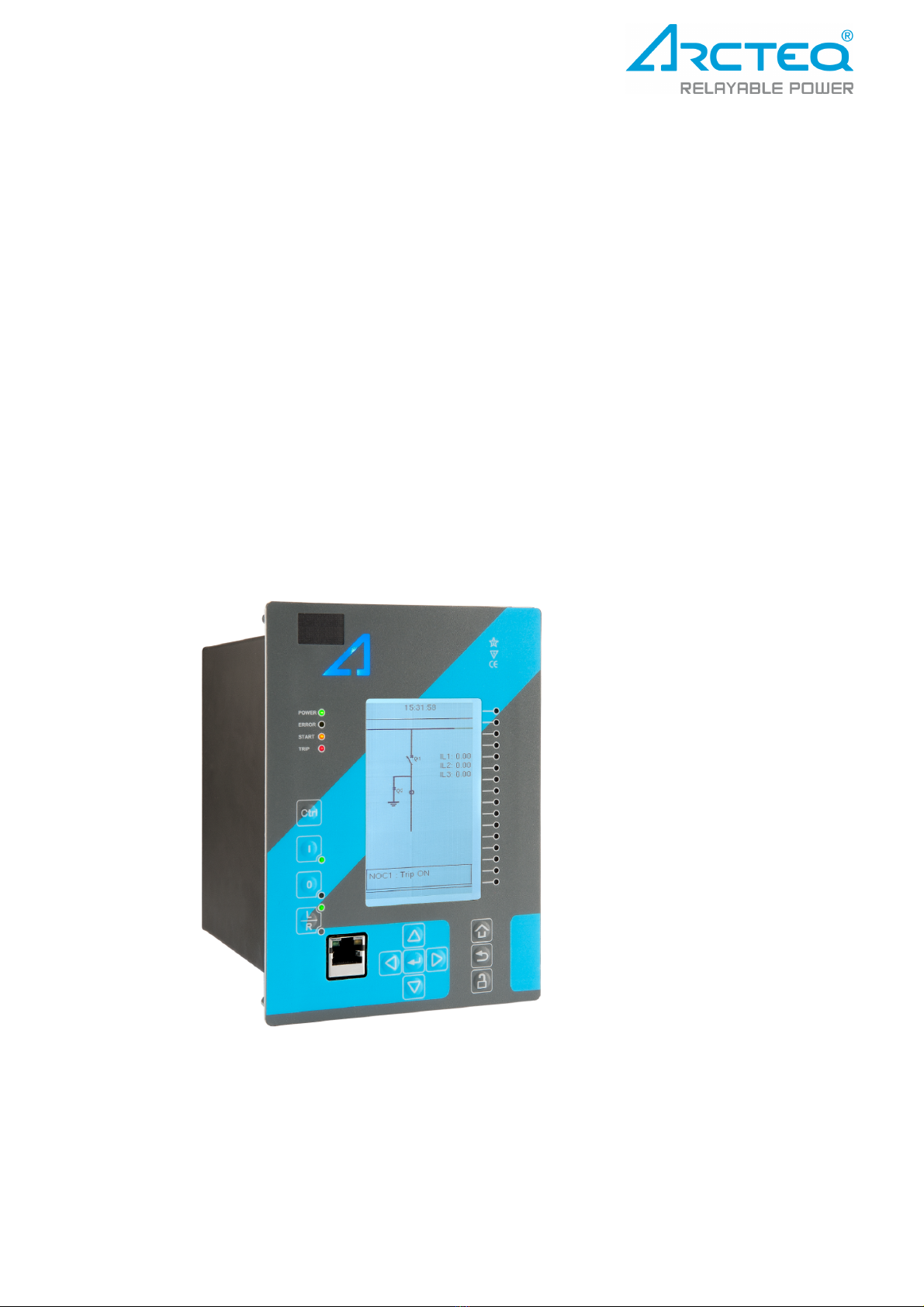
AQ-F201
Instruction manual
Version: 2.00
1 © Arcteq Relays Ltd

182
182
183
184
185
189
189
190
192
192
195
195
195
195
196
196
196
197
198
198
199
199
199
199
200
201
202
203
203
204
204
204
204
205
205
205
206
206
206
207
209
210
7. Applications and connection examples . . . . . . . . . . . . . . . . . . . . . . . . . . . . . . . . . . . . . . . . .
7.1. Connections AQ-F201 . . . . . . . . . . . . . . . . . . . . . . . . . . . . . . . . . . . . . . . . . . . . . . . . . . .
7.2. Example feeder application connection . . . . . . . . . . . . . . . . . . . . . . . . . . . . . . . . . . . . . .
7.3. 3-phase, 3-wire ARON input connection . . . . . . . . . . . . . . . . . . . . . . . . . . . . . . . . . . . . .
7.4. Trip circuit supervision (95) . . . . . . . . . . . . . . . . . . . . . . . . . . . . . . . . . . . . . . . . . . . . . . .
8. Construction and installation . . . . . . . . . . . . . . . . . . . . . . . . . . . . . . . . . . . . . . . . . . . . . . . . .
8.1. Construction and Installation . . . . . . . . . . . . . . . . . . . . . . . . . . . . . . . . . . . . . . . . . . . . . .
8.2. CPU, IO and Power supply module . . . . . . . . . . . . . . . . . . . . . . . . . . . . . . . . . . . . . . . . .
8.3. Current measurement module . . . . . . . . . . . . . . . . . . . . . . . . . . . . . . . . . . . . . . . . . . . . .
8.4. Installation dimensioning . . . . . . . . . . . . . . . . . . . . . . . . . . . . . . . . . . . . . . . . . . . . . . . . .
9. Technical data . . . . . . . . . . . . . . . . . . . . . . . . . . . . . . . . . . . . . . . . . . . . . . . . . . . . . . . . . . . . .
9.1. Hardware . . . . . . . . . . . . . . . . . . . . . . . . . . . . . . . . . . . . . . . . . . . . . . . . . . . . . . . . . . . . .
9.1.1. Measurements . . . . . . . . . . . . . . . . . . . . . . . . . . . . . . . . . . . . . . . . . . . . . . . . . . . .
9.1.1.1. Current measurement . . . . . . . . . . . . . . . . . . . . . . . . . . . . . . . . . . . . . . .
9.1.1.2. Frequency measurement . . . . . . . . . . . . . . . . . . . . . . . . . . . . . . . . . . . . .
9.1.2. CPU & Power supply . . . . . . . . . . . . . . . . . . . . . . . . . . . . . . . . . . . . . . . . . . . . . . .
9.1.2.1. Auxiliary voltage . . . . . . . . . . . . . . . . . . . . . . . . . . . . . . . . . . . . . . . . . . . .
9.1.2.2. CPU communication ports . . . . . . . . . . . . . . . . . . . . . . . . . . . . . . . . . . . .
9.1.2.3. CPU Binary inputs . . . . . . . . . . . . . . . . . . . . . . . . . . . . . . . . . . . . . . . . . .
9.1.2.4. CPU Binary outputs . . . . . . . . . . . . . . . . . . . . . . . . . . . . . . . . . . . . . . . . .
9.1.3. Display . . . . . . . . . . . . . . . . . . . . . . . . . . . . . . . . . . . . . . . . . . . . . . . . . . . . . . . . . .
9.2. Functions . . . . . . . . . . . . . . . . . . . . . . . . . . . . . . . . . . . . . . . . . . . . . . . . . . . . . . . . . . . . .
9.2.1. Protection functions . . . . . . . . . . . . . . . . . . . . . . . . . . . . . . . . . . . . . . . . . . . . . . . .
9.2.1.1. Non-directional overcurrent (50/51) I> . . . . . . . . . . . . . . . . . . . . . . . . . . .
9.2.1.2. Non-directional earth fault (50N/51N) I0> . . . . . . . . . . . . . . . . . . . . . . . .
9.2.1.3. Current unbalance (46/46R/46L) I2> . . . . . . . . . . . . . . . . . . . . . . . . . . . .
9.2.1.4. Harmonic overcurrent (50H/51H, 68) Ih> . . . . . . . . . . . . . . . . . . . . . . . .
9.2.1.5. Circuit breaker failure protection (50BF/52BF) CBFP . . . . . . . . . . . . . . .
9.2.1.6. Line thermal overload(49L) TF> . . . . . . . . . . . . . . . . . . . . . . . . . . . . . . .
9.2.2. Control functions . . . . . . . . . . . . . . . . . . . . . . . . . . . . . . . . . . . . . . . . . . . . . . . . . .
9.2.2.1. Setting group selection . . . . . . . . . . . . . . . . . . . . . . . . . . . . . . . . . . . . . .
9.2.2.2. Object control (OBJ) . . . . . . . . . . . . . . . . . . . . . . . . . . . . . . . . . . . . . . . .
9.2.2.3. Cold load pick-up (CLP) . . . . . . . . . . . . . . . . . . . . . . . . . . . . . . . . . . . . . .
9.2.2.4. Switch on to fault (SOTF) . . . . . . . . . . . . . . . . . . . . . . . . . . . . . . . . . . . . .
9.2.3. Monitoring functions . . . . . . . . . . . . . . . . . . . . . . . . . . . . . . . . . . . . . . . . . . . . . . .
9.2.3.1. Current transformer supervision (CTS) . . . . . . . . . . . . . . . . . . . . . . . . . .
9.2.3.2. Disturbance recorder (DR) . . . . . . . . . . . . . . . . . . . . . . . . . . . . . . . . . . . .
9.2.3.3. Circuit breaker wear monitor (CBW) . . . . . . . . . . . . . . . . . . . . . . . . . . . .
9.2.3.4. Total harmonic distortion (THD) . . . . . . . . . . . . . . . . . . . . . . . . . . . . . . . .
9.3. Tests and environmental . . . . . . . . . . . . . . . . . . . . . . . . . . . . . . . . . . . . . . . . . . . . . . . . .
10. Ordering information . . . . . . . . . . . . . . . . . . . . . . . . . . . . . . . . . . . . . . . . . . . . . . . . . . . . . . .
11. Contact and reference information . . . . . . . . . . . . . . . . . . . . . . . . . . . . . . . . . . . . . . . . . . . .
AQ-F201
Instruction manual
Version: 2.00
© Arcteq Relays Ltd 2

Disclaimer
Please read these instructions carefully before using the equipment or taking any other actions with
respect to the equipment. Only trained and qualied persons are allowed to perform installation,
operation, service or maintenance of the equipment. Such qualied persons have the responsibility to
take all appropriate measures, including e.g. use of authentication, encryption, anti-virus programs,
safe switching programs etc. necessary to ensure a safe and secure environment and usability of the
equipment. The warranty granted to the equipment remains in force only provided that the instructions
contained in this document have been strictly complied with.
Nothing contained in this document shall increase the liability or extend the warranty obligations of the
manufacturer Arcteq Relays Ltd. The manufacturer expressly disclaims any and all liability for any
damages and/or losses caused due to a failure to comply with the instructions contained herein or
caused by persons who do not full the aforementioned requirements. Furthermore, the manufacturer
shall not be liable for possible errors in this document.
Please note that you must always comply with applicable local legislation and regulations. The
manufacturer gives no warranties that the content of this document is in all respects in line with local
laws and regulations and assumes no liability for such possible deviations.
You are advised to notify the manufacturer in case you become aware of any errors in this document or
of defects in the equipment.
The manufacturer reserves the right to update or amend this document at any time.
AQ-F201
Instruction manual
Version: 2.00
3 © Arcteq Relays Ltd

Copyright
Copyright © Arcteq Relays Ltd. 2018. All rights reserved.
AQ-F201
Instruction manual
Version: 2.00
© Arcteq Relays Ltd 4

1. Manual revision notes
1.1. Version 2 revision notes
Revision 2.00
Date 6.6.2019
Changes
- New more consistent look.
- Improved descriptions generally in many chapters.
- Improved readability of a lot of drawings and images.
- Updated protections included included in every IED manual.
- Every protection IED type now has connection drawing, application example drawingwith function block diagram
and application example with wiring.
- Added General-menu description.
1.2. Version 1 revision notes
Revision 1.00
Date 8.1.2013
Changes - The rst revision for AQ-F201
Revision 1.01
Date 22.11.2013
Changes
- Order code update, technical data update
- Measurements chapter added
- IED user interface chapter added
Revision 1.02
Date 19.1.2015
Changes - Updated technical data
- Added System integration texts: NTP, Modbus TCP/RTU, ModbusIO, IEC103 and SPA
Revision 1.03
Date 12.6.2015
Changes - Updated technical data
- Added System integration texts: NTP, Modbus TCP/RTU, ModbusIO, IEC103 and SPA
Revision 1.04
Date 12.1.2016
Changes - Added digital input operation description
- Improved formatting
Revision 1.05
Date 30.5.2016
Changes - Added PCB and Terminal options to order code.
Revision 1.06
Date 30.8.2016
Changes - Added password set up guide (previously only in AQtivate user guide)
Revision 1.07
Date 16.1.2016
Changes - Order code updated
AQ-F201
Instruction manual
Version: 2.00
5 © Arcteq Relays Ltd

Revision 1.08
Date 12.12.2017
Changes
- Measurement value recorder description
- ZCT connection added to current measurement description
- Ring-lug CT card option description added
- Order code revised
- Non-standard inverse time delay curves added
- Internal harmonic blocking parameter to I>,I0> functions
Revision 1.09
Date 13.4.2018
Changes - I> and I0> pick-up ranges updated.
Revision 1.10
Date 9.8.2018
Changes - THD monitoring description added.
- Line thermal overload protection description added.
Revision 1.11
Date 18.1.2019
Changes - HMI display technical data added
AQ-F201
Instruction manual
Version: 2.00
© Arcteq Relays Ltd 6

2. Abbreviations
CB – Circuit breaker
CBFP – Circuit breaker failure protection
CT – Current transformer
CPU – Central processing unit
EMC – Electromagnetic compatibility
HMI – Human machine interface
HW – Hardware
IED – Intelligent electronic device
IO – Input output
LED – Light emitting diode
LV – Low voltage
MV – Medium voltage
NC – Normally closed
NO – Normally open
RMS – Root mean square
SF – System failure
TMS – Time multiplier setting
TRMS – True root mean square
VAC – Voltage alternating current
VDC – Voltage direct current
SW – Software
uP - Microprocessor
AQ-F201
Instruction manual
Version: 2.00
7 © Arcteq Relays Ltd

3. General
AQ-F201 Overcurrent and Earth-fault relay is a member of the AQ-200 product line. The AQ-200
protection product line in respect of hardware and software is a modular concept and even if the AQ-
F201 is member of the product line it does not support the user customizable modularity either in
software or hardware. Instead AQ-F201 is provided as xed Overcurrent and Earth-fault relay with
factory set IO and functionality. This manual describes the specic application of the AQ-F201
Overcurrent and Earth-fault relay only. For other AQ-200 series products please consult corresponding
device manuals.
AQ-F201
Instruction manual
Version: 2.00
© Arcteq Relays Ltd 8

4. IED user interface
4.1. Panel structure
AQ 200 series IED user interface section is divided into hardware- and software user interface
sections. Software interface is divided into local panel conguration and programming by using
AQtivate 200 freeware software suite.
4.1.1. AQ 200 series local panel structure
AQ 200 series IED have multiple LEDs, control buttons and local RJ-45 Ethernet port for conguration
on front as a default. On rear each unit is equipped with RS-485 serial interface and RJ-45 Ethernet
interface options as a standard. See list below.
Figure. 4.1.1. - 1. Local panel structure.
4 default LEDs: Power, Error, Start (congurable) and Trip (congurable).
16 freely congurable LEDs with programmable legend texts.
3 object control buttons: Choose the controllable object with Ctrl –button, control breaker with
0- and I push buttons.
L/R push button for switching between local and remote control modes.
7 Navigation buttons for IED local programming and a button for password activation.
RJ-45 Ethernet port for IED conguration.
Power LED is lit (green) when unit is powered on. Error LED is lit (red) when relay has an internal error
that affects the operation of the unit. This can be either a hardware or software error. Start LED
(yellow) and Trip LED (red) activation is user settable. Activation and color (green/yellow) of the 16
LEDs on the right side of the display are user settable.
AQ-F201
Instruction manual
Version: 2.00
9 © Arcteq Relays Ltd

4.2. Mimic and main menu
4.2.1. Basic conguration
IED user interface is divided into 5 quick displays. The displays are Events, Favorites, Mimic, LEDs and
Clock. Default quick display is the mimic view and it is possible to glance through these menus by
pressing arrows left and right. Please note that the available quick display carousel views might be
different if user has changed it with AQtivate setting tools Carousel Designer. Home button transfers
the user between quick display carousel and main conguration menus. Main conguration menus are
General, Protection, Control, Communication, Measurements and Monitoring. Available menus vary
depending on IED type. You can choose the main menu by using the four arrow keys and press enter.
Figure. 4.2.1. - 2. Basic navigation.
Cancel/Back keytakes you one step back or holding it down for 3 seconds takes you back to
general –menu.Cancel key is also used for resettinguser alarm LEDs.
Padlock buttontakes user to password menu where it is possible to enter different user levels
(user, operator, congurator and super user).
4.2.2. Navigation in main conguration menus
All the settings in this IED type have been divided into main conguration menus. Main conguration
menus are presented below. Available menus may vary according to IED type.
Figure. 4.2.2. - 3. Main conguration menus.
AQ-F201
Instruction manual
Version: 2.00
© Arcteq Relays Ltd 10

4.3. General menu
Device info
Figure. 4.3. - 4. Device Info sub- menu.
Set name and location of the device.
Serial number and SW version of the IED.
Hardware conguration (order code).
Source for time synchronization, Internal or External (internal as default).
Enable stage forcing (disabled / enabled). When forcing is disabled after using every forced
output will restore. Forcing is done individually in info menu of each stage.
Language selection, all available languages here (English as default).
Clear devices events.
LCD contrast level and setting 0…255 (120 as default).
Reset latched signals
Protection/Control/Monitor prole: Displays the status of enabled functions.
4.4. Protection menu
Protection menuincludes Stage activation sub-menu and sub-menus for different protection functions
like Overcurrent, Earthfault, Seq. and balance and Supporting. Valid protection functions vary
according IED type.
AQ-F201
Instruction manual
Version: 2.00
11 © Arcteq Relays Ltd

Figure. 4.4. - 5. Protection menu view. Protection stages vary according IED type.
STAGE ACTIVATION
Figure. 4.4. - 6. Stage activation sub-menu.
Activation of different protection stages is done in Stage activation –sub menu. Each protection
stage and supporting function is disabled as standard.
Activated menus will appear below the stage specic sub-menu for example I> appears below
Current –module, U< appears below Voltage-module etc.
EXAMPLE PROTECTION STAGE
AQ-F201
Instruction manual
Version: 2.00
© Arcteq Relays Ltd 12

Figure. 4.4. - 7. Stage navigation and modication.
Each protection stage and supportive function has ve stage menus Info, Settings, Registers, IO and
Events.
AQ-F201
Instruction manual
Version: 2.00
13 © Arcteq Relays Ltd

Figure. 4.4. - 8. Info menu indicates all the details listed below certain protection stage or function.
Function is activated and disabled in Stage activation menu. It is possible to disable function in
Info menu as well.
Function condition indicates whether the stages condition is Normal, Start or Trip.
Measured amplitude can be Peak-to-peak, TRMS or RMS. As a default it is set as RMS.
Under Characteristic graphs-title you can open graphs related to the protection function.
Info view has calculator for function starts, trips and blockings. It is possible to clear calculators
by choosing Clear statistics and Clear.
Measurements are visible in Info menu.
Active setting group and its settings are all visible in Info menu.
AQ-F201
Instruction manual
Version: 2.00
© Arcteq Relays Ltd 14

Figure. 4.4. - 9. All group specic settings are done individually in Settings menu.
Stage settings vary according different protection functions. With factory settings only one group of
eight is activated. To enable more groups go to Control menu and select Setting Groups.
Figure. 4.4. - 10. Stage information is divided into two sections.
AQ-F201
Instruction manual
Version: 2.00
15 © Arcteq Relays Ltd

Specic fault data of IEDs is stored in operation log under the register. Each of these 12 logs includes
pre-fault current, fault current, time stamp and active group during the triggering. Operation log can be
cleared by choosing
Clear registers
→
Clear
.
Events generated by the specic stage can be checked by going to Stage event register. General
events cannot be cleared.
Figure. 4.4. - 11. Stage information is divided into two sections.
Starting and tripping signals of protection stages are connected to physical outputs in Direct Output
Control menu. It is possible to connect to output relay or to start- trip- or user congurable LED. In
case when stage is internally blocked (DI or other signal) it is possible to congure an output to indicate
that stage is blocked. Connection to outputs can be either latched |x| or non-latched x.
Stage blocking is done in Blocking Input Control menu. Blocking can be done by using digital inputs,
logical inputs or outputs, stage start- trip- or blocked information or by using object status information.
AQ-F201
Instruction manual
Version: 2.00
© Arcteq Relays Ltd 16

Figure. 4.4. - 12. Protection stage related events are masked on and off individually under
Events
→
Event mask
.
Events are masked off as default. It is possible to activate desired events by masking them |x|. Only
masked events appear to event list. Events cannot be cleared.
Stage activation
Figure. 4.4. - 13. Stage activation sub-menu.
Activation
of different protection stages is done in
Stage activation
–sub menu. Each protection
stage and supporting function is disabled as standard.
Activated menus will appear below the stage specic sub-menu for example I> appears below
Current –module, U< appears below Voltage-module etc.
AQ-F201
Instruction manual
Version: 2.00
17 © Arcteq Relays Ltd

Example protection stage
Figure. 4.4. - 14. Stage navigation and modication.
Each protection stage and supportive function has ve stage menus
Info, Settings, Registers, IO
and
Events.
AQ-F201
Instruction manual
Version: 2.00
© Arcteq Relays Ltd 18

Info-menu
Figure. 4.4. - 15. Info menu indicates all the details listed below certain protection stage or function.
Function is activated and disabled in
Stage activation
menu. It is possible to disable function in
Info menu as well.
Function condition
indicates whether the stages condition is Normal, Start or Trip.
Measured amplitude
can be Peak-to-peak, TRMS or RMS. As a default it is set as RMS.
Available measured amplitudes vary.
Under
Characteristic graphs
-title you can open graphs related to the protection function.
Info view has calculator for function starts, trips and blockings. It is possible to clear calculators
by choosing Clear statistics and Clear.
Measurements
are visible in Info menu.
Active setting group
and its settings are all visible in Info menu. Other setting groups can be set
in the
Settings
-menu.
AQ-F201
Instruction manual
Version: 2.00
19 © Arcteq Relays Ltd
Other manuals for AQ-F201
3
Table of contents
Other Arcteq Relay manuals

Arcteq
Arcteq AQ-F201 User manual

Arcteq
Arcteq AQ-F210 User manual

Arcteq
Arcteq AQ-S215 User manual

Arcteq
Arcteq AQ-S254 User manual

Arcteq
Arcteq AQ-T257 User manual

Arcteq
Arcteq AQ F205 User manual

Arcteq
Arcteq AQ F205 User manual

Arcteq
Arcteq AQ 1000 User manual

Arcteq
Arcteq AQ-F255 User manual

Arcteq
Arcteq AQ-R215 User manual
Popular Relay manuals by other brands

CD Automation
CD Automation REVO S IFH 1PH user manual

Siemens
Siemens SIRIUS 3TK2821 operating instructions

Rockwell Automation
Rockwell Automation Allen-Bradley Guardmaster 440R-GL2S2P user manual

CRE Technology
CRE Technology SCR2.0 user manual

HDL
HDL HDL-MPR02-RF.18 user manual

Areva
Areva MCAG 19 Service manual