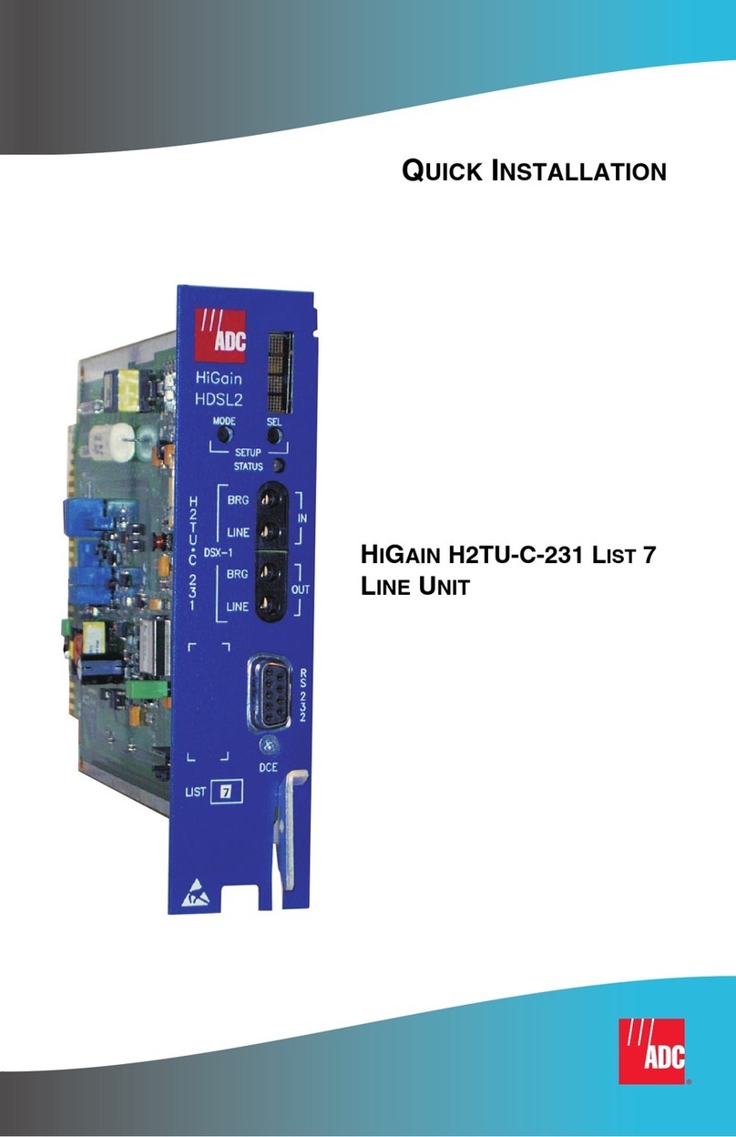
SEA 9711 User manual

Hardware Manual - Operation Instructions and Safety Guidelines
SEA 9711 WLA Module
Order No.: 60000009
Doc. No.: HB/SEA 9711 Hardware Manual/2.0.8/Jan/ 16

Content
Getting Started.....................................................................4
Safety Guidelines ................................................................6
Restrictions for Hazardous Locations ............................................7
Restrictions for Hazardous Voltages..............................................7
Operator Protection......................................................................7
Setup & Operation...............................................................9
Prerequisites................................................................................9
Connectors...................................................................................9
Indicators....................................................................................10
Installing the SEA 9711 Module on the Chassis.............................11
Wiring the SEA 9711 Module........................................................12
Installing and Operating Antenna................................................13
Sleep Mode.................................................................................14
Specifications.....................................................................15
WLA Characteristics...................................................................15
Power Requirements....................................................................15
Physical Characteristics...............................................................17
Environmental Conditions............................................................18
Shock and Vibration....................................................................18
CE Compliance (EMC, R&TTE)........................................................19
FCC Compliance...........................................................................19
Japan Radio Compliance..............................................................20
2 Operation Instructions

Maintenance.......................................................................21
Contact Information ...........................................................22
Operation Instructions 3

Getting Started
Be ore starting to work with the SEA 9711 WLAN module please read the
ollowing in ormation and the complete so tware manual and care ully.
We believe that all in ormation in this manual is accurate. The document
has been care ully reviewed or technical accuracy. In the event o tech-
nical or typographical errors, we reserve the right to make changes to
subsequent editions o this document without prior notice to holders o
this edition.
The reader should consult the vendor i errors are suspected.
Be ore using or operating any SEA 9711 module and the provided
so tware you have to agree to the terms and conditions. I you do
NOT agree you can resend the hardware and so tware package
within a period o two weeks a ter delivery. In this case S.E.A. will
re und the product price and shipping costs.
I there are any questions about operating the module or i any
term in this manual is not understood, please contact S.E.A. Dat-
entechnik GmbH be ore using the module.
The terms and conditions are listed in the so tware manual which
is provided on the Installation CD ROM. Please read the manual
chapters: Disclaimer, Limitation of Liability, and User Responsib-
ilities be ore using the device.
4 Operation Instructions

For in ormation about National Instruments™ hardware please
re er to the appropriate National Instruments™ manual.
For in ormation about con iguration or programming o the SEA
9711 module, please re er to the so tware manual.
Operation Instructions 5

Safety Guidelines
Operate the SEA 9711 module only as described in this operation instruc-
tions and the module so tware manual. Please check the S.E.A. website
or updates o this manual or technical speci ications.
Hot or Cold
Surface
Operated in hot or cold environments less than 10
°C or higher than 30 °C the metallic sur ace o the
module might become hot or cold as well.
Touching the sur ace may result in bodily injury.
Do not dismount the module rom the chassis dur-
ing operation. Wait until the module temperature
has reached 20 °C.
Do not disconnect connectors unless power has been switched
completely o and the area is known to be non hazardous.
Do not remove modules unless power has been switched com-
pletely o or the area is known to be non hazardous.
Guarantee void i seal is broken!
Do not open or disassemble the module or other hardware parts.
6 Operation Instructions

Restrictions for Hazardous Locations
The SEA 9711 modules are suitable or use in non hazardous locations
only. Please note:
Do not use or medical applications.
Do not use in sa ety critical applications.
Keep the system away rom hazardous locations, explosive or
high voltage areas.
Protect the system rom thunderstorm and lightning strikes or
other electrical hazards.
Restrictions for Hazardous Voltages
Hazardous voltages must not
be connected to the SEA 9711 module. A
hazardous voltage is a voltage higher than 33 Vpeak AC or DC to earth
ground. Never connect AC voltages to the module.
Operator Protection
To protect persons against any harm, the ollowing rules have to be ol-
lowed:
Operation Instructions 7

Use any part or the complete system only in dry areas. Do not op-
erate the module in bath areas, kitchens etc., where water or va-
pour can be in contact with the module, cables, or antennas.
Use only isolated power supplies with a nominal voltage o 12 V,
which are made or use with CompactRIO™ or CompactDAQ™
systems.
It is not allowed to use the system or any kind o medical applic-
ations or apparatus.
The module must not be operated in explosive areas.
8 Operation Instructions

Setup & Operation
Prerequisites
The SEA 9711 module can be operated with a National Instruments™
CompactRIO™ or CompactDAQ™ system. The ollowing additional hard-
ware is required (not part o module shipment, but mandatory or opera-
tion):
Power cable (order no. 61000011)
WLAN router or PC/Laptop with WLAN card
WLAN antenna
Connectors
The back side connector (SUB-D 15) is designated to operate the SEA
9711 module within any National Instruments™ CompactRIO™ or Com-
pactDAQ™ chassis. Other devices must not be connected to this con-
nector. I the SEA 9711 module is operated stand-alone this connector is
not used.
The ront side provides all connectors required or operation, re er to Fig.
1: Front Side:
external power supply connector (2) to eed the module with ex-
ternal power (e.g. rom the CompactRIO™ controller)
Operation Instructions 9

WLAN antenna connector (3) to connect an external WLAN an-
tenna
RJ45 twisted pair connectors to connect any
Ethernet based devices to the Compact-
RIO™ controller (4) + (5).
Special purpose RJ45 twisted pair connect-
or to connect CompactRIO™ controller (6).
The Ethernet ports (4) + (5) are
not accessible by WLAN.
Indicators
The LEDs (1) on the ront side o the module indic-
ate the current status and di erent unctions ( rom
le t to right):
LED # SEA 9711 Module
1 Backplane Power 5 V
2 External Power
3 LAN -> WLAN Activity
4 WLAN-RF- Activity
10 Operation Instructions
Fig. 1: Front Side

Installing the SEA 9711 Module on the Chassis
Be ore inserting the SEA 9711 module in the CompactRIO™ chassis,
please disconnect any connectors to the CompactRIO™ system and
switch-o the power supply. Make sure that you are working in an ESD
sa e environment.
Operation Instructions 11
1
WLAN
antenna
3
2
Controller
bridge

The module may be installed in any ree CompactRIO™ or Compact-
DAQ™ slot. The provided customized Ethernet cable is suitable or usage
o the module in slot 1.
Wiring the SEA 9711 Module
To connect the peripheral components to the ront side o the SEA 9711
module and ollow the steps described below:
1. WLA antenna
Connect the WLAN antenna to the WLAN socket connector.
2. Power Connector
Connect the power cables delivered with
the module to the main controllers
power supply and plug the connector
into the power socket o the module.
Make sure that the CompactRIO™
power supply is switched o be ore
making any external connections. The
input voltage range o the external power connector is 7 V to 30
V DC. Check the polarity o the wires be ore powering the sys-
tem – see Fig. 2. The module comes with a reverse voltage pro-
tection. Connect and disconnect any power cabling when
power is generally switched o .
3. Bridge
12 Operation Instructions
Fig. 2: xternal Power

Connect the Ethernet bridge port (bottom) o the module with
the CompactRIO™ Controller by a patch cable.
Installing and Operating Antenna
The word transmitter is used interchangeably with the wording SEA 9711
module, and means the RF-transmitter or RF-receiver part o the module.
The antenna has to be properly mounted at the desired location.
I a roo antenna is used, the antenna has to be dismounted when light-
ning strike is expected. The SEA 9711 module and any antenna or cabling
is not protected against lightning strike or any over-voltage. Do not oper-
ate the transmitter or antenna during thunderstorms, and keep the an-
tenna away rom any kind o elevation. Keep the system away rom haz-
ardous locations, explosive or high voltage areas.
Protect the system rom lightning strikes.
To minimize the radio requency exposure to humans, the ollowing rules
have to be attended:
Operating the transmitter, cabling, and antennas it is mandatory
to keep a distance o at least 1 m /3,3 t to persons.
Use only antenna types, which are oreseen or the use with the
transmitter. I unsure ask the module supplier.
Operation Instructions 13

Do not operate the SEA 9711 module and antenna near other RF
systems.
Use only antenna cables and connectors, which are made or
WLAN systems and requencies. Do not bend the antenna cabling
less than the bending radius o 30 mm.
Do not open or disassemble the SEA 9711 module, antenna, or
other supplied hardware components. There are no components
inside which need to be serviced.
Sleep Mode
The sleep mode can be enabled or the
complete CompactRIO™ system by
so tware. In sleep mode typically there
is no communication with the module.
Power consumption is minimized. The
system thermal dissipation may de-
crease. The SEA 9711 must be inserted
in a chassis to use this eature.
The module enables sleep
mode by de ault, i the module
should not all into sleep
mode, switch to disable.
14 Operation Instructions
Fig. 3: nable/Disable Sleep Mode

Specifications
The ollowing speci ications are typical or the range o -40 to 60 °C un-
less otherwise noted.
The SEA 9711 module is powered by the CompactRIO™ backplane con-
nector (5 V) and additionally by an external power connector (see ollow-
ing speci ications) on the ront panel (Front Connector).
WLA Characteristics
Network mode Bridging
Frequency range [GHz] 2.412-2.484
Operating distance [m] 100
WLAN Standard [54Mbit/s] 802.11 b/g
Switch # o ports* 2 (3)
Power Requirements
Operating voltage or the external ront panel power supply
Nominal 12 V DC
Minimal 7 V DC
* I the module is connected to an external CompactRIO™ or similar system, one Ethernet port is used.
Operation Instructions 15

Maximal 30 V DC
Over voltage protection maximum 33 V
Average operating current:
Front Connector
Current at 12V nominal in [Arms]
Backplane
Current [A]
min. typ. max. typ. sleep
0.275 0.290*0.335 0.006 0.006
* with maximum bandwidth (rms It=8ms)
16 Operation Instructions

Physical Characteristics
Weight 205 g
Size 74 x 23 x 87 mm
Operation Instructions 17
Typical ront connector current during active WLAN transmission (Power supply = 12VDC)

Environmental Conditions
SEA 9711 modules are intended or indoor use only. For outdoor use,
mount the complete system in a suitable rated enclosure. Re er to the in-
stallation instructions or the chassis or more in ormation about how to
meet these speci ications.
Operating temperature - 40 to 60 °C
Storage temperature - 40 to 80 °C
Ingress protection IP 30 (with connected power
cable)
Operating humidity 5 % - 90 % relative humidity,
non condensing
Maximum altitude 2000 m
Shock and Vibration
To meet these speci ications, the CompactRIO™ or CompactDAQ™ sys-
tem has to be panel mounted and the antenna connectors have to be
screwed.
Operating vibration:
random IEC 60068-2-64 5 grms, 10 to 575 Hz
sinusoidal IEC 60068-2-6 5 g, 10 to 575 Hz
18 Operation Instructions

Operating shock:
IEC 60068-2-27 15 g, 11 ms hal sine,
30 g, 11 ms hal sine,
50 g, 3 ms hal sine,
10 shocks at 6 orientations
CE Compliance (EMC, R&TTE)
In order to satis y the essential requisite o the R&TTE 99/5/EC directive,
the SEA 9711 modules are compliant with the ollowing standards:
EMC directive (Electromagnetic Compatibility). 89/336/EEC EMC;
standards: EN 301 489-1 and EN 301 489-7
Directive (R&TTE) 1999/5/EC
This product meets the essential requirements o applicable
European Directives.
FCC Compliance
This SEA 9711 module complies with part 15 o the FCC rules
and contains RF-device according to FCC ID: R68WIPORT IC:
3867AWIPORT
Operation Instructions 19

Japan Radio Compliance
The Japan Radio Certi ication Number is: 004NYDA0091
For EMC compliance, it is recommended to operate the SEA 9711 modules
with original and shielded antenna cabling only.
For urther in ormation please re er to: www.sea-gmbh.com
To meet the RF exposure rules and regulations:
The antenna(s) used or this transmitter have to be installed to
provide a separation distance o at least 1 m/3,3 t rom persons
and must not be co-located or operated in conjunction with any
other antenna or transmitter.
The antenna(s) used or this module must not exceed 7 dBi or
mobile and ixed or mobile operating con igurations.
Users and installers have to ollow the transmitter operating and
antenna installation instructions. To satis ying RF exposure com-
pliance, please re er to the user manual o the antenna setup.
20 Operation Instructions
Table of contents
