manuals.online logo
Brands
  1. Home
  2. •
  3. Brands
  4. •
  5. Symantec
  6. •
  7. Network Hardware
  8. •
  9. Symantec SSL Visibility SV800 User manual

Symantec SSL Visibility SV800 User manual

Page 1
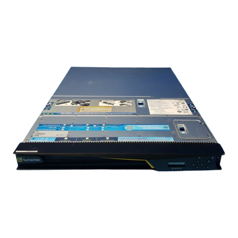
This Quick Start Guide documents the SV800, SV1800/1800B, SV2800/2800B, and
SV3800/3800B/3800B-20 appliances. Instructions for the SV1800, SV2800, and SV3800
apply also to the ‘B’ versions of those appliances. For more information, refer to the
appliance’s Getting Started Guide.
01 Unpack the Appliance
Verify the contents of the shipping package for the SSL Visibility appliance:
SV800 SV1800 SV2800 SV3800
External power supply with AC power cord
√
Two AC power cords
√√√
Rack-mount rail kit √√√
Rack-mount ears with fasteners √√√
Safety and Regulatory Compliance Guide
√√√√
Quick Start Guide (this document) √√√√
Software License Agreement √√√√
Hardware Warranty √√√√
02 Install the Netmods — SV2800 & SV3800 Only
The SV2800 and SV3800 appliances do not include Network Modules (Netmods), which must
be purchased separately from Symantec. The Netmods are installed in the front bays of the
appliance with the ports numbered left to right and top to bottom.
Note: The SV800 and SV1800 appliances include integrated Ethernet ports.
Warning: Netmods are not hot-swappable. Make sure to power off the appliance before
installing or removing them. Failing to do so could damage the Netmods.
To install a Netmod:
a. Power off the appliance.
b. Remove the Netmod carrier:
oRemove the screw from the lever of the Netmod carrier, pulling the lever away from the
Netmod carrier, approximately 1” (25mm), so the latch releases.
oGently pull the Netmod carrier out of the slot.
c. Insert the Netmod:
oInsert the Netmod in the empty slot, making sure the far end of the latch is inside the
slot and the near end of the latch touches the outside of the slot.
oPress gently on the Netmod lever, where the screw hole is, while pushing the module into
the chassis, so the latch engages.
oMake sure the Netmod aligns with the other modules. It may be necessary to push on
the front of the module to fully seat it. If the module does not fully seat, try reinserting it
while observing the lever’s latch on the right side of the module.
oSecure the lever to the front of the chassis with the previously removed screw.
03 Connect Cables
Symantec recommends plugging in cables, verifying LEDs, and configuring and licensing
the appliance before rack-mounting it. If you would rather rack-mount the appliance before
performing configuration tasks, skip to Step 8—Rack-Mount the Appliance.
Note: Network cables are not included with the appliance. Make sure to use only straight-
through Ethernet cables. For 1000Base-T operation, Symantec recommends Category 5E cables
or better (Category 6 or 6A) for distances of 330 feet (100 meters).
To connect the appliance’s cables:
a. Connect the appliance to a management workstation with a browser:
oFor SV800 appliances, connect the front-panel Management Ethernet port to a
management workstation, either directly or through a management network. Use an
appropriate Ethernet cable.
oFor the SV1800, SV2800, and SV3800, connect the rear-panel Management Ethernet1
port to a management workstation, either directly or through a management network.
Use an appropriate Ethernet cable.
Warning: When deploying the SV1800, SV2800, and SV3800 appliances, do not connect
to the Management Ethernet 2 port. This port is not functional.
b. For terminal connections to the appliance, connect the appliance’s rear-panel serial port to
a serial terminal or to a workstation with terminal emulation software.
c. Connect the included power cords to the appliance:
oFor SV800 appliances, connect the external power adapter plug to the appliance’s DC
power inlet on the rear panel.
oFor SV1800, SV2800, and SV3800 appliances, connect the two AC power cords to the
appliance’s AC power inlets on the rear panel. Two power supplies are provided for
redundant operation.
d. Connect the other ends of the power cords to a 120V or 220V power source.
Warning: Always wait at least 5 seconds between disconnecting and reconnecting power cables.
Note: For deployment information, refer to the appliance’s Getting Started Guide.
04 Power on the Appliance and Verify LEDs
To verify the appliance is operational:
a. Confirm the appliance’s power cord or power cords are securely connected to a 120V or
220V power source.
b. Power on the appliance by pressing its front-panel Power button.
c. As the appliance boots, verify the following:
oThe LCD displays startup messages while the appliance boots (Appliance Startup,
Validating Firmware, Appliance Boot, etc.).
oThe System Status indicator for the SV800, SV2800, and SV3800 turns green.
oThe System Status indicator for the SV1800 changes from red to off.
oThe LEDs for the Management Ethernet port (connected to a management workstation)
light up.
oWhen the boot process is complete, the LCD displays the appliance’s model, software
version, and the Up/Down arrows.
Note: When powering on appliances running 4.x software the first time, you are prompted to press
Enter three times. For more information, see Step 5—Assign the Appliance’s IP Address.
Note: Front-panel status LEDs for SSL Visibility appliances are illustrated below.
05 Assign the Appliance’s IP Address
A valid IP address must be assigned to the appliance to allow management and administration ac-
cess. Assigning the IP address differs depending on which software version the appliance is using.
To configure the IP address for appliances running 4.x software:
a. When powering on the appliance the first time, when prompted, press Enter three times.
The console window opens.
b. To launch the Initial Configuration Wizard, press: 2
c. To access the configuration commands, press: Enter
d. Follow the on-screen instructions to enter the appliance’s IP address, IP subnet mask, IP
gateway, and DNS server.
e. Follow the on-screen instructions to enter and enable the console user password.
To configure the IP address for appliances running 3.x software:
a. Verify the appliance is connected to a DHCP server. By default, the appliance uses DHCP to
retrieve its IP address.
b. On the front panel, Press the Down Arrow to scroll to the Network screen.
c. Press the Check Mark button to open the submenu and select the required IP address op-
tion. Make a note of this IP address.
Quick Start Guide
SSL Visibility SV800, SV1800, SV2800, SV3800
SV800
SV1800
SV2800
SV3800
SSL Visibility Appliance Front Panels Status Indicator
Identify Button
Power Button
Disk Activity
Management Port
Reset Button
Status Indicator
Identify Button
Power Button
Disk ActivityReset Button
Power
Button
Indentify
Button
Reset
Button
NMI
Button
Status
Indicator
Disk
Activity
Mgt. Ethernet
1/2 LEDs*
The SV1800, SV2800, and 3800 appliances are equipped with dual rear-facing Ethernet
ports. Make sure to use the Management Ethernet 1 port for the management connection
when deploying the appliance. The Management Ethernet 2 port is not functional.
*
Mgt. Ethernet
1/2 LEDs*
Copyright © 2017 Symantec Corp. All rights reserved. Symantec, the Symantec Logo, the Checkmark Logo, Blue Coat, and the Blue Coat logo are trademarks or registered trademarks of Symantec Corp. or its affiliates in the U.S. and other countries. Other names may be trademarks of their respective owners. This document is provided for informational purposes only and is not intended as advertising. All warranties relating to the information in this
document, either express or implied, are disclaimed to the maximum extent allowed by law. The information in this document is subject to change without notice. Part Number: 231-03271 Rev B.0
THE DOCUMENTATION IS PROVIDED “AS IS” AND ALL EXPRESS OR IMPLIED CONDITIONS, REPRESENTATIONS AND WARRANTIES, INCLUDING ANY IMPLIED WARRANTY OF MERCHANTABILITY, FITNESS FOR A PARTICULAR PURPOSE OR NON-INFRINGEMENT, ARE DISCLAIMED, EXCEPT TO THE EXTENT THAT SUCH DISCLAIMERS ARE HELD TO BE LEGALLY INVALID. SYMANTEC CORPORATION SHALL NOT BE LIABLE FOR INCIDENTAL OR
CONSEQUENTIAL DAMAGES IN CONNECTION WITH THE FURNISHING, PERFORMANCE, OR USE OF THIS DOCUMENTATION. THE INFORMATION CONTAINED IN THIS DOCUMENTATION IS SUBJECT TO CHANGE WITHOUT NOTICE. SYMANTEC CORPORATION PRODUCTS, TECHNICAL SERVICES, AND ANY OTHER TECHNICAL DATA REFERENCED IN THIS DOCUMENT ARE SUBJECT TO U.S. EXPORT CONTROL AND SANCTIONS LAWS, REGULATIONS AND
REQUIREMENTS, AND MAY BE SUBJECT TO EXPORT OR IMPORT REGULATIONS IN OTHER COUNTRIES. YOU AGREE TO COMPLY STRICTLY WITH THESE LAWS, REGULATIONS AND REQUIREMENTS, AND ACKNOWLEDGE THAT YOU HAVE THE RESPONSIBILITY TO OBTAIN ANY LICENSES, PERMITS OR OTHER APPROVALS THAT MAY BE REQUIRED IN ORDER TO EXPORT, RE-EXPORT, TRANSFER IN COUNTRY OR IMPORT AFTER DELIVERY TO YOU.
Page 2
SV800, SV1800, SV2800, SV3800 Quick Start Guide
d. If the appliance cannot retrieve the IP address via DHCP, you can assign a static IPv4 ad-
dress from the front panel:
oUse the Up/Down Arrows to scroll to the IP screen. Press the Check Mark button to edit
the IP address.
oOn the Config IP screen, use the Left/Right Arrows to move the cursor to the digits you
want to edit. Press the Up arrow to increment the digits. Press the Check Mark button to
complete the entry.
oOn the Config IP screen, edit the Netmask and Default Gateway as necessary, then scroll to
Apply and press the Check Mark button. The appliance restarts.
06 Configure the Appliance
Configuring the appliance entails entering settings in the WebUI for Master Key Mode (appliances
running 3.x software only), User Setup, Date/Time, and Management Network.
To configure the appliance:
a. Open a browser and enter the appliance’s IP address. For appliances running 4.x software,
include port number 8082. An IP address of 192.168.2.42 with a port number of 8082
translates to: https://192.168.2.42:8082
Note: The port number is not required for appliances running 3.x software.
b. For appliances running 3.x software, you are prompted to configure Bootstrap: Master Key
Mode when first launching the WebUI:
oSet Master Key Storage Location to either Internal or USB (an external device for
enhanced security). If USB is selected, the USB device must be present each time the
appliance boots.
oSet Master Key Protection to either Internal Key or Keypad Password (requires front
panel password entry each time the appliance boots). When Keypad Password is
selected, the appliance will remain inactive until a password is successfully entered.
oClick Next.
c. Configure the User Setup:
oChoose Platform Management (hostname) > Users.
Note: For appliances running 3.x software, you are prompted to configure Bootstrap: User Setup
when first launching the WebUI.
oIn the User Setup window, enter the User ID, Full Name, Roles, and Password, then
click OK to add the user.
Note: For appliances running 3.x software, you must add at least one user with the Manage
Appliance role and one user with the Manage PKI role. Once the required users have
been added, the Bootstrap window closes. For appliances running 4.x software, a default
administrative user has been provided.
d. Configure the Date/Time:
oChoose Platform Management (hostname) > Date/Time.
oIn the Date/Time window, in the header, click the Pencil icon.
oIn the Edit Date/Time window, enter the Date, Time, and Timezone for the appliance.
Note: When Timezone is set to Network Time Protocol (NTP), the Date and Time fields are
unavailable. To use NTP, you must specify a primary and secondary (ideally) NTP server.
oClick OK to save the settings and close the window.
e. Configure the Management Network:
oChoose Platform Management (hostname) > Management Network.
oIn the Management Network header, click the Pencil icon.
oIn the Edit Management Network window, specify the MTU, Hostname, Primary
Nameserver, and Secondary Nameserver.
Note: You can specify a static management IP address if necessary. SSL Visibility supports
SNMP v1, v2c (default), and v3, with standard MIB-II and optional Blue Coat Enterprise MIBs.
oClick OK to save the settings and close the window.
oClick Apply and Reboot to apply the settings.
Note: You can use the Command Line Interface (CLI), via serial terminal connection, to configure
appliance settings. For more information, refer to the appliance’s Getting Started Guide.
07 License the Appliance
SSL Visibility appliances must be licensed for full functionality. To license the appliance, you need:
oA user assigned with the Manage Appliance role
oThe serial number for the appliance (on the front panel)
oA MySymantec account (to register, go to: https://support.symantec.com/)
To license the appliance:
a. Download the Symantec license:
oGo to https://support.symantec.com/ and log in with MySymantec credentials.
oChoose Licensing > Network Protection (Blue Coat) Licensing.
oOn the Network Protection Licensing Portal, on the left side, click SSL Visibility.
oEnter the Appliance Serial Number and specify a Passphrase for the license, then click
Next.
Note: The license passphrase is not required for appliances running 3.x software.
oAfter the license has been generated, click SSL Visibility > Download License File.
b. Install the license:
oOpen a browser and enter the appliance’s IP address. For appliances running 4.x
software, include port number 8082. An IP address of 192.168.2.42 with a port
number of 8082 translates to: https://192.168.2.42:8082. The WebUI opens.
Note: The port number is not required for appliances running 3.x software.
oChoose Platform Management > License.
oClick Add. The Install License window opens.
oOn the Upload File tab, click Browse to locate and select the license file, then click Add.
For appliances running 4.x software, when prompted, enter the Passphrase for the
license. A confirmation message indicates when the license has been added. All standard
SSL Visibility appliance features are now operational.
Note: The Host Categorization subscription also requires a license. Information on how to
activate this license is provided when the subscription is purchased.
08 Rack-Mount the Appliance
The slide-rail mounting kit included with the SV1800, SV2800, and SV3800 appliances allows
the appliance to be rack-mounted in a four-post equipment rack with a depth of 27.75” to
37.00” with square mounting holes. Refer to the documentation included with the slide-rail kit
for instructions on rack-mounting the appliance.
Note: The SV800 can be installed two to a rack with the optional rack-mount kit.
Note: To install the SSL Visibility appliance in a four-post equipment rack, you may need a
#2Phillips head screwdriver and rack screws (refer to the manufacturer’s instructions for your
equipment rack).
Technical Support
oContact Information
https://support.symantec.com/en_US/contact-support.html
oMySymantec
https://www.mysymantec.com
Documentation
SSL Visibility Software Documentation
ohttps://support.symantec.com/en_US/Documentation.html
On the Documentation page, type “SSL Visibility Appliance Software”
in the Product Name field for the FirstSteps WebGuide, Administration
& Deployment Guide, and Command Line Interface Reference.
Appliance Documentation
oSV800 and SV1800 Getting Started Guide
http://www.symantec.com/docs/DOC10256
oS2800 and SV3800 Getting Started Guide
http://www.symantec.com/docs/DOC10252
CAUTION:
Before rack-mounting the appliance:
oPower off the appliance and disconnect all cables.
oVerify that the weight of the system does not exceed the rack’s
fully populated weight limit. For more information, refer to the
manufacturer’s instructions included with the rack.
oFor weight stability, load the rack from thebottomup.
oWhen installing the appliance in an enclosed equipment rack, make sure
to provide sufficient airflow with ambient temperatures from 5–40C°.
oRead the “Rack Mount Warnings” section of the included Safety and
Regulatory Compliance Guide.
oTake adequate safety and grounding measures to avoid creating an
electrical shock hazard and to prevent bodily injury.

Other manuals for SSL Visibility SV800

1

This manual suits for next models

3

Other Symantec Network Hardware manuals

Symantec PacketShaper PS-S200 User manual

Symantec

Symantec PacketShaper PS-S200 User manual

Symantec RP-S500 User manual

Symantec

Symantec RP-S500 User manual

Symantec NetBackup 5200 Series Technical specifications

Symantec

Symantec NetBackup 5200 Series Technical specifications

Symantec CAS-S200 User manual

Symantec

Symantec CAS-S200 User manual

Symantec SIEM 9700 Series Manual

Symantec

Symantec SIEM 9700 Series Manual

Symantec SIEM 9700 Series User manual

Symantec

Symantec SIEM 9700 Series User manual

Symantec NetBackup 5200 Series User manual

Symantec

Symantec NetBackup 5200 Series User manual

Symantec NetBackup 5000 Instructions for use

Symantec

Symantec NetBackup 5000 Instructions for use

Symantec S200 Series Installation and operating manual

Symantec

Symantec S200 Series Installation and operating manual

Symantec NetBackup 5020 Instructions for use

Symantec

Symantec NetBackup 5020 Instructions for use

Symantec SV1800 Series Installation and operating manual

Symantec

Symantec SV1800 Series Installation and operating manual

Symantec Shelf NetBackup 5220 Installation and operating manual

Symantec

Symantec Shelf NetBackup 5220 Installation and operating manual

Symantec S450 Series Installation and operating manual

Symantec

Symantec S450 Series Installation and operating manual

Symantec SG-S200 User manual

Symantec

Symantec SG-S200 User manual

Symantec EDR S550 User manual

Symantec

Symantec EDR S550 User manual

Symantec CAS S200 User manual

Symantec

Symantec CAS S200 User manual

Symantec Shelf NetBackup 5220 Operating manual

Symantec

Symantec Shelf NetBackup 5220 Operating manual

Symantec SV2800 Installation and operating manual

Symantec

Symantec SV2800 Installation and operating manual

Symantec S450 Series Installation and operating manual

Symantec

Symantec S450 Series Installation and operating manual

Symantec S550 Series Installation and operating manual

Symantec

Symantec S550 Series Installation and operating manual

Popular Network Hardware manuals by other brands

Eaton eNMC2 user guide

Eaton

Eaton eNMC2 user guide

Bosch VideoJet X20 SN Installation and operating manual

Bosch

Bosch VideoJet X20 SN Installation and operating manual

Cambium Networks cnWave user guide

Cambium Networks

Cambium Networks cnWave user guide

Stonesoft FW-315 Series Appliance installation guide

Stonesoft

Stonesoft FW-315 Series Appliance installation guide

Asoni NVR65 Series user manual

Asoni

Asoni NVR65 Series user manual

LG-Nortel ipLDK-60 installation manual

LG-Nortel

LG-Nortel ipLDK-60 installation manual

Festo Compact Performance CP-FB9-E Programming and diagnosis

Festo

Festo Compact Performance CP-FB9-E Programming and diagnosis

Lantronix WIBOX 2100 quick start guide

Lantronix

Lantronix WIBOX 2100 quick start guide

PS Audio PerfectWave quick start guide

PS Audio

PS Audio PerfectWave quick start guide

Innodisk InnoAGE M.2 (S80) 3TI7 manual

Innodisk

Innodisk InnoAGE M.2 (S80) 3TI7 manual

JVA Wi-Fi Anywhere PTE2704 quick start guide

JVA

JVA Wi-Fi Anywhere PTE2704 quick start guide

hopf FG8101G01 Technical documentation

hopf

hopf FG8101G01 Technical documentation

evertz 3405 manual

evertz

evertz 3405 manual

Cabletron Systems CBUPRI/E1 user manual

Cabletron Systems

Cabletron Systems CBUPRI/E1 user manual

Korenix JetNet 2205 Quick installation guide

Korenix

Korenix JetNet 2205 Quick installation guide

axing EoC 1-11 Operation instructions

axing

axing EoC 1-11 Operation instructions

Keysight Ixia IxOS Getting started guide

Keysight

Keysight Ixia IxOS Getting started guide

GE Security 2250D installation instructions

GE Security

GE Security 2250D installation instructions

manuals.online logo
manuals.online logoBrands
  • About & Mission
  • Contact us
  • Privacy Policy
  • Terms and Conditions

Copyright 2025 Manuals.Online. All Rights Reserved.