SEA 157S User manual

SEA 157S
DSC/VHF Radiotelephone
Operator’s Manual
Copyright ©2010-2020SEA
All rights reserved.
SEA
7030 220th St. S.W.
Mountlake Terrace, WA 98043
USA
(425) 771-2182
FAX: (425) 771-2650
www.seacomcorp.com
PN: OPR-157S
Rev. 1a
Date: 06/2010

i
TABLE OF CONTENTS
Introduction .................................................................................1
System Consists Of .................................................................2
Options and Accessories ..........................................................2
Technical Feature and Specifications .............................................3
Dimensions ............................................................................3
Electrical Specifications ..........................................................3
Wiring Diagrams ....................................................................3
Installation ...................................................................................5
Physical Mounting ..................................................................6
Power Supply Wiring ..............................................................6
Antenna Wiring ......................................................................6
1.0 POWER ON/OFF .....................................................................7
2.0 Keypad Function and Display Layout ....................................7
2.1 Keypad Layout ...............................................................7
2.2 Keypad Functions ...........................................................8
2.3 Soft Key Function ...........................................................9
2.4 Display Layout .............................................................. 10
3.0 Basic Operation .................................................................. 11
3.1 Key Usage .................................................................... 11
3.2 Rotary Control .............................................................. 11
4.0 SelectingA Channel ............................................................ 12
4.1 Selecting Channel List USA/Int'l/WX .............................. 12
4.2 Selecting Channel Using the Keypad ............................... 12
4.3 Selecting Channel Using the Rotary Control Knob ............. 12
4.4 Selecting a Weather Channel........................................... 12
4.5 Modify Channel Operation.............................................. 12
5.0 Volume Adjustment ............................................................ 13
6.0 Squelch Adjustment............................................................. 13
7.0 DimmerLevel ..................................................................... 14
8.0 Channel 16/9....................................................................... 14

ii
TABLE OF CONTENTS (con't)
9.0 Transmitting....................................................................... 14
10.0 Dual/Triple Watch .............................................................. 15
10.1 Dual Watch .................................................................. 15
10.2 Triple Watch ................................................................ 15
11.0 Scan / Seek .......................................................................... 15
11.1 Scan ............................................................................ 15
11.2 Scan List - Add / Delete Channels ................................... 16
11.3 Scan List - View ........................................................... 16
11.4 Seek (All Scan).............................................................. 16
12.0 Transmit Power .................................................................. 16
13.0 Priority Channel ................................................................. 16
14.0 Transmitting ADistress Call ............................................... 17
15.0 Transmitting ADSC Call .................................................... 17
15.1 Individual DSC Call ...................................................... 18
15.2 Group DSC Call ............................................................ 19
15.3 Placing A Telephone Call With DSC ............................... 19
16.0 Receiving ADSC Call.......................................................... 20
17.0 Reviewing The DSC CallLog............................................... 21
17.1 Routine DSC Calls ........................................................ 21
17.2 Distress Call Log ........................................................... 22
17.3 Missed Calls ................................................................. 23
18.0 Configuration Menu ............................................................ 23
18.1 Watch Mode Options ..................................................... 24
18.2 DSC Options ................................................................ 24
18.3 Radio Controls .............................................................. 25
18.4 Scramble Options .......................................................... 25
18.5 Channel Name .............................................................. 26
18.6 DSC Call Lists .............................................................. 26
18.7 Factory Reset ................................................................ 27
18.8 Set DSC ID .................................................................. 27

iii
TABLE OF CONTENTS (con't)
19.0 Channel Lists ...................................................................... 28
20.0 Trouble Shooting ................................................................ 33
20.1 Unlock Warning ............................................................ 33
20.2 No Audio ..................................................................... 33
21.0 Appendix A......................................................................... 34
23.0 Appendix B ......................................................................... 35
24.0 Appendix C......................................................................... 37
LIST OF FIGURES
1.1 Dimensions.............................................................................3
1.2 Flush Mount...........................................................................5
1.3 MountingBracket....................................................................5
1.4 Keypad...................................................................................7

1
INTRODUCTION
Congratulations on your purchase of the SEA 157S DSC/VHF marine
radio. Careful attention to design and manufacturing have gone into
making your SEA 157S one of the best marine DSC/VHF radios available
today.
This operator’s handbook is designed to show you how to get the best
performance from your radio.
Reading this handbook will give you an understanding of all the features
the SEA 157S has to offer, as well as instructions on installation,
maintenance and service.

2
SYSTEM CONSISTS OF:
Part Number: Description:
157SA/R SEA 157S VHF Radiotelephone
OPR 157S Operations manual
TEM-0157-01 Flush-mount template
FAB-0157-10 Self-adhesive-flush-mount gasket
FAB-0157-04 Trunnion bracket
KIT-0157-99 Hardware Kit:
Flush-mount hardware
Flush-mount brackets (2)
Mounting knobs (2)
Splice connector – insulated
Screw (2) – 10-32 x 5/16
Washer – neoprene (2)
Washer – nylon (2)
Plug – microphone
Fuse holder
Fuse (7.5A)
Microphone hanger
OPTIONS & ACCESSORIES:
Part Number:
MIC-0157-M9 Microphone
MIC-0002-031 Handset
SPE-0500-25 External Speaker
KIT-0157-30 Flush-mount bracket/trim ring
3
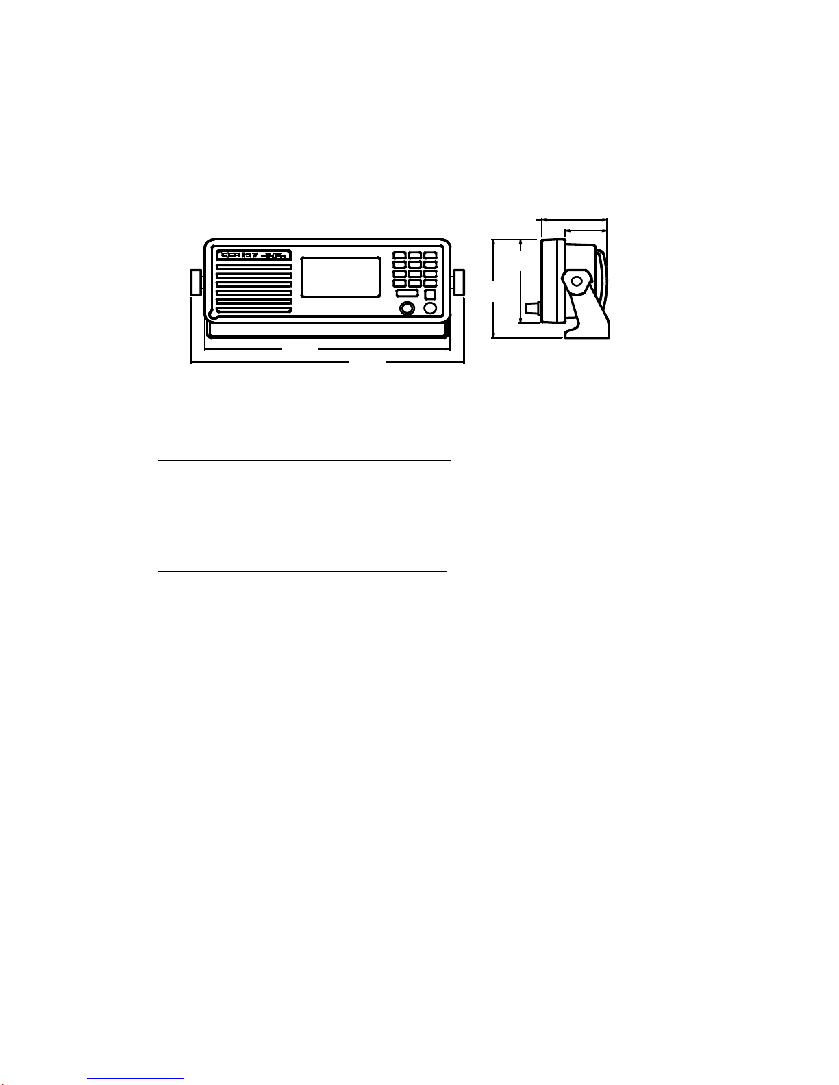
TECHNICAL FEATURES AND SPECIFICATIONS
Figure 1.1
ELECTRICAL SPECIFICATIONS
12 Vdc +30% -10% <1.0 – Amp Receive
<7.0 – Amp Transmit
WIRING DIAGRAMS Main Cable
Color Code Signal
1 - RED - 12 Vdc (+)
2 - BLACK - 12 Vdc (-)
3 - BLUE* - Audio Out
4 - ORANGE* - Internal Speaker (IN)
5 - YELLOW - (VDR) 600 Ohm Balanced
6 - GREEN - (VDR) 600 Ohm Balanced
7 - VIOLET - (VDR) Ground
8 - GRAY - AUX remote distress key
9 - BROWN - PTT
10 - WHITE/RED - Mute
11 -
WHITE - Microphone Input
12 -
SHIELD - Microphone Input GND
*NOTE: Audio Out – (BLUE) and Internal Speaker (IN) -
(ORANGE) wires must be connected in order for internal speaker
operation.
Dime
nsions:
3.6” H x 9.6” W x 2.8” D
Weight:
3 lbs (1.4 kg)
10.66
[270.8]
9.60
[243.8]
4.25
[108.0]
3.60
[91.3]
2.56
[64.9] 1.63
[41.5]

4
WIRING DIAGRAM Remote (SEABUSS) Cable
Color Code Signal
1 - BLACK - GND
2 - RED - 13.6V Switched
3 - VIOLET - Remote PTT
4 - GREEN - SEABUSS Data (+)
5 - BLUE - SEABUSS Data (-)
6 - YELLOW - SEABUSS Audio (+)
7 - BROWN - SEABUSS Audio (-)
8 - WHITE - ON-OFF Control
9 - SHIELD - GND
WIRING DIAGRAM Data Cable
Color Code Signal
1 - WHITE/BROWN - RS232 TxD Line
2 - BROWN/WHITE - RS232 RxD Line
3 - WHITE/ORANGE - RS232 GND
4 - WHITE/BLUE - NMEA Input (+)
5 - BLUE/WHITE - NMEA Input (-)
6 - WHITE/GREEN - NMEA Output (+)
7 - GREEN/WHITE - NMEA Output (-)
8 ORANGE/WHITE - No Connect
9 - SHIELD - GND

5
INSTALLATION
Flush Mount
Figure 1.2
Mounting Bracket
Figure 1.3

6
Physical Mounting:
Select a mounting location where the unit is easily accessed. Mount the
unit in the desired position using the provided Trunnion mount or flush
mounting kit. See Figures 1.2 and 1.3.
Power supply wiring:
CAUTION: Make sure that the provided fuse holder is installed on
the power cord between the radio and the power source, and that the
proper sized fuse (7.5A) is installed.
Use a 12 volt +30%/-10% (10.8 to 15.6VDC) DC power source for proper
operation. Do not exceed 16.0 volts. Direct connection to the battery is
recommended. Connect the heavy red wire, with in-line fuse installed, to
the positive (+) terminal and the heavy black wire to the negative (-)
terminal. Negative ground is required for the USA/Canada version of the
SEA 157S.
CAUTION: If the polarity of the power wires is reversed (Black to
positive, Red to negative), and power is accidentally applied to the radio,
the in-line fuse will blow. It is possible that damage could also occur to
some internal components. Application of voltages greater than 16.0 volts
will produce the same result. (Refer service to a qualified technician.)
Antenna wiring:
Use only the best available 50 ohm coaxial antenna cable and connectors.
The antenna must be vertically polarized. Check the antenna system for
less than 1.5:1 VSWR with an in-line wattmeter before final installation.
The antenna cable PL-259 connector should be tightly fastened to the
antenna connector on the back of the unit. All antenna connections should
be carefully protected from the weather.
7
1.0 Power On/Off
Momentarily press the PWR key to turn on the unit. The radio first
performs a diagnostic self-test, displaying any errors, then reverts to the
last channel selected.
To turn off the unit, hold the PWR key in until the display reads 'POWER
DOWN " (greater than 2 seconds), then release.
NOTE: The last volume, dim, squelch levels, and channel number are
saved when the unit is powered down using the PWR key.
2.0 KEYPAD FUNCTION AND DISPLAY LAYOUT
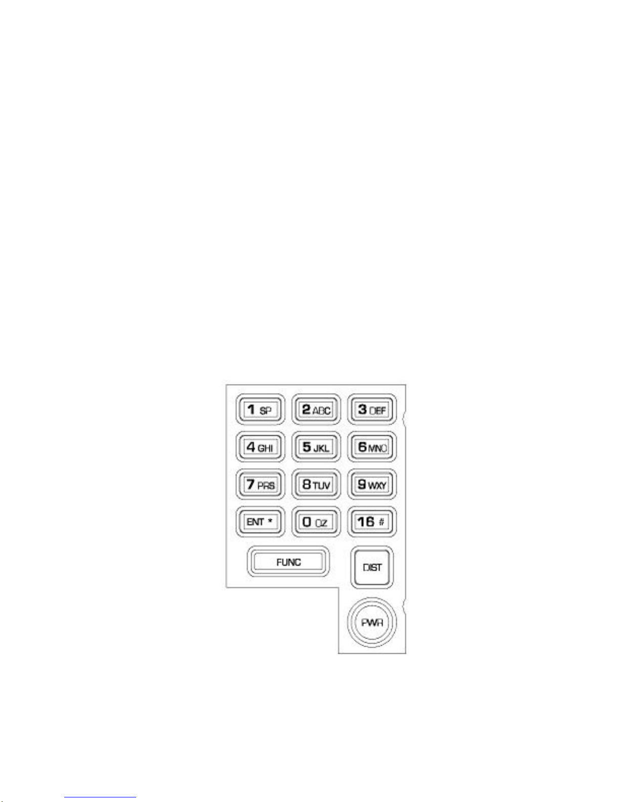
2.1 Keypad Layout
Figure 1.4
Keypad

8
2.2 Keypad Functions
1/SP Alpha/Numeric Entry – Space Character
2/ABC Alpha/Numeric Entry
3/DEF Alpha/Numeric Entry
4/GHI Alpha/Numeric Entry
5/JKL Alpha/Numeric Entry
6/MNO Alpha/Numeric Entry
7/PRS Alpha/Numeric Entry
8/TUV Alpha/Numeric Entry
9/WXY Alpha/Numeric Entry
0/QZ Alpha/Numeric Entry.
ENT/* Opens and Closes Edit fields. General acknowledgement of
Prompts that require user action. On the Primary Radio
Display, this key can be used to select the radio controls:
Volume, Channel, Squelch and the Back Light level.
DIST DSC Distress Call. Press for 5 seconds to initiate a Distress
call sequence.
16/# Go to CH 16 immediately. If pressed again, switches to CH
9. Active in all radio modes.
PWR Power on/off
FUNC Generally used to access the Soft Key Menu. Also used to
navigate through Menu Levels.
NOTE: During transmit, the keypad (1-0,FUNC, ENT*, 16 #) can be used to
send DTMF tones.

9
2.3 Soft Key Functions
Pressing the FUNC key will bring up the Soft Key Menu, which will be
displayed for five seconds. Pressing one of the number keys while the
Soft Key Menu is displayed will initiate the secondary function associated
with the key, as described below.
1 – DW Starts the Dual Watch. Starts the Triple Watch if held.
2 – SCAN Starts the MEM Channel Scan.
3 – SEEK Starts the All Channel Seek.
4 – PRI Switches to the Priority Channel.
5 – LIST Displays the channels in the Memory Scan List
6 – CH GRP
Toggle between USA/INT/WX channels. Last channel
in each list is remembered
7 – 1W Toggle between 1W and 25W
8 – DSC Transmit a DSC call. User will be prompted for type
of call to transmit
9 – SQL Squelch On/Off toggle
0 – MENU Opens the primary configuration menu
1
–
DW 2
–
SCAN 3
–
SEEK
4–PRI 5–LIST 6–CH GRP
7–1W 8–DSC 9–SQL
0–MENU

10
2.4 Display Layout
The Primary Radio Display will appear as shown below:
The display may contain any of the following elements:
USA Channel list indicator
INT International list indicator
WX Weather channel list indicator
PRI Priority channel
TX Transmitting
MEM Memorized channel
1W or 25W Power indicator
SCB Scrambler On
DSC DSC mode active
SQL Squelch state on/off
A Simplex USA channel
SCN Scan is active
DW Dual Watch is active
25W USA
Distress
38* 32.123N
112* 45.041W 12:13:00
16

11
3.0 BASIC OPERATION
3.1 Key Usage
Most of the radio functions are selected using the FUNC key. The phrase
“press FUNC-6” means to press and release the FUNC key, then press
and release the 6 key. Some functions are selected by holding a number
key for longer than 1 second. The phrase “press FUNC-6 for longer than 1
second” or “hold key” means to press and release the FUNC key, then
press and hold the 6 key for longer than 1 second, then release the key.
The radio will beep, if beep is enabled, when the key is pressed. On long
key holds a double beep will be sounded when the key has been held
down long enough to enable the secondary function.
While in the Primary Radio Display, the ENT key may be used to scroll
through and select the major radio controls: Volume, Channel, Squelch
and the display Backlight level.
3.2 Rotary Control
The rotary control of the SEA 157S is used for a number of radio
functions, such as adjusting the channel, volume, squelch and
backlighting from the Primary Radio display. The rotary control is also
used to navigate through menu selection or to move the cursor position
during edit operations.
When modifying radio controls on the Primary Radio Display the rotary
control will return to the volume setting state 5 seconds* after the last
adjustment is made. During Squelch adjustment, this time is extended by
5 seconds to allow for squelch on/off time. * Rotary control timeout time
is adjustable. See Paragraph 18.3.3.

12
4.0 SELECTINGA CHANNEL
4.1 Selecting Channel Lists USA/INT’L/WX
Pressing FUNC-6 will toggle the radio between the USA, INT’L and
Weather Channel Lists. The radio will go to the last used channel in the
selected list.
4.2 Selecting a Channel Using the Keypad
When the radio is in the Primary Radio Display, the numerical keys may
be used to select a channel directly. To immediately switch to a channel,
enter the two-digit channel number, including the leading zero for a single
digit channel. If a single digit is pressed, the radio will switch to that
channel following a 5 second pause.
For example, to go to channel 23 press 2,3 to switch to the channel
immediately. Press 0,5 to go to channel 5 immediately. Press 6 and pause
for 5 seconds and the radio will switch to channel 6.
4.3 Selecting a Channel Using the Rotary Control Knob
While on the Primary Radio Display, press the ENT key until “Change
Channel” is displayed, then use the rotary control to scroll through the
current channel list until the desired channel is displayed. Scrolling will
wrap around at either end of the list; for example, the display will wrap
from channel 88A to channel 1 when moving up through the list.
4.4 Selecting a Weather Channel
While in the WX channel list, press the ENT key until “Change Channel”
is displayed, then use the rotary control to scroll through the current
channel list until the desired channel is displayed. The channel number
can also be entered directly by entering it with the keypad.
4.5 Modify Channel Operation
While on the Primary Radio Display, press and hold the ENT key until
“Channel Operation” page is displayed. On this page there are several
controls available for the channel which include changing the name of the

13
channel, adding CTCSS tone option (See Paragraph x.x), make the
channel the Priority Channel and add/remove the channel from the Scan
List.
5.0 VOLUME ADJUSTMENT
The default rotary control mode is volume setting. In the Primary Radio
Display, simply turn the rotary control to adjust the volume from 0 to 15.
6.0 SQUELCH ADJUSTMENT
In the Primary Radio Display, pressing FUNC-9 will toggle the squelch
on and off, as indicated by the SQL flag in the display.
To adjust the squelch level, press ENT key until “Change SQL” is
displayed in the upper right corner of the display, then use the rotary
control to adjust the level as desired.
The radio returns to its normal operating state 5 seconds* after the last
squelch adjustment, or you may press FUNC to exit immediately.
* This time is influenced by the rotary control timeout time setting. See
Paragraph 18.3.3.

14
7.0 DIMMER LEVEL
In the Primary Radio Display, press the ENT key until “Change DIM” is
displayed in the upper right corner of the display. Use the rotary control to
adjust the display backlight to desired level, from 0 (off) to 15 (brightest).
8.0 CHANNEL 16/9
Pressing the CH16 key during most states of radio operation will return
the radio to CH16. Pressing CH 16 repeatedly will toggle the unit between
CH16 and CH9, except while transmitting.
9.0 TRANSMITTING
After selecting the desired channel, pressing the PTT switch on the
microphone will initiate transmission on that channel if it is allowed. The
TX display enunciator will light while transmitting. At the onset of PTT, a
five minute transmit timer* is started, and, if the transmission continues
longer than this period, the radio will emit four short beeps and return to
receive mode.
When transmitting on a 1W only channel, the power level may be
temporarily set to 25W if the ENT key is held while transmitting.
Pressing PTT while the radio is in other than normal receive mode, such
as volume level setting, Configuration Menu, or entering a channel
number, will cause the unit to exit the mode, return to the last selected
channel and begin transmitting immediately.
* Current FCC rules prohibit transmissions longer than five minutes in
duration.

15
10.0 DUAL/TRIPLE WATCH
10.1 Dual Watch
The SEA 157S has two watch modes available. Dual watch is initiated by
pressing FUNC-1 briefly while on the primary monitoring channel; the
Dual Watch channel will then be checked every 1.0 second for activity. If
there is activity on Dual Watch channel, the radio will hold on that
channel until there is no activity or 5** seconds. The Dual Watch channel
can be set to either CH16 or the Priority Channel in the Dual Watch setup
menu option (See Paragraph 18.1.1). The channel number display will
indicate which channel the unit is operating on. Pressing any key or PTT
will exit dual watch and switch to the current channel. The DW Flag will
be displayed when function is active.
10.2 Triple Watch
The Triple Watch function monitors three channels - CH16, the Priority
Channel and a third selected channel. To initiate the Triple Watch feature,
select a Priority Channel (Paragraph 13.0), select the third channel
(Paragraph 4.3), then press FUNC-1 for more than one second. To exit the
mode press any key or PTT.
11.0 SCAN/SEEK
The SEA 157S contains both Scan and Seek functions. Seek mode scans
all channels in the selected Channel List (USA, INT, or WX), whereas
Scan monitors channels that are members of a user-programmed Scan
List.
11.1 Scan
The Scan function is initiated by pressing FUNC-2. The radio will scan
the user-programmed list of scan channels, stopping on any active
channel, and remaining on that channel for 5** seconds after the channel
becomes inactive. The SCN Flag will be displayed when the function is
active. Pressing the “ENT” key will force the radio to temporarily skip an
active channel and continue scanning.

16
** 5 seconds is factory default. This time may be adjusted in the Radio
Controls menu (Paragraph 18.3.2).
11.2 Scan List – Add/Delete Channels
Press and hold the ENT key until the “Channel Operations” page is
displayed. If the channel is not in the scan list the bottom selection will
be “Add to Scan List”, if the current channel is in the scan list then the
bottom selection will be “Del from Scan List”.
11.3 Scan List – View
To view which channels are in the scan list press FUNC-5. Each channel
in the scan list will be display for 1 second until the end of the list.
11.4 Seek (All Scan)
Seek is started by pressing FUNC-3. The radio will scan all the channels
in the current Channel List. The SCN Flag will be displayed while the
function is active. (Paragraph 4.0)
12.0 TRANSMIT POWER
Pressing FUNC-7 toggles the transmitter power level on channels that
allow 25w transmission. On channels that only allow 1W this function has
no effect. When transmitting on a 1W only channel the “FUNC” key may
be held down while transmitting to temporarily switch to 25W. The
1W/25W display flag will indicate the current transmit power level.
13.0 PRIORITY CHANNEL
Pressing FUNC-4 switches the radio to the programmed Priority Channel.
To select the current channel as the Priority Channel, press and hold the
ENT key until the “Channel Operation” page is displayed. Use the rotary
control to move the cursor to the “Make PRI Channel” and then press the
ENT key. The Priority Channel is also used by the Triple Watch mode
and the Priority Scan and Seek modes.
Other manuals for 157S
1
Table of contents


