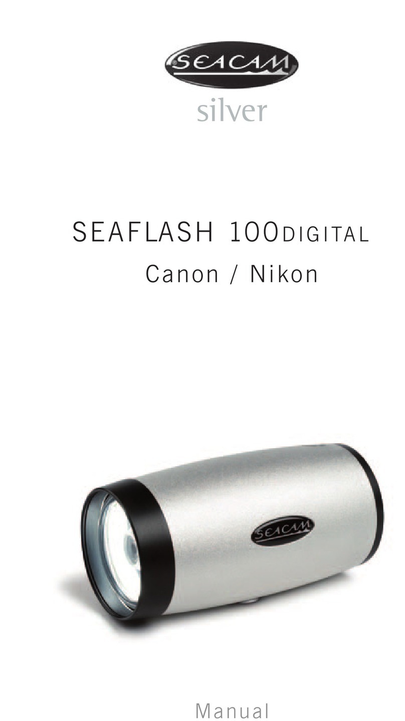
Seacam SEAFLASH 160DIGITAL User manual

silver
USER MANUAL
SEAFLASH 160DIGITAL
SEAFLASH 160OFFSHORE
CANON TTL / NIKON TTL / SLAVE TTL

2
Overview
Trademark Information
CANON is a registered trademark of CANON INC.
NIKON is a registered trademark of NIKON CORPORATION.
SEACAM is a registered trademark of SEACAM.
Thank you for your confidence in our products. This manual has been written carefully
to help you enjoy your high-quality products. Read these instructions thoroughly
before use and keep it at hand when having questions. Take a few moments to
familiarize yourself with the functions and handling. If you read the manual carefully,
nothing shall keep you from taking excellent underwater pictures.
This manual provides the complete operating instructions for your SEAFLASH
160digital and SEAFLASH 160offshore. The document can be downloaded at
www.seacam.com/en/service/downloads/manuals or from the QR Code enclosed.

3
Safety Instructions 5
General Description 7
Controls and Parts 9
Compatible Cameras 11
Quick Guide 12
Battery Management and Maintenance 14
1. General Information
2. Battery Recharge
3. Battery Maintenance and Refreshing
Pilot Light 17
Shooting Mode – Cable 19
1. E-TTL, I-TTL, film-TTL
2. Manual Mode
3. HSS High Speed Syncronisation
4. 2nd Curtain Flash Operation
5. Stroboscopic Mode
6. Dual / Multiple Flash Operation
Shooting Mode – Optical & Slave 25
1. Optical TTL
2. Optical Manual Mode
3. Optical Stroboscopic Mode
4. Optical Dual / Multiple Flash Mode
5. Front Slave Sensor
S.O.S. Safety Mode 30
Contents

4
Setup Menu 31
1. Pilot Light
2. Display
3. Prelamp
4. Camera types & Multiple flash
5. Other Settings & Data
Firmware Upgrade 34
1. Procedure
2. Upgrade Error Codes
General Error Codes 38
Maintenance 39
Accessories 40
1. Standard Accessories
2. System Accessories
3. Flash Arm System
Technical Details 49
Environmental Information 50
Warranty 51
General 51
Contents

5
Safety Instructions
Before using your product, please read the following safety precautions carefully
and thoroughly to ensure correct and safe use and to help prevent damage to your
SEACAM product or injury to yourself or others.
• Never try to open the unit by yourself – the internal high voltage is potentially lethal
and could lead to personal injury. The unit may only be serviced by an authorized
SEACAM Service Center.
• Do not fire the flash unit directly into the eyes of someone that is at close range, as
it could seriously damage the retinas of their eyes.
• Use only SEACAM accessories and original TTL- / fiber optical cable which are
delivered with the flash.
• Use only the battery pack specified and especially made for this unit. Always follow
the warnings and instructions printed on the battery pack.
• Do not short-circuit or disassemble the battery pack, because this could cause the
batteries to leak corrosive liquids, generate heat or explode.
• Do not throw or apply strong physical shocks to the batteries as this could cause
batteries to leak corrosive liquids, generate heat or explode.
• Handle used battery packs as instructed and follow the environmental information
in this manual.
• Use only the original 100V – 240V power supply or 12V power adapter cable to
charge the unit.
• Never use two flashes together with a digital camera in a different way than recom-
mended in this manual. Not strictly following the correct connections can result in
a damage of the strobes and the camera.

6
• Before using the flash with a camera brand not listed in this manual contact
SEACAM.
• Never connect a power supply or battery charger to the synchro connection of the
unit or to the USB Adapter.
• Do not remove the battery pack from the battery container if the unit is still switched
on.
• Never use this flash together with a different flash brand. Enquire about its compa-
tibility and connections especially when using electrical connections. Not following
this recommendation can result a damage of the unit or the camera used.
• Never shoot the flash directly into the lens of a digital camera. This can damage the
camera picture sensor.
• Always prevent water or moisture from entering into the battery container, to the
batteries, sockets and plugs. Close the battery carefully container before using the
flash underwater.
• Never exceed the maximum depth rate. This will cause a structural damage of the
unit.
• Make sure that the thread of the ball adapter is no longer than 7 mm. Longer
threads can cause massive damage to the housing if force is used.
• Always use the flash as instructed in this user manual. Not paying attention to the
recommendations of this user manual can cause damage to the unit or to the used
camera and excludes warranty claims.
Safety Instructions

7
The SEAFLASH 160digital and SEAFLASH 160offshore are different in the maximum
rate of depth only. The standard depth rate is -80 m / -240 ft. The offshore depth rate
is -200 m / -600 ft. All electronic features and the accessories are the same. In the
further manual both strobes are called SEAFLASH 160digital.
SEAFLASH 160digital SEAFLASH 160offshore
The SEAFLASH 160digital is fully controlled by a microprocessor. Some of the
significant advantages of using these processors are the possibility of managing digital
communication on a serial bus with a digital camera and easily updating the firmware
through a USB connection.
Thanks to the special electronics, the SEAFLASH 160digital is equipped with many
special features. These features can be programmed individually and adapted to your
needs. In order to make it easier for you to operate the strobe right from the start, the
device is delivered with proven basic settings (default).
An additional advantage is the ability to rotate a graphical digital display (4) which is
the perfect interface between the user and the flash. The bright OLED display offers a
high contrast ratio for an improved visibility.
This flash unit works in TTL and manual mode with Nikon and Canon cameras.
Cameras with fiber optical connection as well as a slave flash, triggered by an
integrated optical sensor. Fast synchronization FS up to 1/8000 and rear curtain
operation are also a standard feature.
General Description

8
The SEAFLASH 160digital features Canon e-TTL, Nikon i-TTL, multi-TTL, Film TTL
and manual power adjustment, TTL mode exposure adjustment +3 to -3 aperture
in 1/3 steps. Manual mode works in 14 different power settings from 1/1 to 1/64 -
minimum power settings in 0,5 aperture steps from 1/1 to 1/64.
A new stroboscopic mode with 2-15 selectable pictures, automatically spaced within
the camera synchro speed or manual time mode is also featured in the firmware.
In order to further improve battery life and to make the battery management very fast,
easy and safe, a lot of attention was given to the battery pack electronics.
A high-quality NiMH changeable battery pack with an integrated charging unit is
used for this unit. Delivered with a 100-240V power supply and 12V cable adapter it
offers quick charge, controlled by –ΔU power off, a charging level display and a total
recharge time of 180 min.
This user manual contains important information. By reading it carefully you will learn
about the many advantageous features of the SEAFLASH 160digital that will help you
taking great pictures.
CANON or NIKON / FIRMWARE RELEASE / SERIAL NUMBER
When switching ON the unit you first see a 3 part battery symbol indicating the
battery capacity status and the flash type followed by the NIKON or CANON
identification.
When switching OFF the unit you see the serial number on the left and the actual
Firmware release number ( v.01) on the right side down.
CANON or NIKON / FIRMWARE RELEASE / SERIAL NUMBER
When switching
ON
the unit you first see a 3 part battery symbol indicating the
battery capacity status and the flash type followed by the NIKON or CANON
identification.
When switching
OFF
the unit you see the serial number on the left and the actual
Firmware release number ( v.01) on the right side down.
General Description

9
Control Panel
1Power Switch /
Mode selector
2Rotary Switch –
multi purpose
3Push Button / Pilot Light /
Input control
4OLED Display
5Multicolor Ready Light
Indicator LED
6Safety Lock Button
7Battery Compartment / Cap
Front
8Front Slave Sensor
9Flash Bulb / Reflector
10 LED Pilot Light
Controls and Parts
7
1
5
3
2
4
6
10
8
9

10
Connections
11 S6 Synchro Socket
12 Fiber Optical Socket
13 M8 Connection Thread
14 Macro Protection Ring,
removable
Battery Pack
15 Power Adapter Socket
16 Recharger LED Indicator
17 Minus (-) Battery Pin
18 Plus (+) Battery Pin
19 Battery Pull Ring
Controls and Parts
M8 Connection Thread
Macro Protection Ring,
11
12
13
14
16
15
18
17
19

11
The SEAFLASH 160digital is suitable for CANON and NIKON digital and film
cameras, in e-TTL, i-TTL, film -TTL and in manual mode. All special functions as,
+/- flash compensation, automatic AF- light, pre-exposure lamps, automatic standby,
2nd curtain exposure etc. are supported. Other camera brands can be used in manual
mode.
Cameras supporting optical triggering can be used with the SEAFLASH 160digital in
manual and TTL mode by using a fiber optic cable. Optical TTL is available only if the
setup of the camera and housing allow it.
With the power switch (1) you have 6 different shooting modes to choose from. All
these modes require different kind of connections. The SEAFLASH 160digital offers 3
different inputs for your demands.
S6 SYNCHRO SOCKET (11)
FRONT SLAVE SENSOR (8)
FIBER OPTICAL SOCKET (12)
Compatibile Cameras

12
The SEAFLASH 160digital is easy to set up and use with only a few steps.
Macro protection ring and M8 Ball Adapter
For macro photography, leave the macro protection ring (14) on the unit to reduce the
light angle to approximately 90°. For the required illumination of wide-angle lenses,
remove the macro protection ring (14) from the flash by turning it to the left. When
installing, make sure that the protection ring snaps into the correct position by turning
it over the resistance so that it cannot be lost.
An M8 ball adapter is required to attach a flash arm to the flash unit. Use the original
SEACAM M8 ball adapter (not included) – it is mounted onto the M8 connection thread (13).
ATTENTION!
If you are using balls from other manufacturers on the flash unit, make sure that
the thread of the ball is no longer than 7 mm. Longer threads can cause massive
damage to the housing.
Single flash operation
1. Fit a fully charged battery in the battery compartment and close it with the cap.
2. Connect the flash to the camera by wire or optical cable at the S6 synchro (11)
or fiber optic socket (12)
3. Set the power switch (1) to TTL, powering up the strobe.
4. Select desired flash input mode: press push button (3) for 2 seconds to
switch between sync inputs:
CB Cable
OC Optical Cable
SL Front Slave Sensor
5. Select Shooting Mode with power switch (1)
TTL TTL mode
MAN Manual mode
MOD Stroboscopic mode
Quick Guide
ATTENTION!
If you are using balls from other manufacturers on the flash unit, make sure that
the thread of the ball is no longer than 7 mm. Longer threads can cause massive
damage to the housing.

13
In TTL mode, correct the exposure if needed +/- with the rotary switch (2) 1/3
aperture per step.
In MAN manual mode, adjust the power setting with the rotary switch (2) – increasing
the power rotating clockwise and decreasing the power rotating counterclockwise.
Half aperture per step.
Multiple flash operation
If more than one unit has to be connected to the camera with a cable connection,
set the main strobe to MASTER MODE and all the other flashes to SLAVE MODE.
To select SLAVE mode, enter SET with the power switch (1), select MASTER / SLAVE
set up with the rotary switch (2), activate it with push button (3), set it to SLAVE with
rotary switch (2) and confirm it with push button (3). The unit will then reboot in
SLAVE mode. When in SLAVE mode, an s appears on the display after the CB label:
CBs – it identifies the SLAVE units.
Feature
All flash settings are stored in the internal memory and have to be set only once.
If a cable connection is used to synchronize the strobe with NIKON or CANON
cameras the system is fully ready to start, no other adjustments are required. CB will
be shown automatically in the display when the camera is connected and activated.
If a fiber optic cable is used to synchronize the strobe, maybe an additional set up
could be required once – due to a great number of possible combinations of different
hardware. If this is the case, please refer to the specific chapter in this manual (9) and
the manual of the camera used.
Quick Guide

14
The removable SEAFLASH 160digital battery pack is located under the battery
compartment cap (7). To remove the cap, press the safety lock button (6) and turn
to the left. Close it by turning it to the right. When closing or opening, the battery
compartment cap will automatically be pushed in or pulled out from the container.
Always prevent water or moisture from entering into the battery container or to the
battery pack. Ensure you close the battery compartment (7) completely before using
the flash underwater.
IMPORTANT
Maintain / check the O-ring at the battery compartment cap (7) always when
opening. Clean and grease the sealing surface regularly. Close the battery
compartment cap (7) completely until you hear a CLICK sound.
Feature
The battery compartment is completely sealed. In case water enters due to an
incorrect battery compartment cap positioning or an O-ring failure, the electronic
will not be floated. Only the battery pack and battery contacts can be damaged.
Tip
When floating occurred, remove the battery pack immediately, rinse with fresh water
and dry the battery compartment completely. By using a spare battery, you can
continue shooting. Send the unit to a SEACAM service facility for a complete check
as soon as possible.
The battery fits only in one position. You can remove the battery pack by pulling up
the battery pull ring (18). When fitting in the battery pack, ensure that the battery
pull ring (18) is tilted down. The battery pack is made of special NiMH batteries. It is
equipped with a built-in electronic to make battery management easy, fast and safe.
By switching on the flash, the user can read the indication of the battery status on
the OLED display (4).
Battery Management and Maintenance

15
Battery Management and Maintenance
ATTENTION!
Never remove the battery pack from the battery compartment when the flash unit
is still switched on! To prevent slow deep discharge, never leave the battery in the
flash when it is not in use!
1. General Information
During normal operation, a microprocessor checks the battery status and shows it
through a three-part battery symbol at the top of the OLED display (4). In order to get
a more accurate measurement, it is advised to release the flash 2 or 3 times at full or
half power. This operation will give a more accurate status of the battery energy level.
When the battery is completely discharged, an alarm is emitted and the display shows
a blinking empty battery symbol before automatically shutting off to avoid battery deep
discharge.
2. Battery recharge
Prior to first use, the battery must be fully charged before disconnecting it from the
power supply. The battery can be recharged also if it has not been fully discharged.
For charging, the battery pack has to be removed from the battery compartment (7)
and connected to the power supply.
After connecting the power supply or 12V cable power adapter to the power adapter
socket (15), the charge process starts and the control LED (16) starts to blink.
When the charging cycle ends, the control LED (16) is permanently lit and the battery
enters into trickle charge. It can now be disconnected from the power supply.
It takes approximately 180 min for the empty battery to fully recharge. If the battery
electronic detects an error, the charging process is stopped immediately and the
control LED (16) starts to blink at a high frequency. In this case, disconnect the
ATTENTION!
Never remove the battery pack from the battery compartment when the flash unit
is still switched on! To prevent slow deep discharge, never leave the battery in the
flash when it is not in use!

16
Battery Management and Maintenance
power adapter and wait for the battery to cool down. If the control LED (16) continues
to blink at a high frequency, the battery might be defective and must be serviced or
replaced.
3. Battery maintenance and refreshing
As for all NiMH batteries, we advise to fully discharge the battery, when possible,
before recharging. To discharge the battery, leave it inside the flash and switch it on,
setting the pilot lamp on high power. The flash will automatically shut off when the
battery is empty. The battery performance will increase after a few full discharge /
recharge cycles.
In order to keep and maintain the maximum energy level of the battery pack when it
is left inactive for a period of time, it should be charged and discharged as regularly as
described above. A few full charge/discharge cycles (3-4) are necessary to refresh the
batteries for perfect conditions if they have been stored for some time.
Tip
We recommend to repeat this procedure every month when the unit is not in use.
IMPORTANT
Never try to recharge a fully charged battery pack in order to avoid a battery
overcharge.
ATTENTION!
Never perform a series of full power shoots to discharge batteries. This will
decrease the flash bulb life and can also result in a flash damage. Never short-
circuit any battery terminals as it will damage the battery pack.
ATTENTION!
Never perform a series of full power shoots to discharge batteries. This will
decrease the flash bulb life and can also result in a flash damage. Never short-
circuit any battery terminals as it will damage the battery pack.

17
Pilot Light
A high efficiency power LED (10) produces bright coaxial pilot light with a light beam
of 10° and allows an easy and perfect setting of the flash. The light intensity can be
set in 25 different steps to fit personal requirements and preferences.
The pilot light is switched ON/OFF by the push button (3) and the settings can be
adjusted on 2 different light levels. For the first level, press the push button (3) once,
press a second time and you get to level 2. Pressing a third time switches the pilot
light off again. The two power levels are customizable – go to pilot light custom set
up below.
Feature
When the flash is connected to a digital camera, the automatic pilot light feature
is available. The pilot light turns on automatically when the camera auto focus
system needs more light to work.
In all shooting modes, the pilot light is automatically switched off while the camera
takes the picture in order to avoid interference with the flash. The pilot light turns on
again as the camera shutter stops. Automatic turn-on is limited to 2”. For a shutter
speed slower than 2”, the pilot light has to be turned off manually before taking the
picture.
Pilot Light Custom Setup
Selecting the set-up menu SET with the power switch (1), the pilot light can be
configured as desired.
To do so, go to the desired menu line, activate the control line with the push button
(3), adjust the value with the rotary switch (2) and save the setting with the push
button (3).
AF Assist ON / OFF (default ON)
Automatic Pilot Light for a better autofocus function can be activated or deactivated.

18
Pilot Light
PL High PL Low value … 25 (default 20)
PL Low PL High value … 01 (default 10)
Light intensity for step 1(Low) and step 2(High) can be set in 25 different steps.
PL Stb ON/OFF (default OFF)
The pilot light can be switched off automatically when the connected camera enters
into standby mode and will turn on again as camera is reactivated.
IMPORTANT
The connected camera will only activate the Autofocus Light if set properly:
On CANON cameras, set the AF selector to Sand select single shooting mode.
On NIKON cameras, set the AF selector to S or M. There is no automatic function
in C, select center area for autofocus.

19
Electrical Synchro Connection
It is highly recommended to use a wire synchro connection with Nikon and Canon
digital cameras to ensure the precise, full performance and accessibility of all features
from the camera-flash setup. For this purpose, use our highest quality S6 synchro
cable and connect the S6 synchro socket (4) with your camera system. As soon as
you connect the flash unit to the camera and it is active, the display for the cable mode
CB appears automatically at the top of the display (4). If necessary, this mode can be
changed manually with the push button (3).
The different shooting modes are selected with the main switch (1):
TTL TTL
MAN Manual Mode
MOD Stroboscopic Mode
The ready LED (5) shows RED when in TTL mode and GREEN in MAN (manual)
mode. The power levels are adjustable with the rotary switch (2).
1. i-TTL , e-TTL, film-TTL Mode
Set the power switch (1) to TTL and the ready light LED (5) will be RED. The power
required from the flash is calculated by the camera to obtain the correct exposure.
An additional manual correction from +/-3,0 in 0,3 aperture steps is available if
necessary, using the rotary switch (2).
The display indicates the correction: The number 0.0 for no correction. Numbers with
minus sign (-) for a negative correction and plus sign (+) for a positive correction.
After each shot in TTL mode, the display blinks and indicates the released power for
8 seconds. The power is indicated in 14 aperture steps and half steps: 1/1 for full
power 1/1 -5 for a half step less, 1/2 for half power, 1/2 -5 for half steps less, down
to 1/64 -5.
Shooting Mode – Cable

20
When the flash delivers at full power, but less than the camera requires, the user is
advised of a possible underexposure with an audible alarm and 1/1 blinking on the
display.
Feature
Knowing the delivered power allows you to identify whether it is still possible to
further open or close the aperture.
2. MAN - Manual Mode
Set the power switch (1) to MAN and the ready light LED (5) will be GREEN. The
power of the flash is selected with the rotary switch (2) and the display indicates this
power in 14 aperture steps and half steps: 1/1 for full power 1/1 -5 for half steps less,
1/2 for half power, 1/2 -5 for a half step less, down to 1/64 -5.
Feature
The rotary switch (2) with accurately defined steps, combined with a clear reading
on the display allows for a fast and accurate power setup.
3. HSS - High Speed Synchronization
HSS is available in TTL and in MAN mode and will operate at up to 1/8000 camera
shutter speed. You are able to set this mode only if the camera is active and connected
to the strobe. When HSS is activated, the display shows FP.
On NIKON cameras, the HSS mode is automatically activated by the camera when
the shutter speed is set over 1/250. The display shows FP.
On CANON cameras, HSS can be activated by pressing the push button (3) 2
times for more than 2s. The display shows FP.
Shooting Mode – Cable
This manual suits for next models
1
Table of contents
Other Seacam Camera Flash manuals
