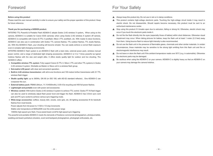
Godox MF12 User manual

Instruction Manual
Macro Flash
705-MF1200-01
Made in China
: 2
: 0755-29609320(8062) : 0755-25723423 : godox@godox.com
godox.com
Add: Building 2, Yaochuan Industrial Zone, Tangwei Community, Fuhai Street, Bao’an District,
Shenzhen 518103, China Tel: +86-755-29609320(8062) Fax: +86-755-25723423
GODOX Photo Equipment Co., Ltd.
QCPASS

OLED
TTL
M
2.4G
C.Fn:
02
03
04
06
06
09
09
10
10
12
14
14
14
14
15
16
MF12
MF12TTLM()
S1/S2
LED
MF12
- 01 -
主要特点:
TTLM(MF12)
S1/S2
LED
2.4G
OLED
TYPE-C
5001.7
- 02 -

1.
2.
3.Type-CUSB()
4.
5.
6.
7.
8.
•
50
()
,
- 03 - - 04 -

•
1.
2.
3.
4.
5.
6.SET
7.
• OLED显示屏
TTL
S1/S2
M
32
CH
TTL
E
32
CH
M
E32 + 0.9
1/
32
CH
M
E32 + 0.9
1/
S1
32
CH
M
E32 + 0.9
1/
S2
×1
:
XProX1TTLX2TTLMF-AR(49mm52mm
55mm58mm62mm67mm72mm77mm)
注:MF12MF-AR*149mm
52mm55mm58mm62mm67mm72mm77mm
×1
Type-CUSB×1
×1
×1
×1
()
MF-11T×1
×1
- 05 - - 06 -
×1×1
()
MF-11C×1

•
1.MF12
2.
•()
1.MF12()
MF-AR
6
2.MF12
3.
(849mm52mm55mm58mm
62mm67mm72mm77mm)()
4.
- 07 - - 08 -

•
1.,
2.,
3.Type-CUSB,(55)
•
3
2
1
,,10
:(10),
STBY,SET
30min/60min/90min/OFF.
30/60/90)
C.Fn-STBY
UNLOCK
1.:
1.1.<>LED
1.2.
SET
2.:<>
2.1.:
10(1~10)
MF12TTLM()2
TTL
,
TTL
M()
<>MODE
SETTTL
M()
TTL
TTL<>TTL
10
C.Fn
32
CH
TTL
E
Ver 0.5
PHOTOC
WL
MODE
TTL
- 09 - - 10 -

M
1/1281/10.1
1.M<>
M
2.M
M<>
C.FnPHOTOCSET
S1S2
1.S1
S1
2.S2
S2TTL
2
MS1/S2
32
CH
M
E32 + 0.9
1/
C.Fn Ver 0.5
WL
MODE
S1PHOTOC
32
CH
M
E32 + 0.9
1/
S1
(2.4G)
MF122.4GXX1XProX2
/////TTL
(X1T-N)(X1T-C)(X1T-S)
MF12-TTL,!
WL)
<>C.Fn
WLSET:
OFFON
C.Fn Ver 0.5
PHOTOC
MODE
ON
WL
(CH)
(CH)
<>C.FnCH,SET
(01-32,
SET
C.Fn Ver 0.5
GR
32
ID
CH
C.Fn Ver 0.5
E
ID
CH
(GR)
C.FnGR,SET
(A/B/C/D/E,
SET
GR
(PHOTOC)
- 11 - - 12 -

C.Fn Ver 0.5
99CH
ID
C.FnID,SET
ID(OFF/01~99,
SETID
GR
ID
:
1.2.4G(2.4Gwifi)
•CH(+10)
2.4G
2.(
)
•TTLM(TTL
)
3.(<0.5m)
•:
X12
X2XproC.Fn-DIST0-30m
4.
•(1.5V)
2.4G:
C.Fn:
1.<>C.Fn
2.SET
3.SET<>
MODE
PHOTOC
WL
GR
CH
ID
STBY
S1/S2
ID
M
TTL
OFF
S1
S2
ON
OFF
A/B/C/D/E
1~32
OFF/01~99
OFF
30min
60min
90min
S1
S2
A/B/C/D/E
1~32
OFF01~99
30min/60min/90min
- 13 - - 14 -
50

(1/1)
LED
2.4G
ID
TYPE-C
MF12
3.7V/6.29W
GN=16.1±0.1
12W
81/128~1/1
1~10
OLED
S1/S2
TTLM
1/1200s~1/34000s
ON/OFF
321~32
5A/B/C/D/E
OFF/01~99
30m
5V2A
500
0.01~1.7
30min/60min/90min30min/60min/90min
OFF
81*76.5*64.3mm
144g
•
•
•
•
•1,1
•,
•,
•
- 15 - - 16 -

Forward
Warning
Names of Parts
Body
Control Panel
OLED Display
Included Items
Optional Accessories
Battery
Battery Management
Modeling Lamp
Flash Mode Selection
TTL Auto Flash Mode
M Manual Flash Mode
Wireless(2.4G) Transmission
C.Fn: Setting Custom Functions
Reset Function
Forced Shutdown Function
Over-Temperature Function
Technical Data
Maintenance
Foreword
Thank you for purchasing!
MF12 is a mini macro flash.
Functionally, MF12 is equipped with two flash modes: TTL automatic flash mode and
M manual flash mode. With S1 / S2 secondary optic triggering mode, no additional
command signal or external remote control, direct trigger flash, convenient. Allocated
with always-on LED modeling light, it provides modeling light anywhere anytime,
which can also be used as a background light, hair light, or daily lighting.
In terms of structure, MF12 adopts professional optical lens design, which has
stronger focusing effect and ensures even distribution of shooting light effect. Built-in
rechargeable lithium battery, it is convenient for outdoor shooting and travel shooting.
Menu easy to operate, compact and light-weight size ensure it can be put into pocket
with great portability.
This mini flash is ideal for macro photography of animals and plants, food, jewelry,
oral images and so on.
18
19
21
22
22
25
25
26
26
28
30
30
30
30
31
32
Contents
Main Features
• Equipped with TTL automatic flash mode and M manual flash mode
• Having S1 / S2 scondary optic triggering modes
• Using a constant light LED modeling Light
• Adopted professional optical lens which offers more even lights
• Built-in 2.4G wireless X system
• Selecting the clear OLED display
• With built-in lithium battery which can be charged through Type-C port
• Max.1.7s recycle and 500 full power pops
- 17 - - 18 -
Warning
Always keep this product dry.
Do not disassemble. Should repairs become necessary, this product must be
sent to an authorized maintenance center.
Keep out of reach of children.
Stop using this product if it breaks open due to extrusion, falling or strong hit.
Otherwise, electric shock may occur if you touch the electronic parts inside it.
Do not fire the flash directly into the eyes (especially those of babies) within
short distances. Otherwise visual impairment may occur.
Do not use the flash unit in the presence of flammable gases, chemicals and
other similar materials. In certain circumstance, these materials may be
sensitive to the strong light emitting from this flash unit and fire or
electromagnetic interference may result.
Do not leave or store the flash unit if the ambient temperature reads over 50.
Otherwise the electronic parts may be damaged.
As this product do not have waterproof function, please take measures of
waterproof in rainy or damp environment.
Turn off the flash unit immediately in the event of malfunction.
Names of Parts
Body
1. Light Body
2. Wireless Sensor
3. Type-C USB Port(only for charging)
4. Reset Hole
5. Angle Adjusting Bracket
6. Push Button of Bracket
7. Lens
8. Modeling Lamp
- 19 - - 20 -

• Control Panel
1. Display
2. Menu Button
3. Power Switch
4. Modeling Lamp Button
5. Test Button
6. Set Button
7. Select Dial
TTL Autoflash
S1/S2
M Manual Flash
32
CH
TTL
E
32
CH
M
E32 + 0.9
1/
32
CH
M
E32 + 0.9
1/
S1
32
CH
M
E32 + 0.9
1/
S2
• OLED Display
Included Item
Cold Shoe x1
Optional Accessories
The product can be used in combination with the following optional accessories,
so as to achieve best photography effects: XPro, X1 and X2 TTL flash trigger,
MF-AR adapter ring, camera lens adapter rings kit (49mm, 52mm, 55mm, 58mm,
62mm, 67mm, 72mm, 77mm), etc.
Names of Parts
Color Filter
Holder x1
Note: MF12 Two-light Kit is not only including above items but also including 1 unit MF-AR Adapter
Ring and 8 pieces lens adaptor rings (Diameters of 49mm,52mm,55mm,58mm, 62mm,67mm,72mm,
77mm).
Light Body x1
Extreme Close-Up
Positioning Adapter x1
Color Effects
Set MF-11C x1
Type-C USB
Cable x1
Carry Bag x1 Instruction
Manual x1
- 21 - - 22 -
Flash Stand x1
Color Temperature
Adjustment Set
MF-11T x1
Color Filter
Bag x1

1. Press and hold down the push button of
MF12’s fixing bracket. Then, aim one end
of the cold shoe into the end of bracket and
slide it to install until a “click” can be heard.
2. Attach the cold shoe onto the hotshoe of
camera firstly. Then, turn the locking ring
and lock them.
Install Accessories
1. Aim the socket of MF12 into the sliding
block and push it until a“click” can be
heard. One adapter ring can install 6 lights
at most.
• How to Use Adapter Ring (Optional)
2. MF12 can be rotated leftwards or
rightward by pressing the push button of
bracket.
3. Choose the optional adapter ring(8
different diameters of 49mm, 52mm, 55mm,
58mm, 62mm, 67mm, 72mm, 77mm, etc.)
whose size is suitable for the neck strap of
camera lens. Install the camera’s adapter
ring onto the MF-AR adapter ring.
4. Attach the adapter ring onto the camera
lens.
• How to Install Cold Shoe
- 23 - - 24 -

MF12 flash has two modes: TTL autoflash and M manual
flash. In TTL mode, the camera and the flash will work
together to calculate the correct exposure for the subject and
the background.
The main subject is correctly exposed regardless of
background brightness. This is useful when you want to
highlight the main subject or make exposure compensation.
In Manual flash photography, you select the aperture and flash
output level. In this way, you can control the exposure and
flash shooting distance when shooting subjects where the
correct exposure is difficult to obtain in the TTL auto flash
mode.
Short press the < > menu button and turn the select dial to
choose MODE. Then, short press the SET button and turn the
select dial to choose TTL or M mode. Then, short press the
SET button to exit from Mode Selection.
1. Modeling lamp power ON/OFF:
1.1. Short press the < > button to control the on/off of LED
modeling lamp.
1.2. Long press the < > button to enter the modeling lamp
interface and then short press SET button to on/off modeling
lamp.
2. Modeling lamp setting: long press the < > button to enter
modeling lamp interface.
2.1 Brightness setting: turn the select dial to setting the
brightness value from 1 to 10 levels.
Battery Level Indication
3 grids
2 grids
1 grid
Blank grid
is displayed
Meaning
Full
Middle
Low
Low battery, please recharge it.
The battery level is going to be used out immediately. And the flash will auto
power off in 10 seconds. Note: please recharge the battery as soon as possible
(within 10 days). Then, the battery can be used or be placed for long period.
When using off the camera, it is recommended to turn off the “auto power off” mode through
C.Fn-STBY of custom setting functions.
UNLOCK
10
C.Fn
32
CH
TTL
E
Ver 0.5
PHOTOC
WL
MODE
TTL
Battery
1. This adopts Li-ion battery which is non-detachable.
2. It is reliably safe. The inner circuit is against overcharge, overdischarge, overcurrent, and
short circuit.
3. Take only approx. 55 minutes (within 1 hour) to fully charge the battery by using the
5V/2A charger.
• Battery Level Indicator
Power Management
Please turn off the power if not used for a long time.
Auto Power off Mode Setting
Press the menu button, turn the Dial to select STBY, press the
SET button, and then turn the Dial to select 30min/60min/
90min/OFF. After setting the auto power off mode, the flash will
automatically shut down when unattended operation for a long
time(more than 30/60/90 minutes). When it is automatically
shut down, please press the power on button to restart it, the
boot animation appears, turn the Dial to operate.
Modeling Lamp
Flash Mode Selection
• TTL Autoflash Mode
Choose TTL mode and press the < > menu button to back to the interface and the flash will
enter TTL autoflash mode.
- 25 - - 26 -

The flash output is adjustable from 1/128 to 1/1 full power in 0.1
and 1 step increment.
1. Choose M and press the < > menu button to back to the
main interface.
2. In M mode’s main interface, turn the select dial to set the flash
output value.
To obtain a correct flash exposure, use a hand-held flash meter to
determine the required flash output.
• Light Control Flash (PHOTOC)
In M manual mode, press the < > menu button to enter C.Fn
and turn the select dial to choose PHOTOC. Then, press the SET
button and turn the select dial to choose S1 or S2 function.
Press the < > menu button to enter C.Fn custom
setting. Turn the select dial to choose wireless WL, press
the SET button, and turn the select dial to choose ON or
OFF. OFF means the wireless function is turned off while
ON means turned on.
MF12 flash only supports S1/S2 light control flash in M manual flash mode.
32
CH
M
E32 + 0.9
1/
C.Fn Ver 0.5
WL
MODE
S1PHOTOC
32
CH
M
E32 + 0.9
1/
S1
C.Fn Ver 0.5
PHOTOC
MODE
ON
WL
C.Fn Ver 0.5
GR
32
ID
CH
C.Fn Ver 0.5
E
ID
CH
GR
• M Manual Flash Mode
• S1 Secondary Optic Triggering
• S2 Secondary Optic Triggering with Anti-preflash
Choose S1 light control synchronous flash, flash MF12 can be
used as auxiliary Light, create a variety of lighting effects,
suitable for manual flash environment. It will trigger the flash
synchronously with the first flash of the main flash. The effect is
the same as using the wireless flash guide, and the response is
sensitive.
Select S2 light control to prevent pre flash, flash MF12 can be
used as auxiliary light, suitable for TTL automatic flash shooting
environment. With high-energy anti pre flash function, when
using the camera with a pre flash function, S2 light control pre
flash function is used to achieve synchronous shooting. At the
same time, it will trigger the flash synchronously with the second
flash of the main flash with TTL function, that is, the second light
control flash.
Wireless Radio Transmission
With built-in Godox 2.4G wireless X system, this MF12 can be used in combination with
Godox X1, XPro and X2 trigger. As a auxiliary unit, MF12 can be compatible with Canon,
Nikon ,Sony, Panasonic, Olympus/Fuji system and switched automatically. Nikon camera
(using X1T-N), Canon camera (using X1T-C) and Sony camera (using X1T-S) can share
one or more MF12’s TTL functions.
• Wireless (WL) Setting
• Channel (CH) Setting
• Group (GR) Setting
If there are other wireless flash systems nearby, you can
change the channels to prevent signal interference. The
channel (CH) of the transmitter unit and the receiver
unit(s) must be set to the same. Press the < > menu
button to enter C.Fn menu. Turn the select dial to choose
CH. Press the SET button and turn the select dial to
choose channel from 01- 32. Then, short press the SET
button to exit from CH setting.
Enter C.Fn menu and turn the select dial to choose GR.
Press the SET button and turn the select dial to choose
group from A/B/C/D/E. Then, short press the SET button
to exit from GR setting.
- 27 - - 28 -
C.Fn Ver 0.5
99CH
GR
ID
1. Disturbed by the 2.4G signal in outer environment (e.g. wireless base station, 2.4G wifi
router, Bluetooth, etc.)
→ To adjust the channel CH setting on the flash trigger (add 10+ channels) and use the channel
which is not disturbed. Or turn off the other 2.4G equipment in working.
2. Please make sure that whether the flash has finished its recycle or caught up with the
continuous shooting speed or not(the flash ready indicator is lighten) and the flash is not
under the state of over-heat protection or other abnormal situation.
→ Please downgrade the flash power output. If the flash is in TTL mode, please try to change it to
M mode(a preflash is needed in TTL mode).
3. Whether the distance between the flash trigger and the flash is too close or not
→ Please turn on the “close distance wireless mode” on the flash trigger (<0.5m):
→ X1 series: Press and hold the flash button, then turn on the machine until the indicator
light flashes twice.
X2, Xpro series: Set C.Fn-DIST to 0-30m.
4. Whether the flash trigger and the receiver end equipment are in the low battery states or
not
→ Please replace the battery(the flash trigger is recommended to use 1.5V disposable alkaline
battery).
The Reason & Solution of Not Triggering in Godox 2.4G Wireless
1. Press the < > button to enter C.Fn and turn the select dial to choose the custom setting
functions.
2. Press the SET button and turn the select dial to set the parameters.
3. After finishing all the settings, press the SET button to confirm and press the < > button
to exit.
Custom Function
Signs
MODE
PHOTOC
WL
GR
CH
ID
STBY
Functions
Flash mode
S1/S2 Light
controlled flash
Wireless setting
Group setting
Channel setting
ID setting
Auto power off
Settings
M
TTL
OFF
S1
S2
ON
OFF
A/B/C/D/E
1~32
OFF/01~99
OFF
30min
60min
90min
Settings & Descriptions
Manual flash
Auto flash
Off
S1 Secondary Optic Triggering
S2 Secondary Optic Triggering with Anti-preflash
Wireless on
Wireless off
Choose any letters from A/B/C/D/E
Choose any figure from 1 to 32
Choose any figure from 01 to 99 or OFF
Off
The flash will automatically shut down when
unattended operation for a long time
(more than 30/60/90 minutes).
When the light’s system crashes or cannot be operated, insert a needle into the reset hole to
forced shutdown the device.
• ID Setting
Enter C.Fn menu and turn the select dial to choose ID.
Press the SET button and turn the select dial to choose
ID from OFF and 01 to 99. Then, short press the SET
button to exit from ID setting.
Note: this can only be used when the main unit has this
function.
C.Fn: Setting Custom Functions
Forced Shutdown Function
- 29 - - 30 -
When the continuous flashes fires up to 50 times in fast succession at 1/1 full power, an Over-
Temperature Protection symbol appears on the display to remind the user that the flash unit is
overheated. It is recommended to temporarily stop the macro flash.
Over-Temperature Protection
Long press menu button and modeling lamp button at the same time to realize the
function of settings reset function.
Reset Function

Model
Built-in Lithium Battery
Guide No. (1/1 output)
Flash Power
Output Level
Brightness of LED Modeling Lamp
Display
Optical Flash
Flash Mode
Flash Duration
2.4G Wireless Transmission
Channel
Group
ID
Transmission Distance
Type-C Power Charging
Full Power Flashes
Recycle Time
Battery Level Indication
Power Saving
2.4G Wireless Frequency Range
Dimension
Size
Net Weight
Mf12
3.7V/6.29W
GN=16.1 (±0.1)
12W
8 levels: 1/128~1/1
1~10 Levels
OLED Display
S1 Secondary Optic Triggering
S2 Secondary Optic Triggering with Anti-preflash
TTL Autoflash, M manual flash
1/1200s~1/34000s
ON/OFF
32 channel: 1~32
5 group: A/B/C/D/E
OFF/01~99
30m
5V 2A
Approx. 500
Approx. 0.01~1.7s
Battery level indicator shows on the upper right corner of the display
30min/60min/90minIt will automatically power off when
unattended operation over 30min/60min/90minutes.
OFF: Turn off auto power off mode,energy-saving performance is invalid.
2413.0MHz-2464.5MHz
81*76.5*64.3mm
≈144g
Technical Data Maintenance
- Shut down the device immediately should abnormal operation be detected.
- Avoid sudden impacts and the product should be dedusted regularly.
- It is normal for the light beads to be warm when in use. Avoid continuous flashes if unnecessary.
- Maintenance of the light must be performed by our authorized maintenance department which can provide
original accessories.
- This product, except consumables, is supported with a one-year warranty. Lithium battery is supported with six
months warranty.
- Unauthorized service will void the warranty.
- If the product had failures or was wetted, do not use it until it is repaired by professionals.
- Changes made to the specifications or designs may not be reflected in this manual.
This device complies with part 15 of the FCC Rules. Operation is subject to the following two conditions: (1)
This device may not cause harmful interference, and (2) this device must accept any interference received,
including interference that may cause undesired operation.
Note: This equipment has been tested and found to comply with the limits for a Class B digital device, pursuant
to part 15 of the FCC Rules. These limits are designed to provide reasonable protection against harmful
interference in a residential installation. This equipment generates uses and can radiate radio frequency energy
and, if not installed and used in accordance with the instructions, may cause harmful interference to radio
communications. However, there is no guarantee that interference will not occur in a particular installation. If this
equipment does cause harmful interference to radio or television reception, which can be determined by turning
the equipment off and on, the user is encouraged to try to correct the interference by one or more of the
following measures:
- Reorient or relocate the receiving antenna.
- Increase the separation between the equipment and receiver.
- Connect the equipment into an outlet on a circuit different from that to which the receiver is connected.
- Consult the dealer or an experienced radio/TV technician for help.
FCC Statement
- 31 - - 32 -
The light source contained in this luminaire shall only be replaced by the manufactyrer or his service agent or a
similai qualified person.
The lamp shall be changed if it has become damaged or thermally deformed.
The luminaire is intender for professional use only.

()(
)
:
()
12
3
0755-29609320-8062
12

Warranty
Dear customers, as this warranty card is an important certificate to apply for our maintenance service,
please fill in the following form in coordination with the seller and safe-keep it. Thank you!
Model Product Code Number
Name Contact Number
Address
Name
Contact Number
Address
Date of Sale
Product
Information
Customer
Information
Seller
Information
Note:
Note: This form shall be sealed by the seller.
Applicable Products
The document applies to the products listed on the Product Maintenance lnformation (see below for
further information). Other products or accessories (e.g. promotional items, giveaways and additional
accessories attached, etc.) are not included in this warranty scope.
If maintenance service is needed, you can directly contact the product distributor or authorized service
institutions. You can also contact the Godox after-sale service call and we will offer you service. When
applying for maintenance service, you should provide valid warranty card. If you cannot provide valid
warranty card, we may offer you maintenance service once confirmed that the product or accessory is
involved in the maintenance scope, but that shall not be considered as our obligation.
The guarantee and service offered by this document are not applicable in the following cases: . The
product or accessory has expired its warranty period; . Breakage or damage caused by inappropriate
usage, maintenance or preservation, such as improper packing, improper usage, improper plugging
in/out external equipment, falling off or squeezing by external force, contacting or exposing to the
improper temperature, solvent, acid, base, flooding and damp environments, etc; . Breakage or
damage caused by non-authorized institution or staff in the process of installation, maintenance,
alternation, addition and detachment; . The original identifying information of product or accessory
is modified, alternated, or removed; . No valid warranty card; . Breakage or damage caused by
using illegally authorized, nonstandard or non-public released software; . Breakage or damage
caused by force majeure or accident; . Breakage or damage that could not be attributed to the
product itself. Once met these situations above, you should seek solutions from the related
responsible parties and Godox assumes no responsibility. The damage caused by parts, accessories
and software that beyond the warranty period or scope is not included in our maintenance scope. The
normal discoloration, abrasion and consumption are not the breakage within the maintenance scope.
How to Get the Maintenance Service
Inapplicable Cases
Warranty Period
The warranty period of products and accessories is implemented according to the relevant Product
Maintenance lnformation. The warranty period is calculated from the day(purchase date) when the
product is bought for the first time, And the purchase date is considered as the date registered on the
warranty card when buying the product.
Maintenance and Service Support Information
The warranty period and service types of products are implemented according to the following
Product Maintenance Information:
Godox After-sale Service Call +86-755-29609320-8062
Product Type
Parts
Other Items
Name
Circuit Board
Battery
Electrical parts e.g.battery charger,
power cord, sync cable, etc.
Flash tube, modeling lamp, lamp body,
lamp cover, lockingdevice, package, etc.
Maintenance Period(month)
12
3
12
No
Warranty Service Type
Customer sends
the product to
designated site
Without warranty
Table of contents
Other Godox Camera Flash manuals

Godox
Godox AD600B User manual

Godox
Godox V860IIIN User manual

Godox
Godox V860III-C User manual

Godox
Godox TT350C User manual

Godox
Godox TT685II-S User manual

Godox
Godox Ving V860 User manual

Godox
Godox ThinkLite TT660 II User manual

Godox
Godox TT350S User manual

Godox
Godox DP300 User manual

Godox
Godox V860 II User manual

Godox
Godox ThinkLite TT520 II User manual

Godox
Godox Ving V350C User manual

Godox
Godox Gemini GS series User manual

Godox
Godox ThinkLite TT680-N User manual

Godox
Godox V350F User manual

Godox
Godox AD300Pro User manual

Godox
Godox thinklite TTL TT350 User manual

Godox
Godox LUX CADET User manual

Godox
Godox TT6855F User manual

Godox
Godox V860 II User manual