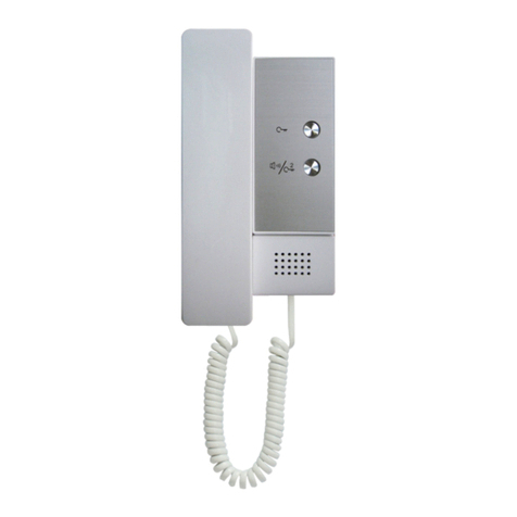
SeaCom SC211 User guide

SeaCom System Manual
The manual for the SeaCom 2100 maritime intercom system
• Covers SeaCom 2100 telephone system
• Covers SC211, SC220, SC411 and SC421 stations
• Covers the Windows based configuration tool
• Valid for the SeaCom 1 '' systems as well
Søren Frichs Vej 38 DK-8230 Aabyhøj Denmark www.seacom.dk te ephone: +45 86 296 297

SeaCom System Manual Page 4 of 139
SeaCom 10-600-0010_0405 TMN100510CJ01_0405

SeaCom System Manual Page 5 of 139
SeaCom 10-600-0010_0405 TMN100510CJ01_0405

SeaCom System Manual Page 6 of 139
SeaCom 10-600-0010_0405 TMN100510CJ01_0405

SeaCom System Manual Page 7 of 139
SeaCom 10-600-0010_0405 TMN100510CJ01_0405

SeaCom System Manual Page 8 of 139
SeaCom 10-600-0010_0405 TMN100510CJ01_0405
CONTENT
1. INTRODUCTION .................................................. 14
1.1 PURPOSE OF THIS MANUAL ..................... 14
1.2 LIABILITY ............................................... 14
1.3 REVISIONS ............................................. 14
2. IMPORTANT SAFETY NOTES .......................... 15
3. SYSTEM DESCRIPTION ..................................... 16
3.1 PURPOSE OF THE SYSTEM ...................... 16
3.2 OPERATIONAL FEATURES ....................... 16
3 2 1 ON BOARD COMMUNICATION 16
3 2 2 DISTRIBUTE SATCOM 16
3 2 3 TALK BACK 16
3 2 4 CONFERENCE 16
3 2 5 PA FUNCTIONS 16
3 2 6 TIME DISTRIB AND WAKE UP 16
3 2 7 CALL DATA MANAGEMENT 16
3.3 MAIN SYSTEM COMPONENTS .................. 17
3 3 1 EXCHANGE 17
3 3 2 EXCHANGE CIRCUIT BOARDS 17
3 3 3 17
3 3 4 AEXT16 17
3 3 5 COMMUNICATION STATIONS 18
3 3 6 TELEPHONES 19
3 3 7 POWER SUPPLY 19
3.4 TYPICAL INSTALLATION EXAMPLE ........... 20
3.5 ................................................................. 20
4. DESIGNING A SYSTEM ..................................... 21
4.1 ANALYZING............................................ 21
4 1 1 COUNTING LOCATIONS 21
4 1 2 ENVIRONMENT 21
4 1 3 TYPE OF COMMUNICATION 21
4 1 4 SATELLITE LINES 21
4 1 5 AUDIO I/O 21
4.2 SELECTING TELEPHONES/STATIONS ........ 21
4 2 1 ANALOGUE TELEPHONES 21
4 2 2 SEACOM 411 21
4 2 3 SEACOM 211 22
4 2 4 SEACOM 421 22
4 2 5 SEACOM 220 22
4.3 SELECTING THE EXCHANGE SYSTEM ....... 22
4 3 1 CHOOSING AEXTXX-XX 22
4 3 2 TRUNK AND AUDIO I/O (FIOX 22
4 3 3 CABLE TERMINATIONS (CTU) 22
4 3 4 POWER DISTRIBUTION (PDU) 22
4 3 5 CONCLUSION 22
4.4 ASSEMBLING THE EXCHANGE ................. 23
4 4 1 CARD GUIDES 23
4 4 2 INSERTING BOARDS 23
4 4 2 1 Board positions 23
4 4 3 MOUNTING CTU’S 23
4 4 4 MOUNTING THE RIBBON CABLES 23
4.5 POWER.................................................. 23
4 5 1 MOUNTING PDU’S 23
4 5 2 FUSING 24
4 5 3 POWER CONSUMPTION - EXCHANGE 24
4 5 4 POWER CONSUMPTION - STATIONS 24
4.6 THE ASSEMBLED EXCHANGE SYSTEM ...... 24
4.7 FIRST TIME POWER UP ............................ 25
4 7 1 BURN-IN 25
5. INSTALLATION ................................................... 26
5.1 PRE-INSTALLATION CONSIDERATIONS ..... 26
5.2 CABLES................................................. 26
5.3 WIRING DIAGRAM ................................... 26
5.4 MOUNTING THE EXCHANGE ..................... 26
5.5 MOUNTING THE STATIONS....................... 27
5 5 1 BULKHEAD 27
5 5 2 FLUSH MOUNT 27
5.6 POWER CONSIDERATIONS ...................... 27
5 6 1 GALVANIC CONNECTION TO BATTERY 27
5 6 2 FUSES 28
5 6 3 COMMON POWER SUPPLY ONLY 28
5.7 SHIELDING AND PROTECTIVE EARTH ....... 28
5 7 1 AT THE EXCHANGE 28
5 7 2 WIRING AND JUNCTION BOXES 28
5 7 3 AT THE STATIONS 28
6. COMMISSIONING ................................................ 30
6.1 FIRST TIME POWER ON ........................... 30
6.2 SYSTEM PROGRAMMING ......................... 30
6.3 EQUIPMENT TYPE ................................... 30
6.4 NUMBER PLAN ....................................... 30
6.5 ACCESS PRIVILEGES .............................. 31
6.6 SYSTEM CALL NUMBERS ......................... 31
6.7 TESTING ................................................ 31
6 7 1 EXTENSIONS 31
6 7 2 STATIONS 31
6 7 2 1 SeaCom 211 the talk-back stations31
6 7 2 2 SeaCom 220 industrial telephone 31
6 7 2 3 SeaCom 421 and SeaCom 411 31
6 7 3 TRUNK LINES 31
6 7 4 I/O 31
6 7 5 TESTING SYSTEM CALL NUMBERS 31
6 7 6 ACCESS PRIVILEGES 32
6.8 END USER MANUAL ................................ 32
7. OPERATION ........................................................ 33

SeaCom System Manual Page 9 of 139
SeaCom 10-600-0010_0405 TMN100510CJ01_0405
7.1 MAKING AND TRANSFERRING A CALL ...... 33
7.2 RINGING SIGNALS .................................. 33
7.3 TONE SIGNALS ....................................... 33
7.4 PRIORITY CALL ...................................... 33
7.5 DIRECT IN .............................................. 33
7.6 DIRECT IN TO RINGING GROUP ................ 33
7.7 SETTING SYSTEM TIME ........................... 34
7.8 ORDERING A WAKE-UP CALL ................. 34
7.9 RINGING GROUPS ................................... 34
7.10 USING THE CALL DATA MANAGER ......... 34
7.11 PAGING CALLS..................................... 34
7.12 PA GROUP CONFERENCE..................... 34
7.13 ALARM CALLS ..................................... 34
7.14 CALL PICKUP ....................................... 35
7.15 MUSIC WHEN FREE ............................... 35
7.16 TALK-BACK COMMAND CALLS .............. 35
7.17 REVERSE TALK-BACK .......................... 35
7.18 CONFERENCE ...................................... 35
7.19 DO NOT DISTURB ................................. 35
7.20 DAY-MODE NIGHT-MODE ....................... 36
7.21 CALLS VIA TRUNK LINES ....................... 36
8. MAINTENANCE ................................................... 37
8.1 HEADSETS ............................................. 37
8.2 BATTERIES OF ANALOGUE TELEPHONES . 37
9. SEACOM 2100 .................................................... 38
9.1 SPECIFICATION ...................................... 38
9.2 EXPLODED VIEW .................................... 38
9.3 MECHANICAL OUTLINE ........................... 39
9.4 THE SYSTEM INSIDE................................ 40
9 4 1 BOARD MAGAZINE 40
9 4 2 CABLE TERMINATION AREA 40
9 4 3 POWER INPUT MODULE - PIM 40
9 4 4 J1 POWER INPUT 40
9 4 5 J3 POWER OUTPUT 40
9 4 6 FUSES 40
9 4 7 INDICATORS 40
10. CIRCUIT BOARDS. ........................................... 41
10.1 PSU POWER SUPPLY UNIT .................... 41
10 1 1 TECHNICAL DATA 41
10 1 2 ON/OFF SWITCH 41
10 1 3 INDICATORS 41
10 1 4 ALARM RELAY 41
10 1 5 FAN DRIVE 42
10 1 6 INPUT POWER SUPERVISION 42
10 1 7 TEMPERATURE PROTECTION 42
10 1 8 LAYOUT 43
10.2 CP2 CENTRAL PROCESSOR .................. 44
10 2 1 TECHNICAL DATA 44
10 2 2 SERIAL PORT 44
10 2 3 ADVANTEC SOM 4455 44
10 2 4 INDICATORS 45
10 2 5 RESET BUTTON 45
10 2 6 LAYOUT 45
10.3 F O2 MASTER AND SLAVE .................... 46
10 3 1 FEATURES OF THE MASTER 46
10 3 2 TECHNICAL DATA 46
10 3 3 CONNECTOR 46
10 3 4 LINE ACTIVITY INDICATORS 47
10 3 5 SELECTING TRUNK OR AUDIO I/O 47
10 3 6 TRUNK LINE CIRCUITS 47
10 3 7 AUDIO I/O CIRCUITS 47
10 3 8 LAYOUT 48
10.4 AEXT8 ............................................... 49
10 4 1 TECHNICAL DATA 49
10 4 2 FRONT CONNECTOR 49
10 4 3 LINE ACTIVITY INDICATORS 49
10 4 4 LAYOUT 50
10.5 THE AEXT16 ...................................... 51
10 5 1 INDICATORS 51
10 5 2 JUMPERS 51
10 5 3 BOARD LAYOUT 52
10.6 THE F O4 ............................................ 53
10 6 1 INDICATORS 53
10 6 2 FIO4 CONNECTORS 53
10 6 3 TRUNK LINES 54
10 6 4 AUDIO I/O 54
10 6 5 RELAYS 54
10 6 6 DIGITAL INPUT 54
10 6 7 ZONE RELAY DRIVE 54
10 6 8 JUMPERS 54
10 6 9 BOARD LAYOUT 55
10.7 CTU2 ................................................. 56
10 7 1 TECHNICAL DATA 56
10 7 2 USING THE CTU2 56
10 7 3 MAPPING 56
10 7 4 LAYOUT 56
10.8 CTU24 ............................................... 57
10 8 1 TECHNICAL DATA 57
10 8 2 USING THE CTU24 57
10 8 3 MAPPING 57
10 8 4 BOARD LAYOUT 57
10.9 PDU ................................................... 58
10 9 1 TECHNICAL DATA 58
10 9 2 USING THE PDU 58
10 9 3 POWER DESIGN 58
10 9 4 LAYOUT 59
10.10 P M .................................................. 60
10 10 1 TECHNICAL DATA 60
10 10 2 J1 POWER INPUT 60
10 10 3 J3 POWER OUTPUT 60
10 10 4 FUSES 60
10 10 5 INDICATORS 61
10 10 6 ALARM RELAY 61
10 10 7 LAYOUT 61
10 10 8 AC CONNECTORS 61
10.11 BACKPLANE ...................................... 62
10 11 1 TECHNICAL DATA 62
10 11 2 USING THE BACKPLANE 62
10 11 3 J22 – THE POWER CONNECTOR 62
10 11 4 LAYOUT 63

SeaCom System Manual Page 10 of 139
SeaCom 10-600-0010_0405 TMN100510CJ01_0405
11. STATIONS ......................................................... 64
11.1 MECHANICS AND MOUNTING ................. 64
11 1 1 THE KEYBOARD 64
11 1 2 INS AND OUTS 64
11 1 3 GORE VENT 64
11 1 4 MOUNTING BRACKETS 65
11 1 5 CABLES AND SHIELDING 65
11 1 6 THE SILICA GEL BAG 65
11 1 7 THE HANDSET 66
11 1 7 1 Mounting the handset 66
11 1 8 HEADSET 67
11 1 8 1 Mounting headset connector 67
11 1 9 EXPOSED EQUIPMENT 67
11 1 9 1 Mounting the door 68
11 1 10 FEATURES OVERVIEW 69
11 1 11 HANDSET MECHANICAL OUTLINE 70
11 1 12 CROSS RAIL DRAWING 70
11.2 SEACOM 211 ...................................... 71
11 2 1 DESCRIPTION 71
11 2 2 SPECIFICATION 71
11 2 3 INSIDE 71
11 2 4 ELECTRICAL CONNECTIONS 72
11 2 5 JUMPER FIELD 72
11 2 6 VOLUME SETTINGS 72
11 2 7 OPERATING 73
11 2 7 1 Making calls 73
11 2 7 2 Receiving calls 73
11 2 7 3 Conducting calls 73
11 2 7 4 Terminating a call 73
11 2 7 5 Receiving paging calls 73
11 2 7 6 Command group (talk-back) 73
11 2 8 MECHANICAL OUTLINE 74
11 2 9 PCB LAYOUT 75
11 2 10 SCHEMATIC 76
11.3 SEACOM 220 ...................................... 77
11 3 1 DESCRIPTION 77
11 3 2 SPECIFICATION 77
11 3 3 ON THE FRONT 77
11 3 4 INSIDE 78
11 3 5 ELECTRICAL CONNECTIONS 78
11 3 6 PROGRAMMING 78
11 3 7 OPERATING 79
11 3 7 1 Handset calls 79
11 3 7 2 Headset calls 79
11 3 7 3 PTT mode 79
11 3 7 4 Receiving calls 79
11 3 7 5 Timed termination 79
11 3 7 6 Busy tone termination 79
11 3 7 7 Call transfer 79
11 3 8 MECHANICAL OUTLINE 80
11 3 9 PCB LAYOUT 81
11 3 10 SCHEMATIC 82
11.4 SEACOM 411 / SEACOM 421 ............... 83
11 4 1 DESCRIPTION 83
11 4 2 SPECIFICATIONS 83
11 4 3 ON THE FRONT 84
11 4 4 INSIDE 84
11 4 5 ELECTRICAL CONNECTIONS 84
11 4 6 J2 - RS422 INTERFACE 84
11 4 7 KEYS 85
11 4 7 1 F1 to F3 85
11 4 7 2 Up down keys 85
11 4 7 3 M key 85
11 4 7 4 Speaker key (hands free) 85
11 4 7 5 PTT key 85
11 4 7 6 R key (transfer) 85
11 4 8 DISPLAY 85
11 4 8 1 Status field 85
11 4 9 CALL INDICATOR 85
11 4 10 BACKLIGHT CONTROL 85
11 4 11 MOUNTING THE SEACOM 411 85
11 4 12 OPERATING 87
11 4 12 1 Modes of conversation 87
11 4 12 2 Dialing 87
11 4 12 2 1 Speed dial 87
11 4 12 2 2 Memory dial 87
11 4 12 2 3 Last number re-dial 87
11 4 12 2 4 Call lists and re-dial 87
11 4 12 3 How to answer a call 87
11 4 12 4 Direct in calls 87
11 4 12 5 Voice activated answering 87
11 4 12 6 Terminating a call 87
11 4 12 7 Switching mode of conversation 87
11 4 12 8 Switching between PTT and full duplex
87
11 4 12 9 PA call and PA volume 88
11 4 13 THE MENU SYSTEM 89
11 4 13 1 Navigating in the menu 89
11 4 13 2 The menu – overview 89
11 4 13 2 1 Speaker volume 89
11 4 13 2 2 Backlight 89
11 4 13 2 3 Ringer volume 89
11 4 13 2 4 P A volume 89
11 4 13 2 5 Bell signal 89
11 4 13 2 6 Calls out 89
11 4 13 2 7 Call in 89
11 4 13 2 8 Auto answer 89
11 4 13 2 9 Auto busy 89
11 4 13 2 10 Direct in 90
11 4 13 2 11 Hands free 90
11 4 13 2 12 External speaker 90
11 4 13 2 13 Date & time 90
11 4 13 2 14 Speed dial 90
11 4 13 2 15 Memory dial 90
11 4 13 2 16 Dial signal 90
11 4 13 2 17 Loop dial type 90
11 4 13 2 18 Remote PTT 90
11 4 13 2 19 Remote Hook Switch 90
11 4 13 2 20 Local Extern Microphone 90
11 4 13 2 21 Headset microphone type 90
11 4 13 2 22 Headset VOX 91
11 4 13 2 23 Local microphone gain 91
11 4 13 2 24 Handset microphone gain 91
11 4 13 2 25 Headset microphone gain 91
11 4 13 2 26 External microphone gain 91
11 4 13 2 27 Relay mode 91
11 4 13 2 28 Relay hold off 91
11 4 13 2 29 Contrast 91
11 4 13 2 30 F1 mode 91

SeaCom System Manual Page 11 of 139
SeaCom 10-600-0010_0405 TMN100510CJ01_0405
11 4 13 2 31 Voice hook off 91
11 4 14 MECHANICAL OUTLINE 92
11 4 15 PCB LAYOUT 93
11 4 16 SCHEMATIC 94
12. SYSTEM PROGRAMMING ............................... 97
12.1 GETTING ACCESS TO THE SYSTEM ........ 97
12 1 1 USB ACCESS TO THE CONFIG FILE 97
12 1 2 USB BACKUP 98
12 1 3 NETWORK ACCESS 98
12 1 3 1 Setting a fixed IP address 98
12 1 3 2 Using dynamic IP address 99
12 1 3 3 Mapping the system disk 99
12.2 GENERAL CONCEPTS ......................... 101
12 2 1 PASSWORD 101
12 2 2 CALL NUMBERS / DESCRIPTIONS 101
12 2 3 SERVICE GROUPS 101
12 2 3 1 The editor 101
12 2 4 SYSTEM CALL NUMBERS 102
12.3 THE MXCONFIG.EXE APPLICATION ...... 103
12 3 1 THE FILES MENU 103
12 3 1 1 Open 103
12 3 1 2 Save 103
12 3 1 3 Save As 103
12 3 1 4 Export "_new" file 103
12 3 1 5 Exit 103
12 3 2 THE EDIT MENU 103
12 3 2 1 Add system call 103
12 3 2 2 The Directory menu 103
12 3 2 3 Service groups menu 103
12 3 3 19'' RACK EDITOR 103
12 3 4 CLASSIC EDITOR 104
12 3 4 1 Selecting a new board type 104
12 3 4 1 1 AEXT8 board 104
12 3 4 1 2 FIO2 board 104
12 3 4 1 3 FIO2 Master 104
12 3 4 1 4 AEXT16 board 105
12 3 4 1 5 FIO4 board 105
12 3 5 THE TOOLS MENU 105
12 3 5 1 Preferences 105
12 3 5 1 1 Installation identifier 105
12 3 5 1 2 Serial number 105
12 3 5 1 3 Last extension number 105
12 3 5 1 4 COM Port 105
12 3 5 1 5 Error log level 105
12 3 5 1 6 CP watchdog enable 105
12 3 5 1 7 Alarm when extension error 105
12 3 5 1 8 Use PCCP V2 105
12 3 5 1 9 This is a mode file 106
12 3 5 1 10 Real time clock 106
12 3 5 1 11 Day mode / night mode 106
12 3 5 2 Renumber extensions 106
12 3 5 2 1 Change all extensions to SC325
106
12 3 5 2 2 Clear file 106
12 3 6 THE ABOUT MENU 106
12.4 THE TELEPHONE DIRECTORY .............. 106
12 4 1 HEADER FIELD 106
12 4 2 THE DIRECTORY GRID 106
12 4 3 POP UP MENU 107
12 4 3 1 Properties menu 107
12 4 3 2 Service group menu 107
12 4 3 3 Add system call number 107
12 4 3 4 Delete system call 107
12 4 3 5 Sorting the telephone directory 107
12 4 3 6 Sort by call number 107
12 4 3 7 Sort by description 107
12 4 3 8 Physical order 107
12 4 3 9 Show includes in mode file changes 107
12 4 3 10 Filtering the telephone directory108
12 4 3 11 Show directory filter 108
12 4 3 12 Will connect from 108
12 4 3 13 Can connect to 108
12 4 3 14 Print 108
12 4 3 15 Export to ASCII file 108
12 4 3 16 Copy extension settings 108
12.5 PROPERTIES OF INDIVIDUALS .............. 110
12 5 1 BASIC ANALOGUE EXTENSION 110
12 5 1 1 Call number / Description 110
12 5 1 2 Equipment type 110
12 5 1 3 Display 110
12 5 1 4 Dial on hook off 110
12 5 1 5 Loop disconnect dial 110
12 5 1 6 No hook detect while ringing 110
12 5 2 SEACOM 325 110
12 5 2 1 Call number / Description 110
12 5 2 2 Display 111
12 5 2 3 Dial on hook off 111
12 5 2 4 No direct-in 111
12 5 3 SEACOM 211 TALK-BACK STATION 111
12 5 3 1 Call number / Description 111
12 5 3 2 Dial on PTT and buttons pressed111
12 5 3 3 No hook detect while ringing 111
12 5 4 SEACOM 411 AND 421 STATIONS 111
12 5 4 1 Call number / Description 111
12 5 4 2 FSK Mode 111
12 5 4 3 Dial on hook off 111
12 5 5 ANALOGUE TRUNK 112
12 5 5 1 Call number / Description 112
12 5 5 2 Trunk group 112
12 5 5 3 Incoming calls handling 112
12 5 5 3 1 Incoming mode 112
12 5 5 3 2 Hook off when routing 112
12 5 5 3 3 Delay before handling incoming call 112
12 5 5 3 4 Incoming routing list 112
12 5 5 4 Outgoing calls 112
12 5 5 4 1 Prefix dialing 113
12 5 5 4 2 B-answer mode 113
12 5 5 4 3 Release on no B number 113
12 5 5 5 Advanced options 113
12 5 5 5 1 Line feed detector 113
12 5 5 5 2 Call progress tone detector 114
12 5 5 5 3 Call DTMF tone lengths 114
12 5 6 AUDIO IN/OUT 114
12 5 6 1 Call number / Description 114
12 5 6 2 Incoming calls handling 114
12 5 6 2 1 Ear input control 114
12 5 6 2 2 Mouth relay control 114

SeaCom System Manual Page 12 of 139
SeaCom 10-600-0010_0405 TMN100510CJ01_0405
12 5 6 2 3 Audio enable 114
12 5 6 2 4 Connection time limit 114
12 5 6 2 5 Routing list 115
12 5 6 3 Outgoing calls 115
12 5 6 3 1 Mouth relay control 115
12 5 6 3 2 Ear input control 115
12 5 6 3 3 Enable and multiple listeners 115
12 5 6 3 4 Connection time limit 115
12 5 7 PRIORITY CALL 115
12 5 7 1 Call number / Description 115
12 5 7 2 Enables 115
12 5 8 SHORT NUMBER DIALER 116
12 5 8 1 Call number / Description 116
12 5 8 2 Start dialing 116
12 5 8 3 Collect and append 116
12 5 8 4 Terminate by dialing 116
12 5 9 NEW DIAL TONE 116
12 5 9 1 Call number / Description 116
12 5 10 NUMBER ALIAS 116
12 5 10 1 Call number / Description 116
12 5 10 2 Call number list 116
12 5 11 WAKE-UP CALL ORDERING 117
12 5 11 1 Call number / Description 117
12 5 11 2 Mode 117
12 5 12 USER ACCOUNT AND PIN-CODE
CHECKER 117
12 5 12 1 Call number / Description 117
12 5 12 2 User data format 117
12 5 12 3 Call number list 117
12 5 13 SET DATE AND TIME SYSTEM 118
12 5 13 1 Call number / Description 118
12 5 13 2 Collect and set 118
12 5 14 RINGING GROUP 118
12 5 14 1 Call number / Description 118
12 5 14 2 Call number list 118
12 5 14 3 Connect busy members 118
12 5 15 CALL PICKUP 118
12 5 15 1 Call number / Description 119
12 5 15 2 Pickup mode 119
12 5 16 PAGING CALL 119
12 5 16 1 Call number / Description 119
12 5 16 2 Paged service groups 119
12 5 16 3 Priority 119
12 5 16 4 Attention sound (Gong) 119
12 5 16 5 Allow answering 119
12 5 16 6 Close PA call on answering 119
12 5 17 SEMI-DUPLEX CONFERENCE 120
12 5 17 1 Call number / Description 120
12 5 17 2 Conference master 120
12 5 17 3 Members 120
12 5 17 4 Mode 120
12 5 18 ALARM DISTRIBUTION CALL 120
12 5 18 1 Call number / Description 121
12 5 18 2 Alarmed service groups 121
12 5 18 3 Alarm type selection 121
12 5 18 4 Activating alarm by relay 121
12 5 18 5 Priority 121
12 5 19 MODE SELECT SYSTEM CALL 121
12 5 19 1 Call number / Description 122
12 5 19 2 Configuration file selected 122
12 5 20 ‘DO NOT DISTURB’ SYSTEM CALL 122
12 5 20 1 Call number / Description 122
12 5 20 2 Action when calling 122
12 5 20 3 Time-out 122
12 5 20 4 Select disturbers 122
12 5 21 MUSIC WHEN FREE 122
12 5 21 1 Call number / Description 122
12 5 21 2 Settings 122
12 5 22 DIRECT-IN REQUEST 123
12 5 22 1 Call number / Description 123
12 5 22 2 Action when calling 123
12 5 23 DAY MODE / NIGHT MODE 123
12 5 23 1 Action when calling 123
12 5 24 CONFERENCE 123
12 5 24 1 Call number / Description 123
12 5 24 2 Members 123
12 5 24 3 Answer Modes 124
12 5 24 4 Audio processing 124
13. CALL DATA MANAGER .................................. 125
13.1 GENERAL .......................................... 125
13.2 THE CLIENT/SERVER CONCEPT ........... 125
13.3 NSTALLING THE CDM ........................ 125
13 3 1 ACTIVATING THE CDM ENGINE 125
13 3 2 INSTALLING THE CLIENT SOFTWARE 125
13 3 3 ACCESS CALL NUMBER 126
13.4 BACKUP ............................................ 126
13.5 FIREWALL ......................................... 126
13.6 GENERAL CONCEPTS ......................... 126
13 6 1 USERS 126
13 6 2 ACCOUNT NUMBER 126
13 6 3 PIN CODE 126
13 6 4 PROCESSING OF A CALL 126
13 6 5 CALL DATA RECORDS 126
13 6 6 MARKING CALL DATA AS INVOICED 126
13.7 THE CDM SOFTWARE ........................ 127
13 7 1 THE USER EDITOR 127
13 7 1 1 Users data editor 127
13 7 1 1 1 User data 127
13 7 1 1 2 Account number 127
13 7 1 1 3 Account 128
13 7 1 1 4 Calls 128
13 7 1 1 5 Non-invoiced 128
13 7 1 1 6 The summary window 128
13 7 1 2 The users menu 128
13 7 1 2 1 Add user 128
13 7 1 2 2 Deleting users 128
13 7 1 2 3 Delete all users 128
13 7 1 2 4 Reset PIN 128
13 7 1 2 5 Enter PIN 128
13 7 1 2 6 Previewing and printing of user list 128
13 7 1 2 7 Printing invoices of all users 129
13 7 1 2 8 Sorting user data 129
13 7 1 2 9 Export user data 129
13 7 1 2 10 Import user data 129
13 7 2 THE CALL DATA VIEWER 129
13 7 2 1 Time of call 129
13 7 2 2 Acc 129

SeaCom System Manual Page 13 of 139
SeaCom 10-600-0010_0405 TMN100510CJ01_0405
13 7 2 3 Called number 129
13 7 2 4 Duration 130
13 7 2 5 Charge 130
13 7 2 6 Group 130
13 7 2 7 Extension 130
13 7 2 8 Trunk 130
13 7 2 9 Error message 130
13 7 2 10 Invoiced 130
13 7 2 11 Selecting the users data 130
13 7 2 12 The filter window 130
13 7 2 12 1 User name filtering 130
13 7 2 12 2 Account filtering 130
13 7 2 12 3 Selecting all users 130
13 7 2 12 4 Invoiced filtering 130
13 7 2 13 The summary window 130
13 7 2 13 1 Selected user 130
13 7 2 13 2 Totals display 130
13 7 2 14 Operating the call data 130
13 7 2 14 1 Deleting call data 130
13 7 2 14 2 Previewing and printing of call
data 131
13 7 3 CHARGE EDITOR 131
13 7 3 1 Trunk group 131
13 7 3 2 Digits mask 131
13 7 3 3 Free time 131
13 7 3 4 Base charge and Charge pr Minute132
13 7 4 SHORT NUMBER EDITOR 132
14. CP AND ITS APPLICATIONS .......................... 133
14.1 CONTENTS OF THE SYSTEM FOLDER .... 133
14.2 SYSTEM INSTALLATION BACKUP ......... 133
14.3 VNCVIEWER.EXE ................................ 134
14.4 MXPROCESS ..................................... 134
14.5 NMEA_TIMERECEIVER...................... 134
14.6 USB UPDATE AGENT .......................... 135
15. LIST OF SPARE PARTS ................................. 136
16. TROUBLE SHOOTING .................................... 137
16.1 PROBLEMS WITH STATIONS ................ 137
16.2 PROBLEMS WITH TRUNK LINES............ 137
16.3 EXCHANGE ........................................ 137
16 3 1 STEP BY STEP START UP 138

SeaCom System Manual Page 14 of 139
SeaCom 10-600-0010_0405 TMN100510CJ01_0405
1. Introduction
Thank You for choosing SeaCom as Your
supplier of wired on board communication
This manual will introduce You to our maritime
communication system, and take You through
all parts of the process from evaluating the
needs for communication through designing
and building a system towards commissioning
and delivery to the end user
As well as being a reference for finding
technical data, we have added a handful of
chapters giving good to know information, and
explaining good installation praxis which have
been proven to work in real life
We hope You will enjoy working with our
system
1.1 Purpose of this manual
This manual is a generic manual meant for
salesmen and installers It cannot be left alone
as an end user manual
It is the responsibility of the installer to create
an end user manual, based on the numerous
choices made during the design and
architecture of a specific installation
1.2 Liability
The information contained in the manual is
distributed on an “As is” basis, without
warranty While every effort has been taken in
the preparation of this manual, SeaCom shall
not be held liable with respect to any liability,
loss, or damage caused by the instructions
contained in this manual The information
contained in this manual is subject to change
without notice
1.3 Revisions
This manual addresses only systems updated
in all aspects to the latest versions If You
have old hardware and software, some of the
features described might not be implemented

SeaCom System Manual Page 15 of 139
SeaCom 10-600-0010_0405 TMN100510CJ01_0405
2. IMPORTANT SAFETY NOTES
• Telephone equipment makes use of
DC voltages of 48V and AC voltages
of 80V It is the responsibility of the
installer to make sure that the
electrical parts of our system is
properly covered, and that the PE
(Protective Earth) is always taken
back from all stations to the exchange
system and properly wired to ship hull
• Only authorized personnel should
open any of our boxes
• Always power the system off before
handling
• The installer is reliable for proper
fusing the system, and for designing
the wiring and power supply capacity
in a way that ensures that fuses blow
first if a short circuit should happen
• NEVER connect 230V AC to ANY
terminal of this system It is powered
by 24V DC only
• Relays of this product is designed to
carry max 50V, 1A Make sure that
the wires are fused by max 1A
NEVER connect 230V AC to any relay
terminals
• NEVER leave the exchange without
the cover put back on
• The SeaCom 2100 is enclosed by a
heavy steel box Handle these with
care and mount the properly fastened,
so they do not drop of their brackets
• Make sure that the exchange unit is
mounted according to the instructions
on a vertical
bulkhead in order to assure proper
ventilation of the system

SeaCom System Manual Page 16 of 139
SeaCom 10-600-0010_0405 TMN100510CJ01_0405
3. System description
This chapter is meant for first time users of the
SeaCom 2100 communication system
It will give an overview of what You can do
with the system, the features You will find, and
overview of the system components involved
3.1 Purpose of the system
The purpose of the SeaCom 2100 maritime
communication system is to give the seamen
easy and reliable on board communication
between all essential places on board a ship,
as well as giving the possibility of making
telephone calls to and from the ship, via
satellite communication terminals
3.2 Operational features
The list below gives an overview of the
features to be found:
• On board communication
• Distribute satellite communication
• Talk back command
• Conference calls
• Public Address (PA)
• Time distribution
• Wake up calls
• Call Data Management
3.2.1 On board communication
On board conversations between bridge,
ECR, cabins, offices, work shop, deck etc
All locations, no matter if it is dry, wet, noisy or
dirty, can be covered by either an plain old
analogue telephone or one of our
communication stations with handset, headset
or loudhailer
3.2.2 Distribute satcom
Calls from the ship to shore can be conducted
from all places on board The seaman can
have his privacy by calling the family from his
cabin for example
Calls from shore to ship can be distributed to
all locations on board, typically to bridge,
captains cabin or to ship office You don’t
have to be on the bridge to answer Your
incoming satellite calls
3.2.3 Talk back
Our communication station SeaCom 211 can
be used to implement the classical talk-back
functions A call from bridge to mooring
stations for example, can be set up from
bridge, without hands-on on deck Groups of
stations can be addressed simultaneously
when performing a command group
conference call
3.2. Conference
The system allows for conference calls with
one initiator and up to 10 participants
Users can set up a fixed conference, or the
conference can be dynamic created, left and
joined
3.2.5 PA functions
The SeaCom communication system can
distribute public address (acoustic paging) to
all stations with loudspeakers
The system gives possibility of defining groups
with priority levels The system can be set up
to send a gong signal preceding the spoken
message
PA calls are initiated from telephones and
communication stations, and does not require
special control stations with goose neck
microphones
3.2.6 Time distrib and wake up
Using telephones with display gives the
possibility for displaying the ships clock on the
telephones The time displayed can be set
manually by a simple telephone call, or the
SeaCom communication system can receive
the time from a central clock system using
serial NMEA communication
Based on the system time, wake up calls can
be ordered from any telephone connected to
the system
3.2.7 Call Data Management
A ship owner that wants to register calls made
via the satellite equipment connected can
make use of our Call Data Management
system
The seamen are given accounts and PIN
codes which are used to open the access to
the satellite lines When conversations are
conducted, call data records are stored on the
system disk Based on these stored data, the
responsible officer can print invoices covering
the telephone calls made

SeaCom System Manual Page 17 of 139
SeaCom 10-600-0010_0405 TMN100510CJ01_0405
3.3 Main system components
A SeaCom installation consist of the following
main components:
• The exchange
• Communication stations
• Telephones
3.3.1 Exchange
This is the central component of the system
All telephone lines are taken out of this box
from its extension line boards, the satellite
lines are connected to its trunk boards, and
this box also distributes power to the
communication stations via the signal cables
SeaCom 2100
Maritime telephone system with up till 256
telephone and communication station
positions
SeaCom 19''
Maritime telephone system with up till 800
telephone and communication station
positions
3.3.2 Exchange circuit boards
In order to build exchanges that suits the
customers needs, a range of circuit boards are
available for inserting into the basic exchange
systems Each board adding features as
needed
AEXT8
A circuit board adding 8 analogue extension
lines
3.3.3
3.3. AEXT16
A circuit board with 8, 16 or 24 lines
F O2
A circuit board adding 2 trunk lines (satellite)
channels to the system
This board can also be reconfigured for other
IO/ purposes such as audio in and out

SeaCom System Manual Page 18 of 139
SeaCom 10-600-0010_0405 TMN100510CJ01_0405
F O4
A circuit board adding 2 or 4 trunk lines
(satellite) channels to the system
This board also holds audio I/O and a lot of
relay functions
CTU2
Cable termination unit Used for terminating
ship cabling into the system
CTU24
Terminating 24 telephone lines
PDU
Power distribution Used for distributing the
24V DC power to stations
3.3.5 Communication stations
The communication stations are advanced
telephones mounted at each location that
need communication Typically locations like
bridge, Engine Control Room and Steering
Gear Room where a simple telephone will not
do
The following communication stations are
available:
SeaCom 211
Simple water tight station with 3 buttons
Typically used for deck stations Also called
the talk-back station

SeaCom System Manual Page 19 of 139
SeaCom 10-600-0010_0405 TMN100510CJ01_0405
SeaCom 411
Full featured flush mount station with display,
backlight and hands-free Used on bridge and
ECR
SeaCom 421
Full featured water tight station with display,
backlight and hands-free Connect handset
and headset Used in engine spaces, and on
deck
SeaCom 220
Water tight and salt mist resistant industrial
telephone with call relay build in Used in
engine spaces and on deck
3.3.6 Telephones
For dry and heated spaces on board SeaCom
recommend our digital telephone TX325 or the
direct-in/PA enabled SC325 telephone
They are digital telephones displaying
date/time, caller number and caller name
They have hands-free operation and can be
either wall mounted or desk top mounted
3.3.7 Power supply
The SeaCom communication system is
powered by 24V DC only Two inputs are
available:
• Main input (from AC/DC source)
• Battery (from ships radio battery)

SeaCom System Manual Page 20 of 139
SeaCom 10-600-0010_0405 TMN100510CJ01_0405
3. Typical installation example
The figure shows an example of how the
SeaCom communication system can be
architectured
3.5

SeaCom System Manual Page 21 of 139
SeaCom 10-600-0010_0405 TMN100510CJ01_0405
4. Designing a system
The intentions of this chapter is to be a guide
to how to approach the task of designing an
on board communication system, how to
choose the right system components, and how
to build the exchange system
It is to be used by the people who makes
quotations to ship yards and ship owners, as
well as the technicians who is actually
assembling the components
.1 Analyzing
All ships have different needs This is what
makes design and installation of on board
communication challenging The SeaCom
maritime communication system is a very
flexible configurable system which allows You
to meet by far the most requirements
In order to architecture a proper system, You
must first collect information about:
• Number of location that need
communication
• The environment to be expected at each
location
• Type of communication to be carried out
at each location
• Number of Satellite lines to be connected
.1.1 Counting locations
The number of locations needing telephones
must be determined This is done in
cooperation with ship architect and owner
The number determines the size of the
exchange system to be chosen
.1.2 Environment
On each location, the expected noise level
must be known, and the location must be
classified as protected or exposed, where
protected areas are locations like cabins,
offices and bridge, whereas exposed will be
areas like engine room, mooring stations or
workshops
.1.3 Type of communication
On each location it must be chosen which kind
of communication is most convenient The
SeaCom maritime communication system
offers the below communication styles:
• Handset conversation
• Hands-free conversations
• PTT mode (push to talk)
• Headset conversation
Each station can offer the seamen one or
more of these styles It is important to select a
style that fits to the needs and which can be
operational in the given environment for the
intended use
.1. Satellite lines
Count how many 2 wire trunk lines will be
needed for connecting satellite communication
equipment
.1.5 Audio I/O
Count how many I/O channels are used for
radio music and output to external amplifier
units etc
.2 Selecting telephones/stations
Based on the analysis, the equipment to be
placed at each location must be selected
The table below shows typical noise levels to
be encountered on ships
Locat on No se level dB
Accommodat on < 60
Br dge 50-60
Eng ne control room 65-75
Eng ne spaces 80-100
Steer ng gear room 100-120
Close to eng ne or generators 100-130
The table shall be used as a guide only to
choose among the numerous possibilities
given by the SeaCom maritime
communication system
The below describes which type of station to
be used in each type of environment
.2.1 Analogue telephones
Plain analogue telephones are to be used in
protected areas only The TX-325, has the
below operating range:
Hands free up to 65 dB noise
Handset conversations up to 75dB of noise
.2.2 SeaCom 11
This station gives the following possibilities in
protected environment:
• Hands free with build in speaker and
microphone up to 75 dB

SeaCom System Manual Page 22 of 139
SeaCom 10-600-0010_0405 TMN100510CJ01_0405
• Hands free with external speaker up to 85
db of ambient noise
• Push to talk conversations with external
speaker up to 100 dB of noise
• Handset conversations up to 85 dB of
noise
• Operation with headset in up to 120 dB of
noise
.2.3 SeaCom 211
The talk back station is a station to be used in
exposed environment with the below
capabilities:
• Push to talk operation up to 100 dB
• Headset operation up to 120 dB of noise
.2. SeaCom 21
This is the most full featured station, to be
used in exposed areas under the below
conditions:
• Hands free with build in speaker and
microphone up to 75 dB
• Hands free with external speaker up to 85
db of ambient noise
• Push to talk conversations with external
speaker up to 100 dB of noise
• Handset conversations up to 85 dB of
noise
• Operation with headset in up to 120 dB of
noise
.2.5 SeaCom 220
This is a plain analogue telephone with
optional handset or headset To be used in
exposed areas
The capability for operation in noisy areas are:
• Handset operation up to 85 dB
background noise
• Headset operation up to 100 dB of noise
.3 Selecting the exchange system
Based on the analysis , the basic exchange
system must be selected, Either the SeaCom
3000 (refer to own manual), the SeaCom
2100, or our 19'' systems
And the circuit boards to be added to this
basic system must be chosen
The choice depends on how many extension
boards and trunk boards that are needed, and
the number of CTU’2 (cable termination units)
and PDU’s (power distribution units) needed
to actually terminate the ship cables for the
purpose
.3.1 Choosing AEXTxx-xx
The total number of extension lines including
lines for the stations SeaCom 411, SeaCom
211 and SeaCom 421 shall be counted
Add 8, 16 or 24 lines AEXTxx-xx cards to
meet the requirement
.3.2 Trunk and audio I/O (FIOx
Next count the number of 2 wire trunk lines
needed for connecting satellite communication
equipments, and the number of audio in/out
needed for connecting music and external
amplifiers to the system
Add the required number of FIO2 or FIO4 to
meet the requirement
.3.3 Cable terminations (CTU)
Now all the AEXT cards and FIO card need
cable termination units The CTU2 terminates
16 telephone lines and 2 trunk lines, whereas
the AEXT24 terminates 24 telephone lines
only
If audio I/O and relay functions of the FIO
cards are in use, add CTU's to support this as
well
.3. Power distribution (PDU)
The number of stations requiring 24V DC
power must be counted These are the
stations SeaCom 411, SeaCom 211and
SeaCom 421 If the number is 4 or less, the
auxillary output of the power input module
(PIM) found internal to the exchange systems
can be used for powering these stations If the
number is 5 or more, a PDU (power
distribution unit) must be added for each 32
stations
.3.5 Conclusion
Finally it must be checked that the number of
cards and CTU's will fit within the chosen
SeaCom system For the SeaCom 2100 and
19'', a maximum of 18 card spaces are
available, one of which must be the CP card
And the maximum number of CTU's and
PDU's are 16
This manual suits for next models
4
Table of contents
