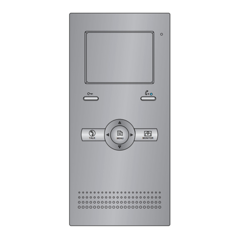
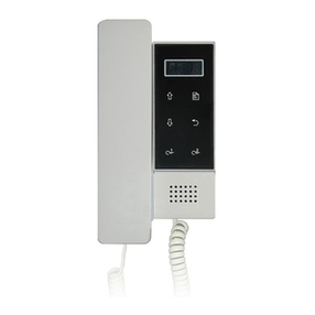
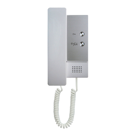
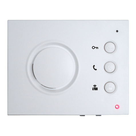
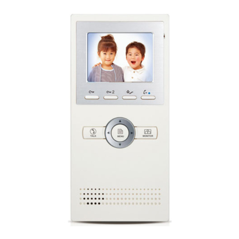
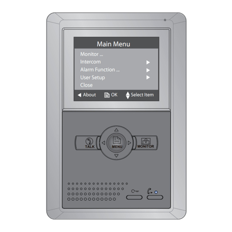
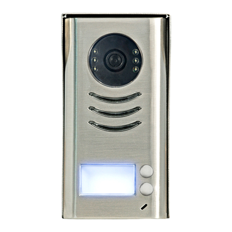
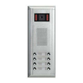
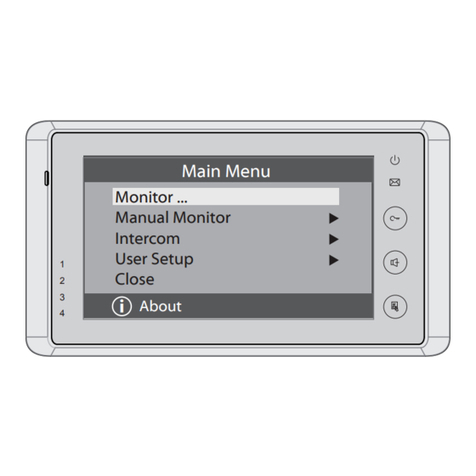
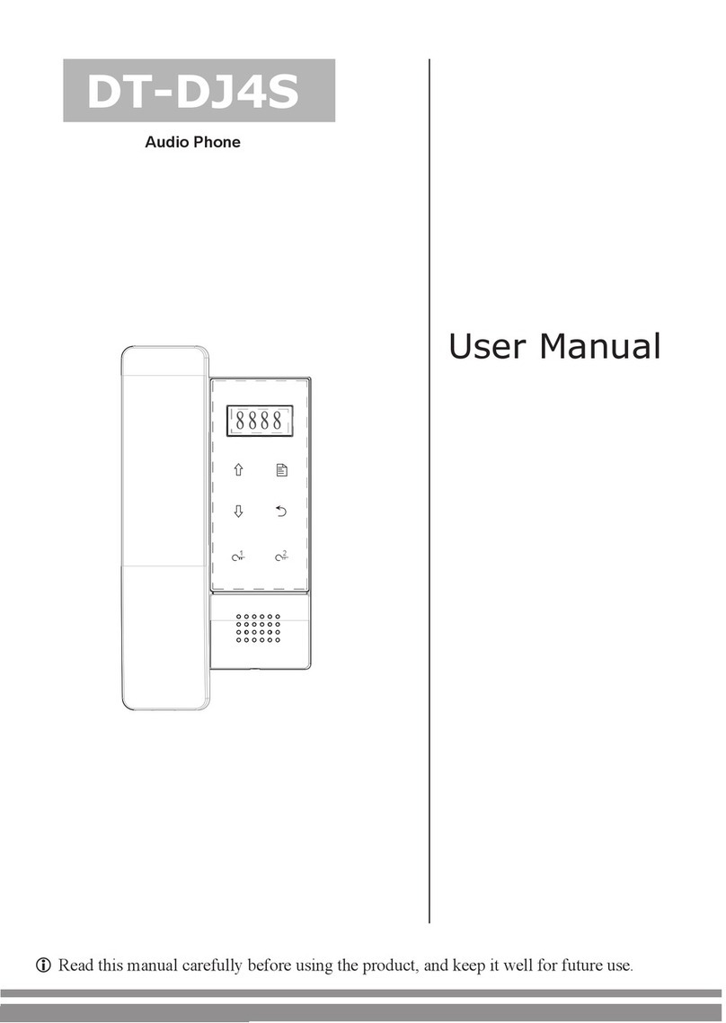
V-Tec DJ4A User manual
Other V-Tec Intercom System manuals
V-Tec
V-Tec DT37MG User manual
V-Tec
V-Tec DT31M User manual
V-Tec
V-Tec Livila VT27 User manual
V-Tec
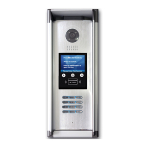
V-Tec DMR11 Series User manual
V-Tec
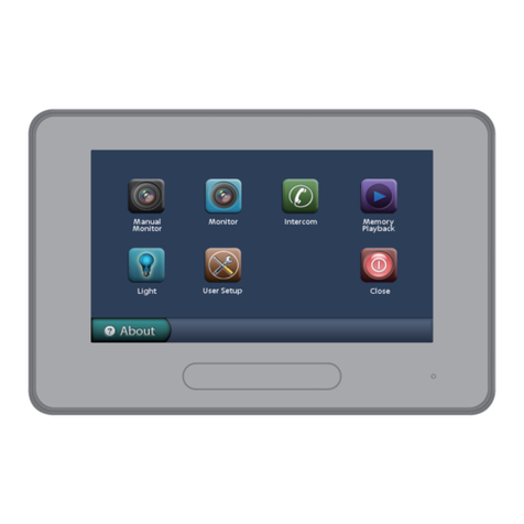
V-Tec 2Easy DMR18s User manual
V-Tec
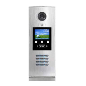
V-Tec 37TD7-V1 User manual
V-Tec
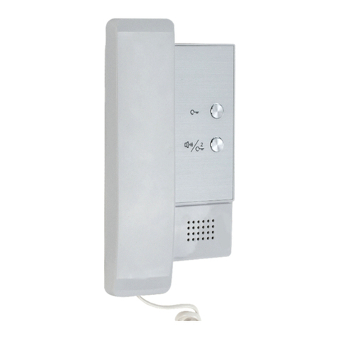
V-Tec DMR18S User manual
V-Tec
V-Tec DT-DJ4A User manual
V-Tec
V-Tec DT24 Series User manual
V-Tec
V-Tec DT596/KP User manual
Popular Intercom System manuals by other brands

MGL Avionics
MGL Avionics V16 manual

SSS Siedle
SSS Siedle BVI 750-0 Installation & programming

urmet domus
urmet domus AIKO 1716/1 quick start guide

urmet domus
urmet domus IPerVoice 1039 Installation

Alpha Communications
Alpha Communications STR QwikBus TT33-2 Installation, programming, and user's manual

Monacor
Monacor ICM-20H instruction manual
