Sealed Air TASKI swingo XP-M User manual

Edition: V1.00/2014
Technical Manual

GTS Technical Manual
28. November 2014 Edition: V1.00/2014 1-1
Copyright © 2014, Diversey Care
technical manual XP_M_R_V1.00IVZ.fm
Index
1Forward
1.1 Target 1
1.2 Technical Training 1
1.3 Technical Manual 1
1.4 Summary 2
2Elementary
2.1 Health & Safety 1
2.2 ESD 1
3 General
3.1 General information 1
3.1.1 Part reference 1
3.1.2 Consumable supplies 1
3.1.3 Direction description 1
3.1.4 Power source 1
3.2 Required material 2
3.2.1 Tools 2
3.2.2 Material 2
4Technicaldata
4.1 Machine range 1
4.2 Technical information 2
4.2.1 Machine profile 2
4.2.2 Technical data 2
4.2.3 Machine speed 3
4.2.4 Dimensions and weights 3
4.2.5 Battery 4
4.2.5.1 Battery compartment 4
4.2.5.2 Battery specifications 5
4.2.6 Charger 6
4.2.7 Brush system 6
4.2.8 Suction power 7
4.2.9 Additional 7
4.3 Accessories & Additional parts 7
4.3.1 Accessories 7
4.3.2 Additional parts 8
5 Mechanical
5.1 Control group 1
5.1.1 Removing of cover 1
5.1.2 Mounting of cover 2
5.1.3 Removing of Electronics hall sensor set 3
5.1.4 Mounting of Electronics hall sensor set 4
5.1.5 Removing of driving speed lever 5
5.1.6 Mounting of driving speed lever 6
5.2 Upper part 7
5.2.1 Removing of vacuum motor 7

GTS Technical Manual
28. November 2014 Edition: V1.00/2014 1-2
Copyright © 2014, Diversey Care
technical manual XP_M_R_V1.00IVZ.fm
5.2.2 Mounting of vacuum motor 8
5.2.3 Removing of tank cover 9
5.2.4 Mounting of tank cover 11
5.2.5 Removing of hose 13
5.2.6 Mounting of hose 14
5.3 Tank 15
5.3.1 Removing of waste water sensor 15
5.3.2 Mounting of waste water sensor 16
5.3.3 Removing of tank set 17
5.3.4 Mounting of tank set 18
5.4 Base 19
5.4.1 Removing of castor wheel 19
5.4.2 Mounting of castor wheel 20
5.4.3 Removing of drive gear 21
5.4.4 Mounting of drive gear 22
5.4.5 Removing of step board 23
5.4.6 Mounting of step board 24
5.5 Fresh water circle 25
5.5.1 Removing of pumps 25
5.5.2 Mounting of pumps 26
5.5.3 Removing of magnetic valve 27
5.5.4 Mounting of magnetic valve 28
5.6 Squeegee lowering mechanism 29
5.6.1 Removing of squeegee linear drive 29
5.6.2 Mounting of squeegee linear drive 30
5.6.3 Removing of swinging arm 31
5.6.4 Mounting of swinging arm 33
5.7 Squeegee 1650/XP/XP-M/XP-R 35
5.7.1 Removing of wire spring 35
5.7.2 Mounting of wire spring 36
5.7.3 Removing of front and back blades 38
5.7.4 Mounting of front and back blades 39
5.8 Tool lowering unit 40
5.8.1 Removing of spring bracket set configured 40
5.8.2 Mounting of spring bracket set configured 42
5.8.3 Removing of brush unit linear drive XP-M 43
5.8.4 Mounting of brush unit linear drive XP-M 44
5.8.5 Removing of brush unit linear drive XP-R 45
5.8.6 Mounting of brush unit linear drive XP-R 46
5.8.7 Removing of tool lowering unit XP-R 47
5.8.8 Mounting of tool lowering unit XP-R 49
5.9 Brush drive 50
5.9.1 Removing of complete brush unit XP-M 50
5.9.2 Mounting of complete brush unit XP-M 52
5.9.3 Removing of complete brush unit XP-R 54
5.9.4 Mounting of complete brush unit XP-R 56
5.9.5 Removing of support with bearing (synchronisation) XP-M 58
5.9.6 Mounting of support with bearing (synchronisation) XP-M 59
5.9.7 Removing of brush belt & brush motor XP-M 60
5.9.8 Mounting of brush belt & brush motor XP-M 61
5.9.9 Removing of eccentric shaft XP-M 62
5.9.10 Mounting of eccentric shaft XP-M 63
5.9.11 Removing of brush belt XP-R 64
5.9.12 Mounting of brush belt XP-R 66
5.9.13 Removing of brush pulley XP-R 68
5.9.14 Mounting of brush pulley XP-R 69
5.9.15 Removing of motor & motor belt XP-R 71
5.9.16 Mounting of motor & motor belt XP-R 72

GTS Technical Manual
28. November 2014 Edition: V1.00/2014 1-3
Copyright © 2014, Diversey Care
technical manual XP_M_R_V1.00IVZ.fm
5.9.17 Removing of intermediate pulley XP-R 73
5.9.18 Mounting of intermediate pulley XP-R 74
6 Electrical
6.1 System architecture 1
6.1.1 General 1
6.2 Dashboard 2
6.2.1 Removing of dashboard 2
6.2.2 Mounting of dashboard 3
6.2.3 Main functions 4
6.2.4 Dashboard connections 4
6.3 Dashboard service menu 7
6.3.1 Reset service hour counter 7
6.4 Power electronics 10
6.4.1 Removing of power electronics 10
6.4.2 Mounting of power electronics 11
6.4.3 Main functions 12
6.4.4 Power electronics connections 12
6.5 Charger 16
6.5.1 Removing of charger 16
6.5.2 Mounting of charger 17
6.5.3 Charger connections 18
6.6 Power relay 20
6.6.1 Removing of power relay 20
6.6.2 Mounting of power relay 21
6.7 Hall sensors 22
6.7.1 Description 22
6.7.2 Guidance 22
6.7.3 Throttle 23
6.7.4 Brush pressure 23
6.8 Safety concept 24
6.8.1 Concept 24
6.8.2 Electromechanical disconnection (Relay 04/137) 24
6.8.3 Emergency loop 25
6.8.4 SAFETY_OK signal loop 26
6.8.5 Emergency brake 27
6.8.6 Charging batteries with low voltage 27
6.8.7 Internal-/external charger 27
6.9 Schematics 29
6.9.1 Electrical schematics XP-M 29
6.9.2 Electrical schematics XP-R 30
6.10 Battery 31
6.10.1 Battery connection 6V 31
7 Additional information
7.1 Available GTS Newsletter/Instructions 1
8Revision
9Appendix
10 Notes

28. November 2014 Edition: V1.00/2014
Copyright © 2014, Diversey Care
Technical Manual
1 Forward

GTS Technical Manual
28. November 2014 Edition: V1.00/2014 1-1
Copyright © 2014, Diversey Care
01.0 TASKI - foreword_V1.00.fm
1 Foreword
1.1 Target
To serve our customers faster and more efficient it is important to achieve a general
standard of technical know how with our partners in the market.
Therefore we developed a Technical Training concept which is based on e-spares. The
concept consists of a Technical Manual and a Technical Training.
These two tools will be produced for each newly launched machine with a certain com-
plexity. The Technical Manual will be available as PDF file and can be downloaded from
e-spares. The Technical Training documentation will be distributed after having attend-
ed the technical training.
1.2 Technical Training
The Technical Training is addressed as reference book for the technical training sessions
and will be distributed to the floor care responsible and/or to the technical training re-
sponsible after attending a training session provided by GTS (max. 2 persons per coun-
try).
The intension is, that after this session, a technical trainer is able to perform technical
training for their local technical staff and in this way to transfer the knowledge to all ser-
vice technicians.
The Technical Training is not intended as manual for the service technicians and will be
distributed only to the training responsible of each country.
1.3 Technical Manual
The Technical Manual is addressed to the service technicians and should be translated
and distributed after a technical training.
It contains a summary of procedures, hints and suggestions etc. which are helpful and

GTS Technical Manual
28. November 2014 Edition: V1.00/2014 1-2
Copyright © 2014, Diversey Care
01.0 TASKI - foreword_V1.00.fm
essential for the daily business. The Technical Manual can be downloaded from e-
spares/documents.
1.4 Summary
We are convinced that the Technical Manual concept together with the Technical Training
are powerful tools, which will help our service organisations to achieve a higher level of
quality in repairs and customer satisfaction.
If you have any comments or questions do not hesitate to contact your country respon-
sible.
Sincerely yours
GTS Team

28. November 2014 Edition: V1.00/2014
Copyright © 2014, Diversey Care
Technical Manual
2 Elementary

GTS Technical Manual
28. November 2014 Edition: V1.00/2014 2-1
Copyright © 2014, Diversey Care
02.1 TASKI - elementary_V1.00.fm
2Elementary
2.1 Health & Safety
Scrubber dryers may be powered by mains electricity or batteries. There are risks asso-
ciated with both, which call for proper precautions, such as the provision of good venti-
lation and the elimination of risk of ignition.
All work, carried out on such machines, should only be performed by trained personnel
in accordance with local regulations.
Before working on such a machine, isolate it from any electrical power source.
Always wear the required personal protective equipment (including gloves and goggles)
that must be worn when potentially exposed to any hazardous material and when carry-
ing out hazardous tasks.
Note that parts may be contaminated with chemical product. If possible flush hoses out
with fresh water prior to carrying out any maintenance. For information on chemical
products that are used in this machine, please carefully read the product label and Ma-
terial Safety Data Sheet (MSDS).
Empty water tanks prior to carrying out any maintenance. Ensure contaminated water is
emptied into an approved drain. Avoid pollution.
2.2 ESD
Static electricity is electricity at rest or the accumulation of electric charge, as opposed
to an electric current which is the movement of electricity. The flow or movement of peo-
ple and/or materials in and through the environment causes separation of electrons and
therefore static electricity. A familiar example of static electricity is when a person walks
across a carpeted floor. Static electricity/electrostatic charge is generated simply by the
contact and separation of the soles of that individual's shoes from the carpeted floor.
Electrostatic Discharge (ESD) occurs when the electrostatic charge is transferred from a
material that carries the charge to an electrostatic sensitive device. In the example above,
this electrostatic discharge is the „shock“ felt after walking across the carpeted floor and
then touching a door knob. It is this electrostatic discharge, which comes in varying de-

GTS Technical Manual
28. November 2014 Edition: V1.00/2014 2-2
Copyright © 2014, Diversey Care
02.1 TASKI - elementary_V1.00.fm
grees, that can be most damaging to electronical devices.
Static electricity, is a natural phenomenon and consequently electrostatic discharge is
the primary cause of countless problems affecting industry, business and personal life.
These problems can be as simple as the shock resulting from walking across a carpet; as
costly as the destruction of sensitive electronic components.
Almost any material can generate static electricity. The ability to store or unload the
charge depends on the type of material.
Static discharge can damage devices, this can result in immediate product failure or in a
latent failure. Latent failures can go undetected for a period of time, the results are prod-
uct failure in the field.
Electrostatic fields are associated with charged objects.
The degree of severity of ESD events depends on the type of discharge which occurs. The
three most common ESD charge transfers are:
• from an external object to the device.
• from a device to another object.
• resulting from electrostatic fields.
Please do not store electronics without ESD bags at any time.

28. November 2014 Edition: V1.00/2014
Copyright © 2014, Diversey Care
Technical Manual
3 General

GTS Technical Manual
28. November 2014 Edition: V1.00/2014 3-1
Copyright © 2014, Diversey Care
03.1 TASKI - general_V1.00.fm
3 General
3.1 General information
3.1.1 Part reference
Explicitly mentioned parts are defined by references corresponding to
the e-spares spare parts list.
E.g. Tank axle (02/118) corresponds to the parts list on e-spares, sub
assembly 2, position 118.
3.1.2 Consumable supplies
If you have to remove cable ties then position the new ones at the
original place.
If you have to remove self locking nuts, you should replace them by
new ones.
3.1.3 Direction description
On the „RH“ always means on the right hand side of the machine in
working direction (when you are standing behind the machine).
On the „LH“ always means on the left hand side of the machine in
working direction (when you are standing behind the machine).
3.1.4 Power source
Depending on the work it might be required to remove the power
source (mains/batteries) from the machine.
The in here mentioned sequences (mechanical and electrical) are
based on the assumption that the power source (mains/batteries)
were removed from the machine before.

GTS Technical Manual
28. November 2014 Edition: V1.00/2014 3-2
Copyright © 2014, Diversey Care
03.1 TASKI - general_V1.00.fm
3.2 Required material
3.2.1 Tools
• A standard range of tools is required e.g.
• Fork spanners.
• Allen keys.
• Torx keys.
3.2.2 Material
• No special tools are required.
The above listings are only a recommendation for the technical
training.

28. November 2014 Edition: V1.00/2014
Copyright © 2014, Diversey Care
Technical Manual
4 Technical data

GTS Technical Manual
28. November 2014 Edition: V1.00/2014 4-1
Copyright © 2014, Diversey Care
04.1 swingo XP_M_R - technical data_V1.00.fm
4Technicaldata
4.1 Machine range
SKU Description Version Series
7522819 TASKI swingo XP-M 01
7523098 TASKI swingo XP-M Seafreight 01
7523359 TASKI swingo XP-M BMS EURO 01
7523361 TASKI swingo XP-M BMS SEV 01
7522818 TASKI swingo XP-R 01
7523097 TASKI swingo XP-R Seafreight 01
7523356 TASKI swingo XP-R BMS EURO 01
7523358 TASKI swingo XP-R BMS SEV 01
Table 1: Machine range
Remarks
SKU‘s for all TASKI swingo XP types are the „naked machine“. Cleaning tools and batteries
have to be ordered separately.

GTS Technical Manual
28. November 2014 Edition: V1.00/2014 4-2
Copyright © 2014, Diversey Care
04.1 swingo XP_M_R - technical data_V1.00.fm
4.2 Technical information
4.2.1 Machine profile
4.2.2 Technical data
Pos. Unit Value
Theoretical performance (m²/h) 4500
Working width (mm) 750
Squeegee width (mm) 950
Tank size (bag system) (l) 113
Table 2: Machine profile
Pos. Unit Value XP-R Value XP-M
Noise level (dB(A)) 69
Vibration (m/s2) < 0.5 < 2.5
Approvals ÖVE
Nominal consumption (W) 1275 1200
Power drive motor (W) 2x 450 (900)
Power suction motor (W) 490
Voltage (V) 24
Battery capacity maintenance-free (Ah)/C5 180
Battery autonomy max.
(180 Ah maintenance free battery)
(h) 3.25 3.5
Internal charger only BMS models
Protection grade IPX3
Protection II
Table 3: Technical data

GTS Technical Manual
28. November 2014 Edition: V1.00/2014 4-3
Copyright © 2014, Diversey Care
04.1 swingo XP_M_R - technical data_V1.00.fm
4.2.3 Machine speed
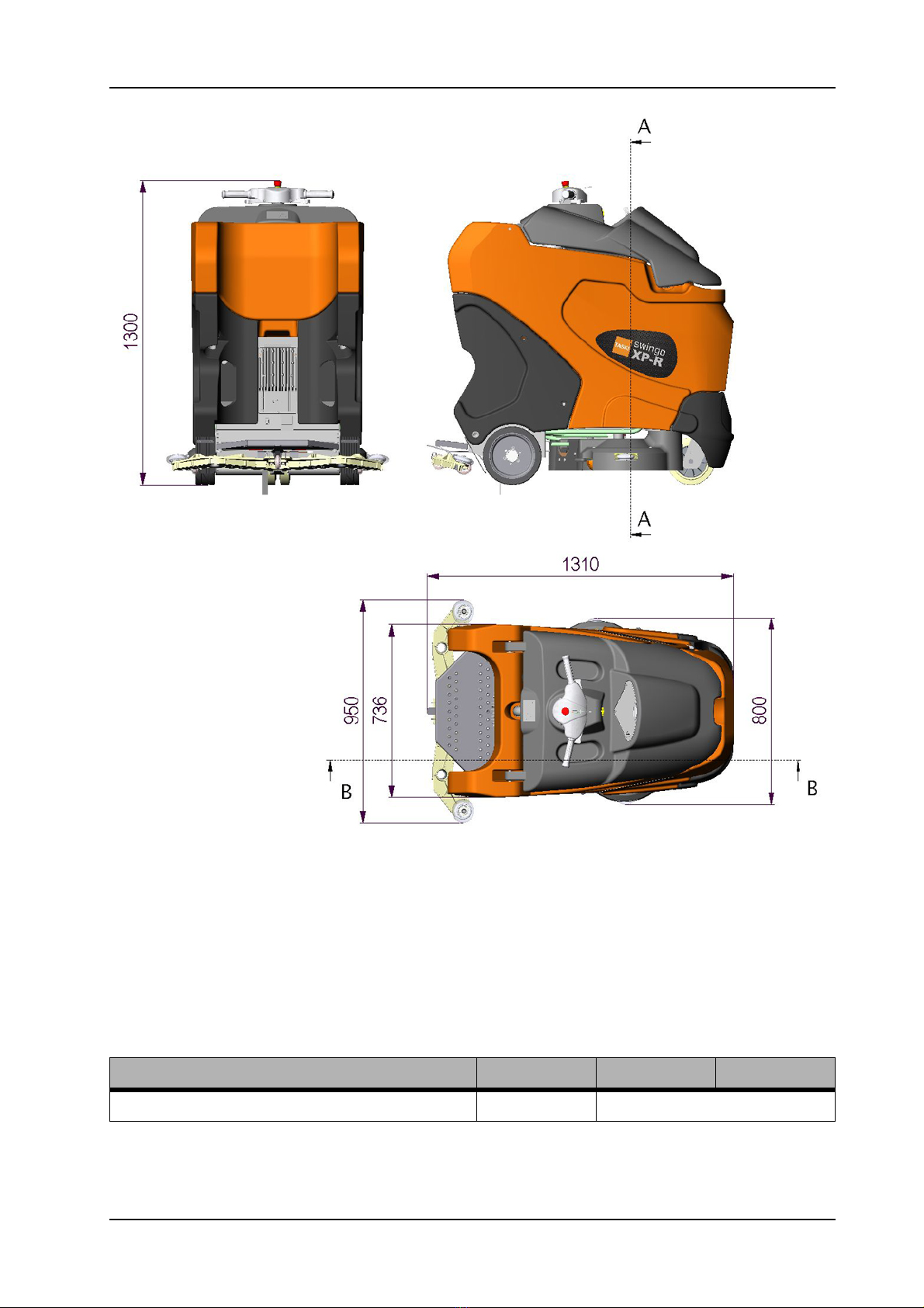
4.2.4 Dimensions and weights
Pos. Unit Value XP-R Value XP-M
Transportation speed (km/h) 6
Cleaning speed (km/h) 5.6
Reverse speed (km/h) 2.5
Ramp max. (%) 8
Table 4: Machine speed
Pos. Unit Value XP-R Value XP-M
Dimensions L/W/H (mm) 1310/950/1300
Door pass through with (without) squeegee (mm) 950 (800)
Battery compartment (two) L/W/H (mm) 530/190/275
Net weight without batteries; empty tank (kg) 207 196
Weight, ready to use (without driver) (kg) 452 438
Weight, ready for shipping (kg) 245 235
Max. floor pressure front (N/mm2) - -
Max. floor pressure rear (N/mm2) - -
Turn radius (between two walls) (mm) 1.9
Wheel diameter front (mm) 200
Wheel diameter rear (mm) 250
Table 5: Dimensions and weights
GTS Technical Manual
28. November 2014 Edition: V1.00/2014 4-4
Copyright © 2014, Diversey Care
04.1 swingo XP_M_R - technical data_V1.00.fm
Picture 1: Dimensions
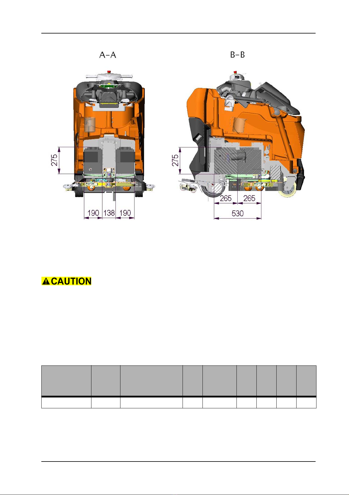
4.2.5 Battery
4.2.5.1 Battery compartment
Pos. Unit Value XP-R Value XP-M
Battery compartment L/W/H (mm) 530 x 190 x 275
Table 6: Battery compartment
GTS Technical Manual
28. November 2014 Edition: V1.00/2014 4-5
Copyright © 2014, Diversey Care
04.1 swingo XP_M_R - technical data_V1.00.fm
Picture 2: Battery compartment
4.2.5.2 Battery specifications
Please use batteries from Exide/Sonnenschein, as this is our preferred
partner.
BMS machines are set to a defined charging curve. Please use only
those type of batteries.
For the correct connection of the batteries, pay attention to the
voltage of each battery and the correct connection. Therefore refer to
e-spares.
Supplier Wet/
Dry
Type
Voltage
Ah
Length
Width
Height
Weight
Sonnenschein Dry GF06180V 6 180 (C5) 244 190 275 31
Table 7: Dry (GEL) batteries

GTS Technical Manual
28. November 2014 Edition: V1.00/2014 4-6
Copyright © 2014, Diversey Care
04.1 swingo XP_M_R - technical data_V1.00.fm
4.2.6 Charger
4.2.7 Brush system
Pos. Unit Value XP-R Value XP-M
Primary (V) 230 - 240
Primary (Hz) 50 - 60
Secondary (V) 24
Secondary (A) 25
Protection class (BMS model) II
Approval CE/CB
Cable length/BMS cable (m) 3.5
Table 8: Charger
Pos. Unit Value XP-R Value XP-M
Brush system (mm) 2 x 380 2 units
150 x 450
Brush motor (W) 750 2 x 130
Brush speed (rpm) 165 550
Brush pressure min. - max. (kg) 35-45-55 40-60-80
Brush pressure min. - max. (N/cm2) 0.16-0.2-
0.25
0.33-0.50-
0.67
Brush pressure min. - max. (g/cm2) 16-20-25 33-50-67
Table 9: Brush system
This manual suits for next models
1
Table of contents
Other Sealed Air Scrubber manuals


Popular Scrubber manuals by other brands


Viper
Viper FANG 18 C user manual

Nilfisk-Advance
Nilfisk-Advance Advance SC900 ST-28D Instructions for use

Nautilus
Nautilus MX3-500 operating manual

FAST CLEAN
FAST CLEAN Challenger RSS35 owner's manual

Nilfisk-Advance
Nilfisk-Advance MX 521 H operating instructions

Nobles
Nobles Speed Scrub 2001HD Operator and parts manual