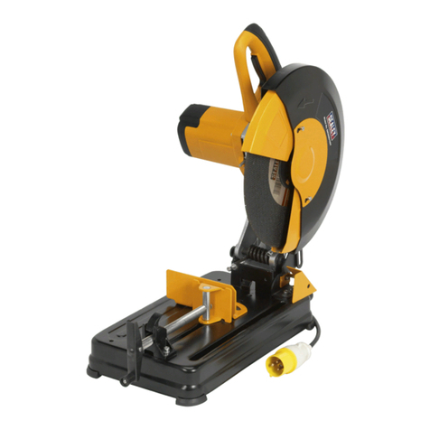
Sealey Quality MACHINERY SM225 User manual

INSTRUCTIONS FOR:
STEEL BLADED CUT-OFF SAWS
Models: SM225, SM250 & SM275
Thank you for purchasing a Sealey product. Manufactured to a high standard this product will, if used according to these instructions
and properly maintained, give you years of trouble free performance.
1. SAFETY INSTRUCTIONS
The use of symbols in this document is to attract your attention to possible danger. The symbols and warnings themselves do not eliminate any danger, nor are they substitutes for proper
accident prevention measures.
IMPORTANT: PLEASE READ THESE INSTRUCTIONS CAREFULLY. NOTE THE SAFE OPERATIONAL REQUIREMENTS, WARNINGS AND
CAUTIONS. USE THIS PRODUCT CORRECTLY AND WITH CARE FOR THE PURPOSE FOR WHICH IT IS INTENDED. FAILURE TO DO SO MAY
CAUSE DAMAGE OR PERSONAL INJURY AND WILL INVALIDATE THE WARRANTY. PLEASE KEEP INSTRUCTIONS SAFE FOR FUTURE USE.
1.2 GENERAL SAFETY
pWARNING! Disconnect the saw from the mains power, and ensure the cutting blade is at a complete standstill before attempting
to change accessories, service or perform any maintenance.
3Maintain the saw in good condition (use an authorised service agent).
3Replace or repair damaged parts. Use recommended parts only. Non authorised parts may be dangerous and will invalidate the warranty.
3Locate the saw in an adequate working area for its function. Ensure the surface is flat and firm. Keep area clean and tidy and free from
unrelated materials, and ensure there is adequate lighting.
3Keep the saw clean for best and safest performance and check moving parts alignment regularly.
pWARNING! Before each use check that blade is secure and that it is not worn or damaged. If worn or damaged replace immediately.
pWARNING! Keep guard and holding screws in place, tight and in good working order. Check regularly for damaged parts.
A guard, or any other part, that is damaged should be replaced with a new one, to ensure that it operates properly and performs its intended
function, before the tool is used. The safety guard is a mandatory fitting where saw is used in premises covered by the Health & Safety at
Work Act.
3Remove adjusting keys and wrenches from the machine and its vicinity before turning it on.
pWARNING! Wear approved safety eye protection, ear defenders, and gauntlets, and, if dust is generated, respiratory protection.
3Remove ill fitting clothing. Remove ties, watches, rings and other loose jewellery and contain long hair.
3Keep hands and body clear of the work table when operating the saw and position your body in line with the blade whilst cutting.
3Maintain correct balance and footing. Ensure the floor is not slippery and wear non-slip shoes.
3Always clamp workpiece in the base vice. NEVER hold a work piece by hand.
3Keep children and unauthorised persons away from the working area.
3Avoid subjecting blade to excessive strain, always ease blade down against workpiece (a harsh downward impact may break the blade or
teeth). Do not apply undue force on the handle in order to cut workpiece. Maintain a controlled cutting speed through the workpiece.
pWARNING! DO NOT switch the saw on whilst the blade is in contact with the workpiece. Bring the rotating blade to the workpiece.
and avoid un-intentional starting of the saw.
7DO NOT hold the workpiece by hand. Use base vice to secure the workpiece. SM225, 250 & 275 - (2) - 051102
1.1. ELECTRICAL SAFETY. p
p
WARNING! It is the users responsibility to read, understand and comply with the following:
You must check all electrical equipment and appliances to ensure they are safe before using. You must inspect power supply leads, plugs
and all electrical connections for wear and damage. You must ensure the risk of electric shock is minimised by the installation of appropriate
safety devices. An RCCB (Residual Current Circuit Breaker) should be incorporated in the main distribution board. We also recommend that
an RCD (Residual Current Device) is used with all electrical products. It is particularly important to use an RCD together with portable products
that are plugged into an electrical supply not protected by an RCCB. If in doubt consult a professional electrician. You may obtain a Residual
Current Device by contacting your Sealey dealer. You must also read and understand the following instructions concerning electrical safety.
1.1.1. The Electricity At Work Act 1989 requires all portable electrical appliances, if used on a business premises, to be tested by a qualified
Electrician at least once a year by using a Portable Appliance Tester (PAT).
1.1.2. The Health & Safety at Work Act 1974 makes owners of electrical appliances responsible for the safe condition of the appliance,
and the safety of the appliance operator. If in any doubt about electrical safety, contact a qualified electrician.
1.1.3. Ensure the insulation on all cables and the product itself is safe before connecting to the mains power supply.
See 1.1.1. & 1.1.2. above and use a Portable Appliance Tester (PAT).
1.1.4. Ensure that cables are always protected against short circuit and overload.
1.1.5. Regularly inspect power supply, leads, plugs and all electrical connections for wear and damage,
especially power connections, to ensure that none are loose.
1.1.6. Important: Ensure the voltage marked on the product is the same as the electrical power supply
to be used, and check that plugs are fitted with the correct capacity fuse. A 13 Amp plug may require
a fuse smaller than 13 Amps for certain products (subject to 1.1.10. below) see fuse rating at right.
1.1.7. DO NOT pull or carry the powered appliance by its power supply lead. Products such as welders
must not be pulled or carried by their output cables.
1.1.8. DO NOT pull power plugs from sockets by the power cable.
1.1.9. DO NOT use worn or damage leads, plugs or connections. Immediately replace or have repaired
by a qualified Electrician. A U.K. 3 pin plug with ASTA/BS approval is fitted. In case of damage,
cut off and fit a new plug according to the following instructions (discard old plug safely).
(UK only - see diagram at right). Ensure the unit is correctly earthed via a three-pin plug.
a) Connect the GREEN/YELLOW earth wire to the earth terminal E.
b) Connect the BROWN live wire to live terminal L.
c) Connect the BLUE neutral wire to the neutral terminal N.
After wiring, check there are no bare wires, that all wires have been correctly
connected and that the cable restraint is tight.
Double insulated products are often fitted with live (BROWN) and neutral (BLUE) wires only. Double insulated products are always marked
with this symbol . To re-wire, connect the brown and blue wires as indicated above. DO NOT connect the brown or blue to the earth terminal.
1.1.10. Some products require more than a 13Amp electrical supply. In such a case, NO plug will be fitted. You must contact a qualified Electrician
to ensure a 30 amp fused supply is available. We recommend that you discuss the installation of a industrial round pin plug & socket with your Electrician.
Blue
Neutral
wire
Yellow & Green
Earth wire
Cable
restraint
FUSE RATING
THIS PRODUCT MUST BE FITTED WITH A
10 Amp FUSE
Brown
Live
wire
8
510 - 18
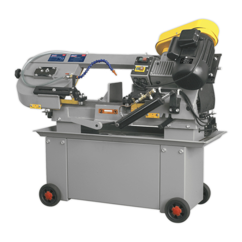
The SM225, SM250 & SM275 are circular saws designed to cut ferrous metal - including structural steel - bars and pipes. They should not be
used to cut any other materials. Blade guard, bar stop, integral workpiece vice and coolant system are included.
2. APPLICATION & SPECIFICATIONS
Blade sizes . . . . . . . . . . . . . . . . . . . . . . . . . . . . . . . . .See Blade Chart
Max.cutting capacity . . . . . . . . . . . . . . . . . . . . . . . . . .See Blade Chart
Max. vice opening (225/250/275) . . . . . . . . . . . . . . . . .70/100/100 mm
Motor (225/250/275) . . . . . . . . . . . .0.75/0.9/1.1 kW 230Vac 1ph 50Hz
Motor speed . . . . . . . . . . . . . . . . . . . . . . . . . . . . . . . . . . . . .1400 rpm
Blade speeds (225/250/275) . . . . . . . . . . . . . . . . . . . . . .52/52/40 rpm
Mitre cuts (225) . . . . . . . . . . . . . . . . . . . . . . . . . . . . . . . . . .0O-45O right
Mitre cuts (250/275) . . . . . . . . . . . . . . . . . . . . . . . . . . . . . . .45O-0O-45O
Coolant . . . . . . . . . . . . . . . . . . . . . .Water + Sealey SCO/5L soluble oil
Coolant capacity (225/250/275) . . . . . . . . . . . . . . . . . . . . . . .1/3/3 litre
Oil (gear box) . . . . . . . . . . . . . . . . . . . . .AGIP ACER 320 or equivalent
Oil capacity . . . . . . . . . . . . . . . . . . . . . . . . . . . . . . . . . . . . . . .0.2 litres
Weight (225/250/275) . . . . . . . . . . . . . . . . . . . . . . . . . . . . .32/85/98 kg
Sound pressure level- average (225/250/275) . . .84.2/83.2/83.2 dB (A)
- peak . . . . . . . . . . . . . . . . . . . . . . .90.6 dB (A)
Specifications:
7DO NOT force the saw to achieve a task it was not designed to perform.
7DO NOT allow untrained persons to operate the saw.
7DO NOT get the saw wet or use in damp or wet locations or areas where there is condensation.
pWARNING! DO NOT use saw where there are flammable liquids, solids or gases such as petrol, paint solvents, waste wiping rags etc.
7DO NOT operate the saw if any parts are missing or damaged as this may cause failure or possible personal injury.
7DO NOT remove the safety guard whilst in use.
7DO NOT attempt to remove a workpiece until the blade has stopped rotating.
7DO NOT touch the workpiece close to the cut as it will be very hot. Allow to cool.
7DO NOT leave the saw operating whilst unattended.
7DO NOT operate the saw when you are tired, under the influence of alcohol, drugs or intoxicating medication.
3When not in use switch the saw off and isolate from the power supply.
Blade Chart
Workpiece SM 225 SM 275SM 250
Tube Blade 225mm dia. x 2mm Blade 275mm dia. x 2.5mmBlade 250mm dia. x 2mm
Wall thicknessDia. mm Tooth pitch mm No. teeth No. teethTooth pitch mmNo. teethTooth pitch mm
10 - 80 <2 3 230 28032503
20 - 80
10 - 80
4 - 10
2 - 4
90
140
11081008
17051605
>40
30 - 40
18 - 30
Solid bar
8
5
-
10
-
70
90
140
70
90
12
10
-
80
-
10
11081008
17051605
Description:
1. Saw assembly
2. Handle mouldings (2) & screws (3)
3. Micro switch
4. Switch button
5. Control lever
6. End stop
7. Allan keys (sizes 3, 4, 5, 6, 14)
3.1. Unpack the product and check that all components and tools (five Allan keys) are present and
undamaged.If any problem is noted contact your supplier immediately.
3. CONTENTS & ASSEMBLY
fig 1
pWARNING! For safe handling and movement use a lift truck or crane. Slings should be located as shown in fig.1.
fig 3
3.2. Set the saw on a flat, stable work bench, or surface strong enough to support the saw and any workpiece.
Mount the SM250/275 to the working surface (or pedestal) using the mounting holes provided in the base.
3.3. Assembly of control lever
3.3.1. Check control lever (fig.2-F) cable slot for burrs or sharp edges - rectify if found - and then screw lever into hole A (fig.3) in saw
head. Position lever with cable slot to one side and and the handle fixing hole facing downwards. Tighten lock nut.
3.3.2. Undo the four screws holding the cover ( fig.2-A ) onto the handle B and remove it. Feed the switch cable C into the hole in the end of
the handle and push it through until it emerges from the cover aperture. Connect the cable to the microswitch D as indicated in fig.2
and seat the microswitch into the moulding with the operating button facing downwards. Retain the microswitch by placing the cover
over it and fasten the cover with the four screws.
fig 2
SM225, 250 & 275 - (2) - 051102

3.3.3. Ensure that the grub screw E is not protruding into the hole for the lever. Lay the cable into the
cable slot in the side of the lever and slide the handle down onto the end of the lever until the grub
screw E is aligned with the screw fixing hole G. Insert a hex key into the grub screw and screw it
down into the lever.
3.4. Fitting blade
3.4.1. Fully raise motor block by pushing control lever towards rear.
3.4.2. Remove screw (fig.4.1) and rotate blade guard towards the rear.
3.4.3. Remove blade retaining screw (fig.4.2) and blade flange (3).
3.4.4. Locate blade on drive face ensuring that rotation arrow on blade matches that on blade guard.
Refit flange and screw.
3.4.5. Rotate blade guard forward and refit screw (1). Confirm that guard will prevent fingers
touching blade.
3.5. Fill coolant tank - see chapter 2 - Specifications. Confirm tap (fig 8.1) is open.
3.6. Check sight-glass and visually confirm that there is oil in the gearbox.
3.7. Pull control lever forward as far as possible, to lower blade, and confirm that blade is clear of saw
base in this position. If blade is touching base then adjust abutment screw (fig.3.B) to achieve
clearance. Note: Fig.3 shows typical abutment screw locations which vary slightly between models.
3.8. Raise blade as far as possible and confirm that rear of motor is clear of base. If motor is touching
base then adjust abutment screw (fig.3.C) to achieve clearance.
3.9. Confirm all tools have been removed from saw, main switch (SM225 fig.5.1, SM250/275 fig.6.1) is
Off and blade guard is in position.
3.10. Connect mains lead to power supply, having confirmed that supply matches voltage/phases
as shown on motor plate.
SM250/275 - Confirm that Emergency Stop switch (fig.6.2) is in the run position (out) and switch 3
is in position 1.
3.11. Turn main switch On and operate switch button in control lever handle - motor will run. Confirm
motor stops when either the button is released or the main switch is turned Off or (SM250/275)
the Emergency Stop is pushed. During this test confirm that blade is rotating in direction as shown
by arrow on guard and that coolant pump is operating.
Note: SM250/275 - Main switch is lockable to prevent unauthorised use.
4. OPERATING INSTRUCTIONS
p WARNING! Before sawing ensure you wear approved safety goggles, ear defenders, appropriate dust mask if saw generates dust
and safety gloves, and that all other safety instructions in chapter 1 are followed carefully.
4.1. Securing workpiece.
4.1.1. Ensure the saw is switched off at the main switch and then secure workpiece in the base vice (fig.7.1).
We recommend that you place a block of wood (slightly narrower than the work piece) in the vice below the item to be cut to act as a support.
4.1.2. When cutting a long workpiece use additional supports along the length.
4.1.3. If multiple workpieces of the same length are required, screw end stop into vice base, secure with locknut and adjust to give the
appropriate length.
4.2. The On and Off switch.
With saw connected to mains power supply turn on main switch. Start saw by depressing the button located in the handle (fig.7.2).
Release button to stop saw.
fig 4
fig 6
4.3. Operating.
pWARNING! DO NOT switch the saw on whilst the blade is in contact with the work piece. Bring the rotating blade to the workpiece.
4.3.1. The blade must be running at maximum speed and coolant flowing before attempting to lower the cutting edge onto workpiece.
4.3.2. Lower the blade slowly and smoothly towards the workpiece (avoid jerky movements).
4.3.3. Exert adequate downward pressure on the handle to allow cutting according to the type and size of the material you are working with.
Avoid subjecting the blade to excessive strain, always ease the blade down against workpiece (a harsh downward impact may break
the blade or damage the teeth).
Do not apply undue force on the handle in order to cut workpiece. Maintain a controlled cutting speed through the workpiece.
4.3.4. When cutting heavy material, move the blade intermittently through the workpiece with steady progression.
4.4. Completing the cut.
4.4.1. When cutting is completed, carefully raise the blade to its full extent.
4.4.2. Release the button and wait until the blade has fully stopped before attempting to remove the workpiece.
4.5. Mitre cutting.
To cut the workpiece at an angle the saw head must be adjusted.
4.5.1. SM225 - to effect an angled cut, loosen the saw support clamp screw and rotate the saw/motor assembly to the required
angle, reading the graduated scale, up to a maximum of 45O.
4.5.2. Re-tighten the clamp screw and make the cut.
4.5.3. SM250/275 - to effect an angled cut, move the locking lever (fig.7.3 & fig.8.2) to position 2 and rotate the saw/motor assembly to
the required angle, reading the graduated scale (fig.7.4), up to a maximum of 45Oin either direction.
4.5.4. Move the locking lever back to position 1 and make the cut.
fig. 5
SM225, 250 & 275 - (2) - 051102

5. CHANGING SAW BLADE.
5.1. Removing blade
5.1.1. Place saw head in the up position.
5.1.2. Move the blade guard backwards by removing screw (fig.4.1).
5.1.3. Remove blade retaining screw (fig.4.2), blade flange (3) and blade.
5.1.4. Clean parts before re-assembly.
5.2. Fitting blade
5.2.1. Position the blade on the drive flange (fig.4.4) having checked mating faces for cleanliness.
5.2.2. Fit outer flange (3) and retaining screw (2) and tighten.
5.2.3. Move the guard back to its original position and replace screw (1).
5.2.4. Check that the guard is free to rotate as saw blade is raised and lowered.
6. MAINTENANCE
p
p
WARNING! Ensure the saw is isolated from the mains power supply before attempting
any maintenance.
6.1. Regularly clean the dust which accumulates inside the protective guard and on the external parts.
6.2. Every 1000 operating hours: Clean and grease saw head pivot, saw head support, moving guard and vice. Dis-assemble
vice of SM250/275 by removing jaw (fig.8.3) and then turning hand wheel (4) to withdraw vice slide.
After re-assembly apply a small amount of oil to oil hole (fig.9.4).
Drain gearbox oil - remove filler cap (fig.3.D)and sight-glass/drain screw (fig.4.5). After draining
replace drain screw and refill via filler cap hole. Replace filler cap.
6.3. Every 50 hours: Drain coolant tank via tap (fig.8.1) after removing pipe (5). Remove screws (6) and cover (7),
clean sediment from tank, replace cover and screws. Check filter (fig.8.8) and replace if necessary.
Refit pipe to tap and refill tank. Take care not to splash coolant/swarf onto motor or switch box.
SM250/275 -check that the locking lever (fig.8.2 & fig.9.1) firmly locks and releases the saw head.
To adjust, loosen grub screw (fig.9.2), adjust nut (3) until correct lever operation is achieved and then
re-tighten grub screw.
Declaration of Conformity We, the sole importer into the UK, declare that the products listed here
are in conformity with the following EEC standards and directives
The construction files for these products are held by the Manufacturer and may be inspected on request
by contacting Jack Sealey Ltd.
For Jack Sealey Ltd. Sole importer into the UK of Sealey Quality Machinery
Steel Bladed Cut-Off Saws
Models SM225, SM250 & SM275
73/23/EEC Low Voltage Directive (S.I. 1994/3260)
89/336/EEC EMC Directive (S.I. 1992/2372 & Amendments).
98/37/EEC Machinery Directive
(Safety) Regulations 1992 (SI 1992 No. 3073) as amended
93/68/EEC CE Marking Directive
EN 60204-1 1998 Safety of Machinery
Signed by Mark Sweetman 1st July 1999
01284 757500
E-mail:
sales@sealey.co.uk
01284 703534
Sole UK Distributor
Sealey Group,
Bury St. Edmunds, Suffolk.
NOTE: It is our policy to continually improve products and as such we reserve the right to alter data, specifications and component parts without prior notice.
IMPORTANT: No liability is accepted for incorrect use of this equipment. WARRANTY: Guarantee is 12 months from purchase date, proof of which
will be required for any claim. INFORMATION: For a copy of our catalogue call us on 01284 757525 and leave your full name, address and postcode.
s
s
DANGER! The use of damaged blades is dangerous and may cause personal injury.
p WARNING! Ensure the saw is isolated from the mains power supply before attempting to change the blade.
Before using a saw blade check that it is undamaged, undistorted and the teeth are sharp.
IMPORTANT! Saw blades used with this machine shall be of the specified diameter and thickness, with an adequate speed rating
and suitable for the material being cut.
fig 7
fig 8
fig 9
Web address: www.sealey.co.uk
SM225, 250 & 275 - (2) - 051102
This manual suits for next models
2
Table of contents
Other Sealey Saw manuals

Sealey
Sealey SA348 User manual

Sealey
Sealey SMS255.V3 User manual

Sealey
Sealey HTS8 User manual

Sealey
Sealey SA345.V2 User manual

Sealey
Sealey TS1098 User manual

Sealey
Sealey SCS1400 User manual

Sealey
Sealey SM6582 User manual

Sealey
Sealey SM64.V2 User manual

Sealey
Sealey Quality MACHINERY SM2504 User manual

Sealey
Sealey CP1208 User manual

Sealey
Sealey SA650.V3 User manual

Sealey
Sealey SM1303.V2 User manual

Sealey
Sealey CP20VRSX User manual

Sealey
Sealey SM35CE.V4 User manual

Sealey
Sealey MG214/230V.V2 User manual

Sealey
Sealey sm1302.v2 User manual

Sealey
Sealey SM35CE User manual

Sealey
Sealey SA346.V2 User manual

Sealey
Sealey SM355D110V User manual

Sealey
Sealey SM2254 User manual