Sealey TS1098 User manual

INSTRUCTIONS FOR:
TABLE SAW
Model No: TS1098
The use of symbols in this document is to attract your attention to possible danger. The symbols and warnings themselves do not eliminate any danger, nor are they substitutes for proper
accident prevention measures.
Thank you for purchasing a Sealey product. Manufactured to a high standard this product will, if used according to these instructions
and properly maintained, give you years of trouble free performance.
1. SAFETY INSTRUCTIONS
IMPORTANT: PLEASE READ THESE INSTRUCTIONS CAREFULLY. NOTE THE SAFE OPERATIONAL REQUIREMENTS, WARNINGS AND
CAUTIONS. USE THIS PRODUCT CORRECTLY AND WITH CARE FOR THE PURPOSE FOR WHICH IT IS INTENDED. FAILURE TO DO SO MAY
CAUSE DAMAGE AND/OR PERSONAL INJURY, AND WILL INVALIDATE THE WARRANTY. PLEASE KEEP INSTRUCTIONS SAFE FOR FUTURE USE.
TS1098 - 0016 - (2) - 140700
CHAPTER CONTENT
1. SAFETY
2. INTRODUCTION & DESCRIPTION
3. SPECIFICATIONS & ASSEMBLY
4. ADJUSTMENT & SETTING
5. OPERATING
RECORD OF MODEL & SERIAL NUMBERS.
Model No:
Serial No:
Date of Purchase:
1.1. ELECTRICAL SAFETY. p
p
p
WARNING! It is the users responsibility to read, understand and comply with the following:
You must check all electrical equipment and appliances to ensure they are safe before using. You must inspect power supply leads, plugs and
all electrical connections for wear and damage. You must ensure the risk of electric shock is minimised by the installation of appropriate safety
devices. An RCCB (Residual Current Circuit Breaker) should be incorporated in the main distribution board. We also recommend that an RCD
(Residual Current Device) is used with all electrical products. It is particularly important to use an RCD together with portable products that are
plugged into an electrical supply not protected by an RCCB. If in doubt consult a qualified electrician. You may obtain a Residual Current Device
by contacting your Sealey dealer. You must also read and understand the following instructions concerning electrical safety.
1.1.1. The Electricity At Work Act 1989 requires all portable electrical appliances, if used on business premises, to be tested by
a qualified electrician, using a Portable Appliance Tester (PAT), at least once a year.
1.1.2. The Health & Safety at Work Act 1974 makes owners of electrical appliances responsible for the safe condition of the appliance
and the safety of the appliance operator. If in any doubt about electrical safety, contact a qualified electrician.
1.1.3. Ensure the insulation on all cables and the product itself is safe before connecting to the mains power
supply. See 1.1.1. & 1.1.2. above and use a Portable Appliance Tester (PAT).
1.1.4. Ensure that cables are always protected against short circuit and overload.
1.1.5. Regularly inspect power supply, leads, plugs and all electrical connections for wear and damage,
especially power connections, to ensure that none is loose.
1.1.6. Important: Ensure the voltage marked on the product is the same as the electrical power supply
to be used, and check that plugs are fitted with the correct capacity fuse. A 13 amp plug may require
a fuse smaller than 13 amps for certain products (subject to 1.1.10. below) see fuse rating at right.
1.1.7. DO NOT pull or carry the powered appliance by its power supply lead.
1.1.8. DO NOT pull power plugs from sockets by the power cable.
1.1.9. DO NOT use worn or damage leads, plugs or connections. Immediately replace or have repaired by
a qualified electrician. A U.K. 3 pin plug with ASTA/BS approval is fitted. In case of damage, cut off
and fit a new plug according to the following instructions (discard old plug safely).
(UK only - see diagram at right). Ensure the unit is correctly earthed via a three-pin plug.
a) Connect the GREEN/YELLOW earth wire to the earth terminal E.
b) Connect the BROWN live wire to live terminal L.
c) Connect the BLUE neutral wire to the neutral terminal N.
After wiring, check there are no bare wires, that all wires have been correctly connected, that the cable outer insulation
extends beyond the cable restraint and that the restraint is tight.
Double insulated products are often fitted with live (BROWN) and neutral (BLUE) wires only. Double insulated products are always marked with
this symbol . To re-wire, connect the brown & blue wires as indicated above. DO NOT connect the brown or blue to the earth terminal.
1.1.10. Some products require more than a 13 amp electrical supply. In such a case, NO plug will be fitted. You must contact a qualified electrician
to ensure a 30 amp fused supply is available. We recommend you discuss the installation of a industrial round pin plug and socket with your electrician.
1.1.11. Cable extension reels. When a cable extension reel is used it should be fully unwound before connection. A cable reel with an RCD
fitted is recommended since any product which is plugged into the cable reel will be protected. The section of the cable on the cable
reel is important. 1.5mm2section cable is a minimum but to be absolutely sure that the capacity of the cable reel is
suitable for this product and for others that may be used in the other output sockets, we recommend the use of 2.5mm2section cable.
B
B
l
l
u
u
e
e
N
N
e
e
u
u
t
t
r
r
a
a
l
l
w
w
i
i
r
r
e
e
Y
Y
e
e
l
l
l
l
o
o
w
w
&
&
G
G
r
r
e
e
e
e
n
n
E
E
a
a
r
r
t
t
h
h
w
w
i
i
r
r
e
e
C
C
a
a
b
b
l
l
e
e
r
r
e
e
s
s
t
t
r
r
a
a
i
i
n
n
t
t
FUSE RATING
THIS PRODUCT MUST BE FITTED
WITH A:
13 AMP FUSE
B
B
r
r
o
o
w
w
n
n
L
L
i
i
v
v
e
e
w
w
i
i
r
r
e
e
1.2 GENERAL SAFETY
3Familiarise yourself with this products application and limitations, as well as the specific potential hazards peculiar to the saw.
pWARNING! Disconnect the saw from the mains power before changing accessories, servicing or performing any maintenance.
3The machine must only be serviced by a qualified person or service agent. Contact your Sealey dealer for information.
3Permanently mount the saw on a supporting surface strong enough to take the weight of the machine and workpiece during operation.
3Ensure there is an adequate dust extraction area under the saw. Follow mounting instructions in chapter 3 carefully.
3Ensure operating area for the saw is adequate, keep area clean & tidy and free from unrelated materials. Ensure there is adequate lighting.
3Wood dust can be harmful to health by inhalation and skin contact and concentrations of small dust particles in the air can form an
explosive mixture. Ensure there is adequate ventilation and that the saw is attached to a dust-extraction unit.
3Maintain the saw in good condition, check moving parts alignment regularly. Keep saw blades clean & sharp. ,
01284 757500
E-mail:
sales@sealey.co.uk
01284 703534

TS1098 - 0016 - (2) - 140700
2. INTRODUCTION & DESCRIPTION
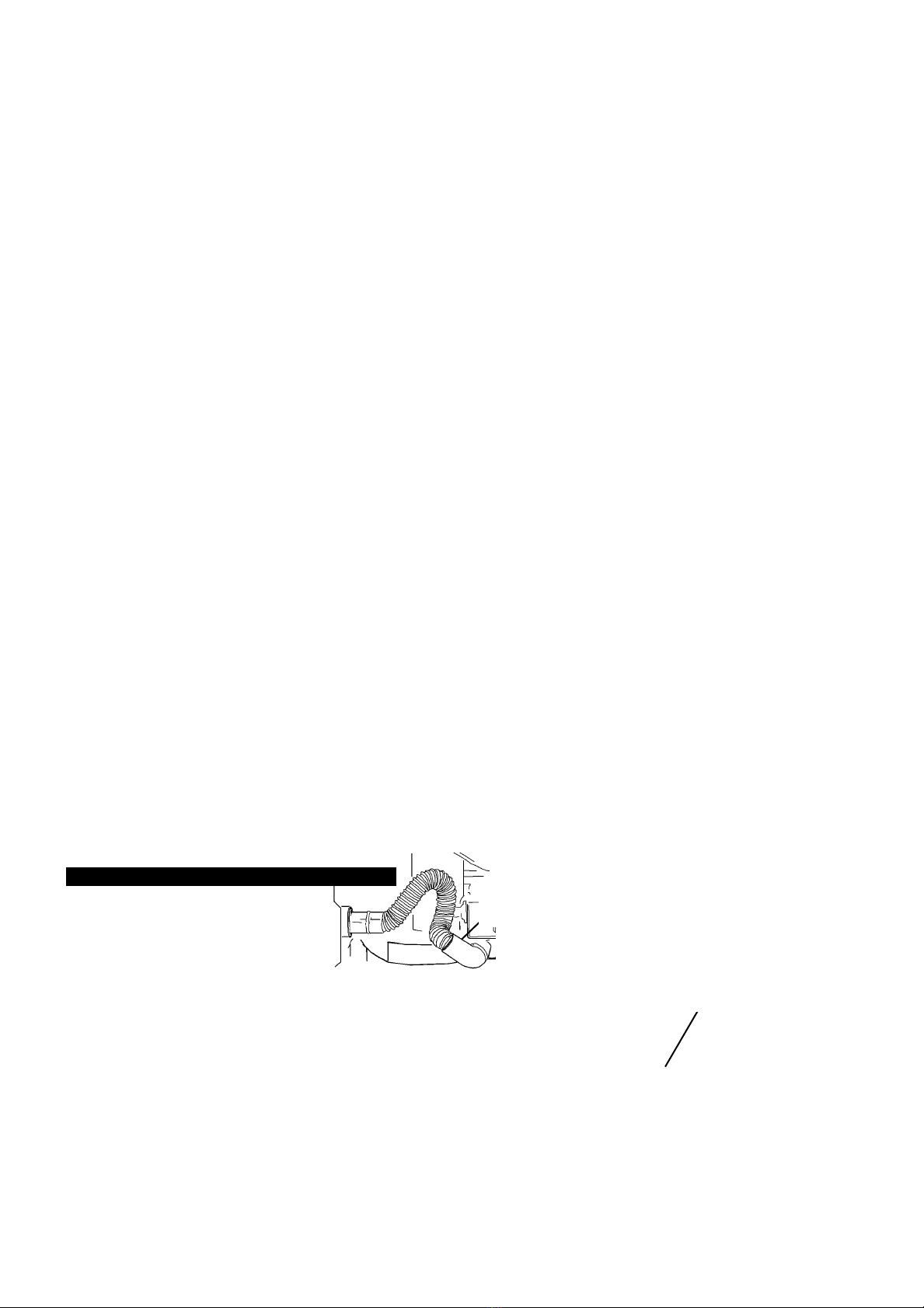
The TS10/98 Professional quality table top
saw is fully approved to CE regulations and
backed by independent laboratory
certification. Compound angle cutting
permitted by full tilt and height adjustment
of up to 450of cutting arbor. The unit is fitted
with a No-Volt safety switch and approved
splitter for added user safety.
1. Support table.
2. Blade guard with splitter.
3. Mitre gauge.
4. Self-aligning fence with lock.
5. Mounting base holes.
6. Blade tilt & height handle.
7. On/Off switch.
8. Base cover (on the underside of unit).
9. Mitre slot (left, the right slot is obscured by the fence).
10. Tilt locking knob.
3Replace or repair damaged parts. Use recommended parts only. Non authorised parts may be dangerous and will invalidate the warranty.
pWARNING! Keep all guards and holding screws in place, tight and in good working order. Check regularly for damaged parts.
A guard or any other part that is damaged should be checked to ensure that it will operate properly and perform its intended function
before the tool is used. The safety guard is a mandatory fitting where saw is used in premises covered by the Health & Safety at Work Act.
3Before commencing work, ensure the saw blade is set to cut in the correct direction, securely fastened, sharp and is compatible with the
machine, spindle speed, and the material to be cut. Never use saw blade if damaged, bent or warped. Use only recommended saw blades.
3Remove adjusting keys and wrenches from the machine and its vicinity before turning it on.
3Machine operators must have received sufficient training and instructions as to the dangers arising in connection with the machine, the
precautions to be observed and the requirements of the Wood working Machines Regulations which apply, operators must under
the adequate supervision of a person who has a thorough knowledge and experience of the machine and the required guards.
pWARNING! Wear approved safety eye protection, ear defenders, and if dust is generated respiratory protection.
3Remove ill fitting clothing. Remove ties, watches, rings, and other loose jewellery, and contain long hair.
3Keep hands and body clear of the work table when operating the saw.
3Maintain correct balance and footing. Ensure the floor is not slippery and wear non slip shoes.
3Keep children and unauthorised persons away from the working area.
3Avoid unintentional starting and never leave the saw operating whilst unattended.
7DO NOT force the saw to achieve a task it was not designed to perform, and ensure operators are trained to use the saw.
7DO NOT get the saw wet or use in damp or wet locations or areas where there is condensation.
7DO NOT use saw where there is flammable liquids, solids or gases such as paint solvents, including waste wiping or cleaning rags etc.
7DO NOT operate the saw if any parts are damaged or missing as this may cause failure or possible personal injury.
7DO NOT operate the saw when you are tired, under the influence of alcohol, drugs or intoxicating medication.
1.3. SPECIFIC SAW SAFETY RULES
3Remove sawdust frequently. Unplug from mains power. Clean out sawdust from interior of saw to prevent potential fire hazard.
3Keep splitter and anti-kickback fingers and guard in place and operational, and replace table insert when worn.
3Ensure you select the appropriate saw blade for the material to be cut.
pWARNING! Before each use, check that the saw blade is secure and not worn or damaged.
3Use the guard, splitter and anti-kickback fingers on all through-sawing operations. Through-sawing operations are those when the blade cuts
completely through the workpiece as in ripping or cross-cutting.
3Check workpiece to ensure there are no nails or other items which may foul on the saw blade.
3Hold the work firmly against the mitre gauge or fence.
3Only feed the workpiece into the blade against the rotation of the blade.
3When cutting moulding, never run the stock between the fence and the moulding cutter-head.
3Avoid subjecting the saw blade to excessive strain, never force a workpiece. Maintain a controlled adequate progression.
3Should a saw blade jam switch the power off immediately to prevent damage to the motor.
3TO AVOID WORKPIECE KICKBACK (When a workpiece is violently thrown back toward yourself).
a) Keep the blade sharp. b) Keep rip fence parallel to the saw blade. c) DO NOT release the workpiece before it is pushed all the way
past the saw blade. d) DO NOT rip work that is twisted or warped or does not have a straight edge to guide along the fence.
3Use a push stick for ripping narrow stock. refer to ripping applications and push stick patterns in manual relating to the use of push stick.
3Provide adequate support to the rear and sides of the saw table for wide or long workpieces.
7DO NOT use your hands (free-hand) to guide the workpiece. Hold work firmly against the mitre or fence to guide work through the saw.
7DO NOT place yourself in an awkward operating position where a sudden slip could cause your hand to move into the cutting blade.
7DO NOT stand or have any part of your body in line with the path of the saw blade, and keep your hands out of the line of the saw blade.
7DO NOT use the fence as a cut-off gauge when cross-cutting.
7DO NOT hold what will become the off-cut (the waste part of workpiece).
pWARNING! DO NOT reach behind or over the saw blade with your hand or arms.
pWARNING! DO NOT attempt to free a jammed saw blade without first switching off or removing the plug from the mains power supply.
7DO NOT cut metal materials, and substances that may produce toxic dust. Saw must only be used to cut wood or wood type substances.
7DO NOT use solvents to clean plastic parts which may damage them. Use a soft damp cloth only.
3Store blades in a safe, dry childproof location.
3When not in use switch the saw off, remove plug from the power supply. ,
9
10

Motor . . . . . . . . . . . . . . . . . . . . . . . . .230V - 2.0 hp
Saw Blade Ø . . . . . . . . . . . . . . . . . . . . . . . .250mm
Arbor Ø . . . . . . . . . . . . . . . . . . . . . . . . . . . .15.8mm
Speed . . . . . . . . . . . . . . . . . . . . . . . . . . . .4800rpm
Max Depth of 90Ocut . . . . . . . . . . . . . . . . . . .76mm
Max Depth of 45Ocut . . . . . . . . . . . . . . . . . . .64mm
Rip to right of blade . . . . . . . . . . . . . . . . . . .203mm
Table Size . . . . . . . . . . . . . . . . . . . . . . .660 x 450mm
Table Extension Size . . . . . . . . . . . . . . .660 x 150mm
Table size with extension . . . . . . . . . . . .865 x 750mm
Dust extraction Ø . . . . . . . . . . . . . . . . . . . . . . . .35mm
Sound power level . . . . . . . . . . . . . . . . . .109.51 dB(A)
Sound Pressure level . . . . . . . . . . . . . . . . 98.71 dB(A)
3. SPECIFICATIONS & ASSEMBLY
pWARNING! ENSURE THE SAW IS NOT CONNECTED TO THE MAINS POWER BEFORE COMMENCING ASSEMBLY.
3.1. HAND WHEEL ASSEMBLY.
The wheel handle allows fast turning of the hand wheel. When correctly assembled it should rotate freely with a small amount of play.
Take the handle (fig 1.B), round head bolt (A) and a hex nut (C) from carton content.
3.1.1. Pass the round head bolt through the large end of the handle.
3.1.2. Screw the hex nut onto the end of the round head bolt hand tight only.
3.1.3. Screw the handle assembly into the hand wheel until the hex nut makes contact with the face of the wheel.
3.1.4. Lock the hex nut against the wheel (not the handle). Check to ensure the handle rotates freely.
3.2. SPLITTER & BLADE GUARD ASSEMBLY.
pWARNING! The splitter and guard must be correctly assembled and aligned with the saw blade in order to prevent kickback.
3.2.1. Position the blade (fig 2. A) at 900to the table and lock the blade in place. To raise the blade see chapter 4.
3.2.2. Turn the saw onto its side and remove the base cover. Pass the splitter (fig 2.B) through the cutting slot and view the underside of the
saw to align with the two screw holes on the side securing plate (fig 3.1).
3.2.3. Pass two hex bolts with washer through the splitter holes and lightly secure but do not tighten at this stage (fig 3.1).
3.2.4. Using a straight edge, check that the splitter is correctly aligned with the saw blade (fig 4.A). If adjustment is required, move the
splitter until aligned and then fully tighten the securing hex bolts (fig 3.1). ,
fig 3. fig 4.
fig 2.
fig 1.
3.3. MITRE GAUGE (fig 5).
Place mitre gauge on working table and position it in the left hand slot in the table surface.
3.4. SAW STAND OR BENCH.
The saw must be mounted on a sturdy workbench (or similar). Ensure the supporting surface
is strong enough to take the weight of the saw and the workpiece during operation.
3.5. DUST HOLE & SAW MOUNTING HOLES (fig 6).
An adequate dust hole must be provided to allow sawdust to fall through.
3.5.1. Place saw onto chosen mounting bench or stand & check it is square to
edge of the supporting surface.
3.5.2. Mark location of four base mounting bolts, remove saw & drill four 8mm0holes.
3.5.3. Cut a 280mm2hole in surface. To do so draw diagonal lines from each
mounting hole, measure outward from centre point where lines cross
140mm each way (ensuring lines are square with the four corner holes)
& cut hole out accordingly. (An alternative hole measurement is 305mm).
pWARNING! Failure to provide hole will cause dust to build up under
saw which may harm the motor and could cause a fire.
Note: Although there is a hole for the dust to fall, the saw base plate
must be correctly fitted.
3.6. SAW LOCATION & FIXING.
3.6.1. Position the saw in an adequate area with enough clearance to allow
room when working with large workpieces.
3.6.2. Ensure there is adequate lighting & that you can see saw blade clearly.
3.6.3. Check supporting surface to ensure it is strong enough to take weight
of the bench, saw and workpiece.
3.6.4. Mount saw on bench by passing bolts through the base holes (fig 6 & 7).
Note: If you purchase a saw Floor Stand ensure you use adequate
securing bolts that will pass through the stand, base cover and saw base.
pWARNING! Wood dust can be harmful to health by inhalation and skin contact
and concentrations of small dust particles in the air can form an explosive mixture. Ensure there is
adequate ventilation and that the saw is attached to a dust-extraction unit.
3.7. DUST EXTRACTION UNIT.
View picture to the right and note location of the internal dust extraction ducting. Connect your
dust extraction unit to the ducting outlet and use in accordance with the extractor instructions.
For information regarding dust extraction systems, contact your Sealey dealer. ,
fig 6.
TS1098 - 0016 - (2) - 140700
fig 7.
fig 5.
Dust extraction
ducting

4.1. ON/OFF SWITCH
The saw has an magnetic switch located on the left front side of machine. Push the l button for ON and the 0 for OFF.
pWARNING! ENSURE SAW IS SWITCHED OFF & DISCONNECT FROM THE MAINS POWER BEFORE MAKING ADJUSTMENTS OR SETTING SAW.
4.2. TO RAISE OR LOWER THE BLADE.
Turn the hand wheel (fig 8. 6) clockwise to lower the blade, and anti-clockwise to raise the blade.
4.3. BLADE TILT CONTROL (for bevel cross cutting)
To tilt the blade, loosen tilting lock handle knob (fig 1 A) and move the wheel assembly (6), until the blade is at the desired angle
by reading from the angle scale along the bottom of the wheel, then re-tighten the locking knob.
pWARNING! Ensure the tilt lock handle (A) remains securely locked so that it will not move during cutting.
4.4. MITRE GAUGE
For straight cross-cutting the blade is set at 900to the table. The mitre gauge is used to cut a workpiece at an angle to the blade.
To do so position the mitre gauge in either the right or left hand channel and set the mitre to the required angle for cutting.
sCAUTION! If you are bevel cross cutting (i.e.blade is tilted) ensure you place mitre in the RIGHT hand table slot
only. This will ensure that the blade is tilted away from the mitre gauge and your hands.
4.5. STOP ADJUSTMENT for 900& 450 BLADE SETTING
For rapid and accurate positioning of the saw blade at 900& 450to the table proceed as follows:
4.5.1. Raise the saw blade to its maximum height by turning the wheel anti-clockwise. (fig 8.6).
4.5.2. To set the blade at 900, place a square on the table with one end of the square against the blade (fig 10. A).
Check to ensure the blade is set at 900to the table. If not, loosen hex screw (fig 10. B) a few turns and move
the blade tilting mechanism until the blade is at 900and re-tighten screw (B) and the blade tilting lock knob (fig 8. A).
4.5.3. To set the blade at 450, loosen the blade tilting lock knob (fig 8.A), move blade tilting mechanism as far to the left as possible.
4.5.4. Place square (fig 11.A) on the table with one end of the square against the blade.
4.5.5. Check to see that the blade is set at 450to the table and that there are no gaps between the square and the blade.
4.5.6. Make any necessary adjustments by turning screw (fig 11.C) and checking to close gaps between the square and blade. ,
4. ADJUSTMENT & SETTINGS
fig 8. fig 9. fig 10. fig 11.
fig 12.
fig 13.
fig 14.
4.6. TO CHANGE THE BLADE
4.6.1. Undo the saw base retaining bolts and carefully remove the saw from its stand and lay it on its side.
4.6.2. Remove the base cover and undo the bolts holding the blade cover (fig 12.A) and remove.
4.6.3. Raise the saw blade to its maximum height. Take the open ended wrench (C supplied with saw) and
place it on the inside blade flats to keep the arbor from rotating whilst loosening the retaining nut (D).
4.6.4. Remove the arbor nut (D) by turning it anti-clockwise with a spanner. Remove the outside blade flange
and then saw blade (E) with care. We recommend that you wear gloves.
4.6.5. When fitting the new blade it is very important to ensure the blade teeth are facing to the front of the
saw table and re-assemble the outside blade flange, arbor nut and blade guard accordingly.
4.6.6. Tighten nut with spanner by turning nut clockwise while holding arbor steady with wrench.
4.7. RIP FENCE ADJUSTMENT. (The rip fence is used to guide workpieces).
4.7.1. To move the rip fence (fig 13.A) across the table, lift fence locking lever (B) and slide the fence to
required location. Re-lock the fence by pushing lever (B) back.
4.7.2. To set correct distance between the saw blade and the fence use the graduated guide at the front
of the table. To adjust the guide loosen screw (C) and move the pointer accordingly.
4.7.3. The saw blade is set parallel to the mitre gauge slot by the factory (fig 14.G). The fence therefore
must also be parallel to mitre gauge slot in order to achieve accurate work and to prevent kickback.
4.7.4. To check the fence alignment, position the fence at one end of the mitre gauge slot.
4.7.5. Clamp the fence to the table by pushing down the locking lever (fig 14).
View along the fence to ensure it is parallel with the mitre gauge slot (G).
4.7.6. To adjust alignment, proceed as follows.
a) Loosen screws (fig 13.C) lift locking lever. Hold fence bracket (D) firmly against front of saw table.
b) Move the rear end of the fence until it is parallel with the mitre gage slot (fig 14).
c) Then tighten screws (fig 13.C) and push down locking lever (B).
d) If you are unable to lock the lever, pivot the lever into position and try locking it again. ,
TS1098 - 0016 - (2) - 140700

4.8. ADJUSTING BLADE PARALLEL TO MITRE GAUGE SLOTS.
The saw blade was adjusted parallel to the mitre gauge slots by the factory. Check that alignment is true before using the saw.
If adjustment is necessary proceed as follows.
4.8.1. Raise the blade to its highest position and adjust the blade so it is 900to the table.
4.8.2. Select a tooth on the saw blade that is set to the left. Mark this tooth with a pencil or marker.
4.8.3. Using a combination square, place the body of the square against the mitre gauge slot (fig 15.A) and adjust the blade so that the
marked tooth just touches the squares tip (B).
4.8.4. Move square to the other end of blade (fig 16). Rotate blade and check the same marked tooth to see that it just touches the square.
4.8.5. If the front and back measurements are not identical, loosen the four screws (fig 17.C). Carefully move the saw blade until the blade is
parallel with the mitre gauge slot. Re-tighten the four screws securely.
Note: If sufficient adjustment is not achieved, loosen screw (fig 17. E) and follow 4.8.5. again. When blade is square tighten screws C & E.
4.9 ADJUSTING THE DISTANCE BETWEEN SPLITTER AND SAW BLADE.
The correct gap between splitter and saw blade is 2 to 3mm. If adjustment is required, loosen the two screws (fig 19) and correct
the gap. When the gap is correct re-tighten the screws. ,
WARNING! As with all power tools, there are potential hazards involved with the operation and use of this saw. It is therefore vital to
ensure you have read, understood and apply all the safety instructions in chapter 1. Familiarise yourself again with the specific saw
safety rules for each step of the following operation. Failure to do so may cause serious damage or personal injury and may invalidate
your warranty. Disconnect the saw from the mains power before adjusting or setting accessories. Ensure all locks, bolt, and nuts are
secure and the blade is in good condition and correctly positioned. ALWAYS USE the saw guard in down position before turning the
saw blade on. Wear approved safety eye protection.
5.1. CROSS CUTTING
Cross cutting requires the use of the mitre gauge to position and guide the work.
Place the workpiece against the mitre gauge and advance both the
gauge and the work toward the saw blade (fig 20). The mitre gauge
may be used in either left or right table slot.
sCAUTION! If you are bevel cross cutting ( i.e. blade is tilted) ensure
you place the mitre in the RIGHT hand table slot only. This will ensure
that the blade is tilted away from the mitre gauge and your hands.
5.1.1. When you have completed the cross cut, the waste off-cut will be
un-supported and may remain on the saw table, or may fall from the
table. Before starting therefore, consider how you will handle the off-cut.
5.1.2. Check that everything is ready and that the blade guard is down.
Plug the saw into the mains power supply and switch the saw on.
Remove the fence arm if the work extends beyond the side of the table.
pWARNING! DO NOT attempt to pick up a short off-cut before the saw
blade has completely stopped. In principal, only pieces over 300mm (1ft)
long may be handled,and only then by ensuring all safety rules in chapter 1 are followed.
5.1.3. Hold work firmly against the mitre gauge and table, (hold main
supporting item & not the piece that will become the off-cut) (fig 20).
5.1.4. Slowly move the workpiece forward into the rotating blade. Continue holding
work firmly whilst passing it completely through blade and the piece is cut in two.
5.1.5. Before drawing the workpiece back towards yourself, move it slightly to the side so that it is clear of the saw blade.
pWARNING! DO NOT use the fence as a cut off gauge when cross-cutting.
NOTE: For added safety you can fit an auxiliary wood-facing to the mitre gauge. To do so prepare and cut to size an appropriate
wooden face and fix it to the mitre gauge by using screws passed through the two slots provided in the mitre body.,
5. OPERATING INSTRUCTIONS
5.2. RIP SAWING.
pWARNING! The same safety precaution must be adhered to as stated at the beginning of chapter 5.
Ripping is when a board or similar workpiece is held against the rip fence and cut along the length
(fig 21). The fence is used to position and guide the workpiece through the saw.
The workpiece is laid flat on the saw table with one edge held tightly against the rip fence.
The safety guard has anti-kickback fingers and a splitter to prevent the saw cut
from closing and binding the blade. Proceed as follows:
5.2.1. Fit the rip fence at the depth of cut required and lock it to the saw table.
5.2.2. Before starting consider how you will handle the workpiece and the off-cut when
ripping is complete. Depending on the size and type of work, off-cuts and work
may remain on the table, or, tilt up slightly and be caught by the rear end of the
blade guard, or, fall to the floor. We recommend a support is provided at the rear of
the saw table to keep the work and off-cut from falling. Alternatively the feed may
continue to the end of the table, after which the workpiece may be lifted and brought
back along the outside edge of the fence back towards yourself. Off-cuts that remain on the table must not be touched until the saw
blade has completely stopped.
5.2.3. Check all is ready and blade guard is down. Plug saw into the mains power supply and switch on. ,
fig 16.
fig 15. fig 17. fig 18. fig 19.
fig 20.
fig 21.
TS1098 - 0016 - (2) - 140700
E

5.2.4. Ripping a workpiece more than 100mm (4) wide.
a) Hold the workpiece firmly against the fence and the table, and turn the saw on.
b) Ensure you are NOT standing in line of the saw cut and hold the work firmly with both hands pushing it along the fence
and into the saw blade (fig 21).
c) Continue to gradually feed the workpiece through the saw blade keeping your hands away from the blade guard.
d) Pass the work completely through the saw blade and the anti-kickback fingers to the rear of the saw table.
e) Once the cut is complete handle the workpiece and off-cut according to 5.2.2.
5.2.5. workpiece less than 100mm (4) but more than 50mm (2) wide.
If work is less than 100mm wide, use a push stick to feed work forward (fig 22). This stick may be made from an off-cut see template 5.4.
5.2.6. workpiece 50mm (2) wide or less.
When ripping stock 50mm (2) or less, (such as thin paneling) and in order to prevent work catching between the rip fence and the
saw table, you may extend the fence by fixing a wooden straight edge to the length of the fence (fig 23. A). To do so, prepare two
faces the length of the fence, one 19mm wide (for most tasks) and one 23mm wide for the occasional more narrow cut. Attach the
face plate by passing two wood screws through the holes provided in the fence. ,
Sole UK Distributor
Sealey Group,
Bury St. Edmunds, Suffolk.
01284 757500 01284 703534
E-mail:
sales@sealey.co.uk
Declaration of Conformity We, the sole importer into the UK, declare that the product listed below is in conformity with the following
standards and directives.
The construction file for this product is held by the Manufacturer and may
be inspected, by a national authority, upon request to Jack Sealey Ltd.
For Jack Sealey Ltd. Sole importer into the UK of Sealey Quality Machinery.
TABLE SAW MODEL NO TS10/98
73/23/EEC Low Voltage Directive
89/336/EEC EMC Directive
98/37/EC Machinery Directive
93/68/EEC EC Marking Directive
Signed by John Sealey 14th July 2000
NOTE: It is our policy to continually improve products and as such we reserve the right to alter data, specifications and component parts without prior notice.
IMPORTANT: No responsibility is accepted for incorrect use of this equipment.
WARRANTY: Guarantee is 12 months from purchase date, proof of which will be required for any claim.
INFORMATION: For a copy of our latest catalogue and promotions call us on 01284 757525 and leave your name and address, including postcode.
fig 22. fig 23.
TS1098 - 0016 - (2) - 140700

5.4. CONSTRUCTING A PUSH STICK
When ripping work less than 100mm wide a push stick should be used to complete the feed and may easily be made from scrap
material by following the pattern below in fig 24. Ensure however the material used will not break, split or splinter during use.
fig 24.
TS1098 - 0016 - (2) - 140700
Sole UK Distributor
Sealey Group,
Bury St. Edmunds, Suffolk. 01284 757500
E-mail:
sales@sealey.co.uk
01284 703534
Table of contents
Other Sealey Saw manuals

Sealey
Sealey SCS1400 User manual

Sealey
Sealey TS10CZ User manual

Sealey
Sealey CP1208 User manual

Sealey
Sealey HTS8 User manual

Sealey
Sealey MG3143 User manual

Sealey
Sealey Quality MACHINERY SM225 User manual

Sealey
Sealey SM355B110V User manual

Sealey
Sealey SA1006 User manual

Sealey
Sealey SM35CE.V4 User manual

Sealey
Sealey SRS850.V2 User manual

Sealey
Sealey MS130 User manual

Sealey
Sealey MG214/230V.V2 User manual

Sealey
Sealey SM1305 User manual

Sealey
Sealey SRS850 User manual

Sealey
Sealey SMS216 User manual

Sealey
Sealey SM355D110V User manual

Sealey
Sealey Quality MACHINERY SM5.V3 User manual

Sealey
Sealey SA34.V2 User manual

Sealey
Sealey SM354CE User manual

Sealey
Sealey SM1303 User manual