Sealey SM354CE User manual

INSTRUCTIONS FOR
METAL CUTTING BANDSAW
MODEL NO: SM354CE
Thank you for purchasing a Sealey product. Manufactured to a high standard, this product will, if used according to these instructions,
and properly maintained, give you years of trouble free performance.
IMPORTANT: PLEASE READ THESE INSTRUCTIONS CAREFULLY. NOTE THE SAFE OPERATIONAL REQUIREMENTS, WARNINGS & CAUTIONS. USE
THE PRODUCT CORRECTLY AND WITH CARE FOR THE PURPOSE FOR WHICH IT IS INTENDED. FAILURE TO DO SO MAY CAUSE DAMAGE AND/OR
PERSONAL INJURY AND WILL INVALIDATE THE WARRANTY. KEEP THESE INSTRUCTIONS SAFE FOR FUTURE USE.
1. SAFETY
1.1. ELECTRICAL SAFETY
WARNING! It is the user’s responsibility to check the following:
Check all electrical equipment and appliances to ensure that they are safe before using. Inspect power supply leads, plugs and
all electrical connections for wear and damage. Sealey recommend that an RCD (Residual Current Device) is used with all electrical
products. You may obtain an RCD by contacting your local Sealey dealer.
If the product is used in the course of business duties, it must be maintained in a safe condition and routinely PAT (Portable
Appliance Test) tested.
Electrical safety information, it is important that the following information is read and understood.
1.1.1. Ensure that the insulation on all cables and on the appliance is safe before connecting it to the power supply.
1.1.2. Regularly inspect power supply cables and plugs for wear or damage and check all connections to ensure that they are secure.
1.1.3. Important: Ensure that the voltage rating on the appliance suits the power supply to be used and that the plug is tted with the
correct fuse - see fuse rating in these instructions.
8DO NOT pull or carry the appliance by the power cable.
8DO NOT pull the plug from the socket by the cable.
8DO NOT use worn or damaged cables, plugs or connectors. Ensure that any faulty item is repaired or is
replaced immediately by a qualied electrician.
1.1.4. This product is tted with a BS1363/A 13 Amp 3 pin plug.
If the cable or plug is damaged during use, switch off the electricity supply and remove from use.
Ensure that repairs are carried out by a qualied electrician.
Replace a damaged plug with a BS1363/A 13 Amp 3 pin plug. If in doubt contact a qualied electrician.
a) Connect the GREEN/YELLOW earth wire to the earth terminal ‘E’.
b) Connect the BROWN live wire to the live terminal ‘L’.
c) Connect the BLUE neutral wire to the neutral terminal ‘N’.
Ensure that the cable outer sheath extends inside the cable restraint and that the restraint is tight.
Sealey recommend that repairs are carried out by a qualied electrician.
1.2. GENERAL SAFETY
WARNING! Disconnect the bandsaw from the power source before servicing, changing accessories, or performing any other
maintenance.
9Familiarise yourself with the applications and limitations of the bandsaw, as well as the potential hazards.
9Maintain the bandsaw in top condition. Keep it clean and keep blades sharp for best and safest performance.
9Use original Sealey spare parts only. Unauthorised parts may be dangerous and will invalidate the warranty.
9Keep all guards and fixing screws in place, tight and in working order. Check regularly for damaged parts. A guard or any other part
that is damaged must be repaired or replaced before the saw is used further. Check also for incorrect alignment of moving parts,
loose mountings, or any other condition that could affect the operation of the saw.
9Ensure the space allocated for use and maintenance of the bandsaw is adequate, free from unrelated materials and has good lighting.
9 Wear approved eye and ear protection when operating the bandsaw. If dust is produced, wear an approved face or dust mask.
9Keep children and unauthorised persons away from the work area, especially when the saw is in operation.
9Remove any adjusting keys and wrenches from the bandsaw before operating.
9Ensure that large or oversized workpieces are supported at bed height. Ensure you use a suitable support for any workpiece that does
not have a flat surface. Be cautious when cutting workpieces which are irregular in cross-section as the saw blade could be pinched
before the cut is completed. Any stock such as frame moulding, must lay flat on the table surface and not be allowed to rock.
WARNING! Round bar and tubing have a tendency to roll while being cut and cause the blade to “bite”. DO NOT cut such items
without clamping or blocking the workpiece.
WARNING! Never force the blade through the workpiece.
8DO NOT use this bandsaw for anything other than its intended purpose. This bandsaw is designed for metal cutting work in
engineering workshops, garages, metal fabricators, etc. .
WARNING! The SM354CE bandsaw MUST NOT be used to cut non-metallic materials (including wood). To do so will invalidate your
insurance cover and your warranty and may cause damage and/or personal injury.
8DO NOT wear loose or ill-fitting clothing. Remove ties, watches, rings and other jewellery. Tie up, or adequately cover, long hair.
8DO NOT start the bandsaw until the workpiece is secure and the blade has been lowered to just above the workpiece.
8DO NOT run the bandsaw with the blade in the raised position.
SM354CE | Issue:4 (H,F) 16/02/18
Original Language Version
© Jack Sealey Limited
Refer to
instruction
manual
Wear eye
protection
Wear ear
protection
Wear protective
clothing
Wear protective
gloves
Indoor use
only
Wear
protective
footwear
No reaching in
- sharp blade
Recommended fuse rating
13 Amp

8DO NOT use the bandsaw in areas where fumes from paint, solvents, or flammable liquids pose a potential hazard. Keep all flammable
materials (including wipes or cleaning rags) away from the saw, and dispose of according to local regulations.
8DO NOT leave the bandsaw running unattended. Turn power switch ‘Off’ and do not leave area until the blade has come to a complete
stop.
8DO NOT use whilst under the influence of drugs, alcohol or other intoxicating medication.
8DO NOT use the bandsaw with the blade guards or bow rear protective cover removed.
8DO NOT stand on the bandsaw.
8DO NOT use damaged or deformed bandsaw blades.
8DO NOT use the bandsaw in wet or damp locations.
8DO NOT use the bandsaw if you are fatigued.
9Turn the bandsaw OFF before raising the blade.
9 Wear protective gloves when handling workpiece and saw blades.
9Always secure the workpiece in the vice.
9Keep correct footing and balance at all times and wear non-slip shoes with steel toe caps.
2. INTRODUCTION
Manufactured to comply with Safety of Machinery (Safety)
Regulations 1992 (and amendments) and fully CE approved. Saw arms
are fitted with hydraulic damping to prevent the arm being dropped onto
the workpiece and to ensure smooth cutting performance. Bow swivels
up to 60° angle allowing workpiece to always sit in a central position.
Coolant fluid system and main power controls are switched on
individual 24V/230V circuits for extra safety. Features auto and manual
shut off switches giving the user options of control when in use.
Heavy-duty single phase electric motor.
3. SPECIFICATIONs
Model no:.................................................................. SM354CE
Capacity 60° round.......................................................Ø70mm
Capacity 60° square ........................................................60mm
Capacity 45° round.....................................................Ø120mm
Capacity 45° square ......................................................110mm
Capacity 0° round.......................................................Ø170mm
Capacity 0° square ........................................................170mm
Capacity 0° rectangle ............................................95 x 210mm
Blade Size .............................................. 2100 x 0.9 x 2110mm
Blade Speed..............................................................80mtr/min
Motor Power .................................................................... 900W
Coolant Pump Power ........................................................ 25W
Overall Size (W x D x H) ....................... 1500 x 800 x 1620mm
Weight .............................................................................170kg
Supply .....................................................................230V - 1ph
4. INSTALLATION
4.1. TRANSIT AND LIFTING
4.1.1. A fork lift truck will be required to unload the palletised bandsaw
and transport it to the installation area.
4.1.2. A suitably rated crane used together with chains and shackles
should be used to lift the machine onto the sheet metal stand
and also to lift the whole assembly into its intended position.
4.1.3. See lifting points B & C in Fig.2 above. Alternatively, slings can
be used under the vice either side of the central pivot. Great
care should be taken to keep the load level and to ensure that
the slings do not apply pressure to components that should not
be heavily stressed.
4.2. INSTALLATION AREA
4.2.1. Ensure that there is adequate free space around the machine
bearing in mind that it may be necessary to cut from long
lengths of steel stock that need to be fed over the roller attached to the back of the machine and that the stock will need to be supported
along its length beyond the machine.
4.2.2. The surface on which the machine is to be mounted should be at and level and capable of supporting the weight of the machine.
4.2.3. Ensure that the work area is adequately illuminated.
4.2.4. The machine should be located near a power supply point that is equipped with an overload cut out and suitable earthing.
4.2.5. The installation area should be free from excessive humidity and atmospheric agents that could ignite.
4.3. ASSEMBLY
4.3.1. Remove the outer packaging and dispose of it responsibly in accordance with local authority regulations.
4.3.2. Take one of the wider panels to use as the front panel ensuring that the oor xing bracket is on the left. This panel has a returned
ange along either vertical edge. Bolt an end panel to each vertical ange using the Ø8mm bolts, nuts and washers supplied as shown
below. Complete the structure by bolting the back panel into place as shown below in Fig.3.
4.3.3. Using a suitable crane, lower the machine bed onto the top of the assembled stand. There is a central threaded insert in the top edge
of both the back and front panels for xing the machine bed in place. Remove the access panel (see 27 in Fig.4) by removing the two
socket cap screws ‘26’ to gain access to the machine bed xings.
4.3.4. Bolt the machine bed to the stand using the two 10mm bolts provided.
Position of safety labels (pictograms) on machine. DO NOT remove
labels. If they become illegible or damaged they must be replaced.
Fig.1
Fig.2
SM354CE | Issue:4 (H,F) 16/02/18
Original Language Version
© Jack Sealey Limited

4.3.5. Lift the machine and place it in it’s intended position. Mark the oor xing positions through the holes in the oor xing points.
See 23 and 24 below.
4.3.6. Lift the machine to one side and drill the oor to take suitable anchor bolts.
Lift the machine back into position and secure it with the chosen xings.
Note: Floor xings are not provided.
4.3.7. Stop rod and bracket
4.3.7.1. Screw the stop rod into the front of the vice as shown above in Fig.4 - 18.
Slide the stop bracket (17) onto the stop rod in the orientation shown.
4.3.8. Cleaning off protective coatings
4.3.8.1. Clean protective oils from the painted and unpainted surfaces of the
machine using a suitable detergent and a dampened cloth. Thoroughly
dry the surfaces afterwards.
4.3.9. Making the electrical connection.
4.3.9.1. Connect the machine to the mains power supply as described in Section 1.
Fig.3
Fig.4
1 Vice handwheel
2 Vice quick lock lever
3 Blade tension
adjustment wheel
4 Handgrip control
5 Microswitch
6 Fixed blade guide
7 Blade
8 Coolant valve
9 Mains power switch
10 Power lamp
11 Option switch
12 Emergency OFF
13 ON/OFF Switch
14 Bow weight adjuster
15 Auto OFF limit switch
16 Bow damper cylinder
17 Stop bracket
18 Stop rod
19 Coolant pump
20 Lifting hole
21 Lifting hole
22 Stand front panel
23 Floor xing point
24 Floor xing point
25 Stand end panel
26 Access panel xing
27 Access panel
28 Vice locking lever
29 Blade direction symbol
30 Adjustable blade guide
31 Blade safety guard
SM354CE | Issue:4 (H,F) 16/02/18
Original Language Version
© Jack Sealey Limited

5. ADJUSTMENTS
5.1. COOLANT
5.1.1. The use of a water soluble coolant will increase cutting efciency and prolong blade life. Five litres of soluble cutting oil can be
ordered under Sealey Part. No. SCO5L (follow instructions on pack regarding use and precautions).
5.1.2. Coolant is drawn from the coolant tank by the coolant pump (see Fig.4 - 19) and fed through a clear plastic tube to a valve situated
on the top edge of the bow casting (see ‘8’ in Fig.4). When the valve is opened the coolant is fed down two separate pipes which
deliver the coolant directly into each blade guide. The coolant is then deposited onto the machine bed where it ows to the lower level
and returns to the coolant tank through the grill situated above it for recirculation.
5.1.3. The coolant tank can be rst lled by pouring the liquid directly through the grill. When the coolant becomes dirty and particle laden it
can be drained from the tank through a drain plug situated at the bottom edge of the machine bed on the right hand side. Remember to
replace the drain plug before lling with fresh coolant.
5.2. HYDRAULIC BOW DAMPER
5.2.1. The rate of descent of the main cutting arm (bow) is controlled by the cylinder (4) shown in Fig.5 below.
5.2.2. By turning the knob (1) clockwise the rate of descent is slowed down. By turning the knob anticlockwise the rate of descent is
increased. The bow can be locked in any position by turning the hydraulic ow off using the tap (5). When the tap is at 90° to
the cylinder the ow is off and the bow will stop moving.
5.2.3. Automatic electric shut off. When the bow reaches its lowest point the actuation arm (2) operates the microswitch (3) and the power
is shut off bringing the blade to a halt.
5.3. ADJUSTING BOW WEIGHT (See fig.6)
5.3.1. Bow weight is one of the most important adjustments on the saw. Incorrect bow weight can result in poor performance including rough
or crooked cuts and premature dulling of the blade. The hydraulic feed rate unit will not compensate for improper bow weight. Bow weight
is factory set and should not normally require adjustment.
5.3.2. If performance problems are encountered adjust the bow as follows:
5.3.3. Turn the hydraulic cylinder valve on and place the saw arm in the horizontal position.
5.3.4. Turn the feed rate valve at the top of the cylinder anticlockwise until it stops.
5.3.5. Adjust the spring tensioner in Fig.6 to the required setting for the stock being cut. Turn handle ‘2’ clockwise to slow down the rate of
descent.
5.4. VICE SET-UP AND ADJUSTMENT (See fig.7)
5.4.1. Adjust the vice opening to be larger than the material to be cut using the hand wheel at the left hand side of the vice assembly. Turn the
handwheel clockwise to close the vice. Turn the hand wheel anticlockwise to open the vice.
5.4.2. Adjust the position of the stop bracket on the stop rod so that the distance from the end of the bracket to the blade is the same as the
length of material to be cut as shown in ‘A’.
5.4.3. Lift the bow so that the blade is not passing through the vice and lock the position with the tap on the hydraulic unit. Place the metal stock
to be cut into the vice so that it is up against the stop bracket as shown in ‘B’. Close the vice to within 2mm of the material. Finally
clamp the material in place by sharply moving the clamp lever downwards (anticlockwise).
Fig.5
Fig.6
Fig.7
SM354CE | Issue:4 (H,F) 16/02/18
Original Language Version
© Jack Sealey Limited

5.5. CUTTING AT AN ANGLE (See Fig.9)
In order to cut at an angle, the vice remains where it is and the
whole bow assembly pivots round on the machine bed. Line
‘D---D’ as shown in Fig.9 above represents the line of
the blade before the bow is rotated.
5.5.1. Before the bow can be rotated it must be unlocked by moving
the lever on the left hand face of the machine bed ‘E’ towards
the rear of the machine. See also 28 in Fig.4. The bow will now
pivot around line ‘C’ and can be set at any angle between 0
and 45° using the scale mounted around the main pivot seen
at ‘G’ above in Fig.9. Additionally the machine will cut at 60°
but the blade must be lifted over an area of solid metal and
lowered back into the 60° groove. The area of metal between
45° and 60° is necessary to give adequate support to the
workpiece either side of the blade especially on round sections.
5.5.2. Lock the bow at the chosen angle by moving the locking lever
back towards the front of the machine bed.
5.5.3. Lift the bow upwards from the vice and lock its position with the
tap on the hydraulic unit.
5.5.4. Set the position of the stop bracket ‘F’ and clamp the material to be cut in the vice.
5.6. ADJUSTING THE BOW PIVOT TRAVEL LIMITS (See Fig.10)
5.6.1. Unlock the main pivot by moving the lever ‘E’ seen in Fig.9 towards the back of the machine bed.
5.6.2. The front stop seen in Fig.10 should be used to check that the blade is at 90° to the vice. Place a small set square between the blade
and the fixed face of the vice. Loosen the hex nut ‘1’and wind the bolt ‘2’ in or out until 90° is achieved. Tighten the hex nut ‘1’. Lock the
main pivot using lever ‘E’.
5.6.3. The back stop seen in Fig.10 limits the rotation of the bow to 60°. This is factory set and would not normally need adjusting.
DO NOT allow the bow to pivot beyond 60°.
5.7. ADJUSTING THE BOW RETURN STROKE (See Fig.11)
5.7.1. The lower stop seen in fig.11 is used to control the limit of downward movement of the bow. This is factory set to prevent the blade
touching the vice and should not normally require adjustment. The blade cover is shown removed in Fig.11.
5.7.2. The upper stop seen in fig.11 is used to control the upper limit of movement of the bow. This is factory set and would not normally need
adjusting.
5.8. ADJUSTING THE BLADE GUIDE (See Fig.9)
5.8.1. The blade guide nearest to the motor is fixed and cannot be adjusted.
5.8.2. In order to adjust the other blade guide first loosen the socket cap bolt ‘A’ seen above using a 10mm hex. key. Once the clamp block is
loose, the blade guide can be moved in or out with the rod ‘B’. The blade guide should be set as close as possible to the piece being
cut without interfering with it or the vice.
5.8.3. Retighten the socket cap bolt.
Fig.8
Fig.9 Fig.10
Fig.11
SM354CE | Issue:4 (H,F) 16/02/18
Original Language Version
© Jack Sealey Limited

WARNING! Turn off the machine and disconnect it from the mains power supply before removing the safety cover from the rear
of the bow casting. Wear safety gloves when handling saw blades as the teeth are very sharp.
5.9. CHANGING THE BLADE (See Fig.12)
This saw is designed to work with the following size of blade only, 2100 x 20 x 0.8mm. Fitting any other size may result in
serious injury and will invalidate your warranty.
The following blades are available from your local Sealey stockist:
Part Number Size Teeth per inch
SM354B14 2100 x 20 x 0.8mm 14TPI
SM354B18 2100 x 20 x 0.8mm 18TPI
SM354B24 2100 x 20 x 0.8mm 24TPI
5.9.1. The black protective cover on the back of the bow casting is held in place by four thumb screws with the addition of a flat actuator blade
that passes into a safety switch mounted on the end of the casting behind the motor (See Fig.13).
5.9.2. Loosen and remove the four thumb screws. Continue to hold the cover in place and take hold of the edge adjacent to the safety switch.
Ease the cover away from the casting until the the flat actuator blade withdraws from the safety switch. The cover can now be removed
and put to one side.
5.9.3. Before the saw blade can be changed the blade safety guards must be removed from the blade guides. See ‘C’ & ‘D’ in Fig.12) Use a
5mm hex key to remove the socket cap bolts that hold the blade guards in place.
5.9.4. Release the tension on the blade by turning the blade tension wheel ‘G’ anticlockwise until the blade is loose enough to be removed
from the flywheels. See ‘E’ & ‘F’ in Fig.12.
5.9.5. Ease the blade out of the blade guides. See ‘A’ & ‘B’ in Fig.12.
5.9.6. When fitting the new blade ensure that it is the correct way round so that the teeth are cutting left to right as you face the machine. See
blade tooth label on the front lower part of the bow casting. See 29 in Fig.4.
5.9.7. Feed the new blade into the blade guides first, then ease it onto the flywheels. The blade should be close to, but not hard up against
the rim on each flywheel.
5.9.8. Refix the blade guards to the appropriate blade guides.
5.9.9. Tension the blade by turning the blade tension wheel clockwise until the back of the wheel makes full contact with the group of conical
washers behind it on the threaded shaft. See ‘H’ in Fig.12. Tighten the wheel 1 ½ turns. See section 7 ‘Troubleshooting’ regarding blade
tension problems.
5.9.10. Refit the protective cover onto the back of the bow casting and retain it with the four thumb screws previously removed.
Ensure that the flat actuator blade at the end of the cover has entered the microswitch housing as shown in Fig.13.
5.9.11. Move the bow down to its lowest position. Reconnect the bandsaw to the mains power supply. Switch the machine on and run it for a
short while to allow the blade to bed in.
5.9.12. If the machine fails to run, disconnect the bandsaw from the mains power supply and investigate the two safety switches.
Firstly check that the actuator on the cover has correctly entered the safety switch. Alternatively the blade tension wheel may be touching
the microswitch behind the wheel flange but has not fully operated the switch. Turn the blade tension wheel a further half turn clockwise.
Reconnect to the mains power supply and switch on to test.
5.10. BLADE TRACKING ADJUSTMENT
5.10.1. The blade tracking is factory set and should not normally require adjustment. If adjustment is thought necessary contact your Sealey
stockist.
5.11. BLADE GUIDE BEARING ADJUSTMENT
5.11.1. The blade guide bearings are factory set and should not normally require adjustment. If adjustment is thought necessary contact your
Sealey stockist.
Fig.12 Fig.13
SM354CE | Issue:4 (H,F) 16/02/18
Original Language Version
© Jack Sealey Limited

6. OPERATION
WARNING! Before operating the bandsaw read the entire manual to familiarise yourself with all aspects of the machine. Pay
particular attention to the Safety instructions in Section 1.
NOTE: Before operating the machine certain checks and adjustments will need to be carried out as detailed in Section.5
‘Set Up and Adjustments’. It is very important that these instructions are followed carefully in order that the machine is set
up safely and correctly.
WARNING! The machine is designed for metal cutting work in engineering workshops, garages, metal fabricators, etc. The SM354CE
must not be used to cut any other materials (including wood). To do so will invalidate your insurance cover and your warranty and may
cause damage and/or personal injury.
WARNING! Never operate the saw unless all blade guards are installed and working properly.
6.1. Ensure that the saw is disconnected from the power supply.
6.2. Adjust the stop bracket to the desired length on the stop rod
as described in Section 5.4
6.3. Adjust the vice to the desired angle or set up at 90° to the
blade as required and as described in Sections 5.4 and 5.5.
6.4. Open vice, insert the workpiece and clamp it securely.
6.5. Adjust the blade guide so that it is close to the workpiece as
described in Section 5.8
6.6. Adjust the rate of descent of the arm as described in Section
5.2 so that it is creeping slowly down towards the workpiece.
Shut off the hydraulic cylinder when the blade gets close to
the workpiece. DO NOT start cutting on a sharp edge. File it
off first. DO NOT turn on machine until workpiece is secured
and blade has been lowered to just above workpiece.
6.7. Before starting the machine ensure that the bed cannot rotate
by moving the lever on the side of the machine bed to the locked
position i.e. (See 28 in fig.4)
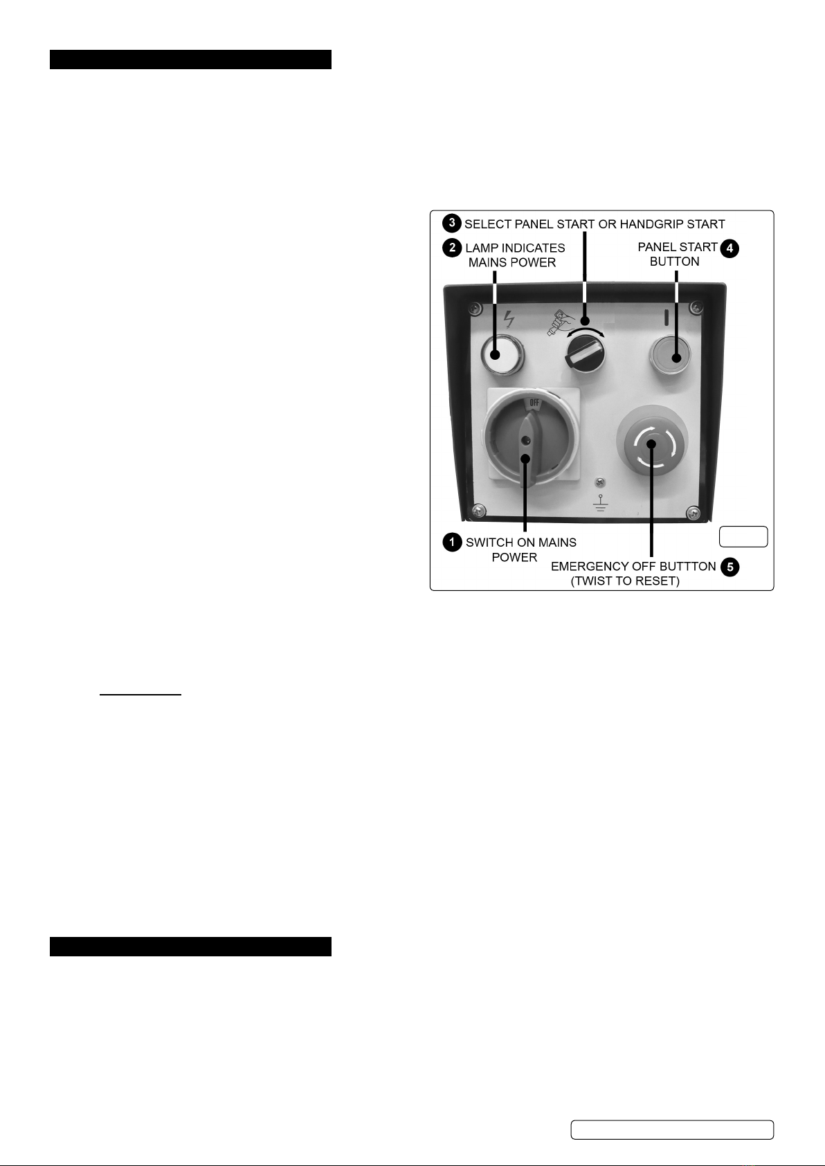
6.8. Turn on the mains power by turning the switch clockwise.
6.9. See (1) in Fig.14 above. The power lamp (2) will light.
6.10. Using switch (3) select whether the machine will turn on with the
6.11. Start Button (4) on the control panel or the handgrip switch. See (6)
in Fig.4.
6.12. Control panel start.
6.12.1. Start the saw by pressing the start button on the control panel.
6.12.2. Having previously set the rate of descent allow the blade to
descend slowly onto the workpiece by turning the hydraulic
tap to be in line with the cylinder. (If the blade should jam or
other problems occur immediately switch off the power by hitting the red emergency OFF button. Refer to the ‘Troubleshooting’ section
for common problems.
6.12.3. The coolant pump starts automatically when the machine is turned on and feeds coolant directly to the blade guides. The flow can be
regulated using the coolant feed tap as described in section 5.1.
6.12.4. When the cut is completed the machine will switch off automatically. Turn the mains power switch off and disconnect the saw from the
power supply, raise the blade and remove the workpiece. Wear gloves as the workpiece will be hot and have sharp edges.
6.12.5. Hand grip start. The hand grip is used in conjunction with the hydraulic damper to provide an extra degree of control, especially when
the blade first comes into contact with the workpiece. Furthermore the hand grip switch has to be held down to keep the blade running so
the machine can be stopped quickly by releasing the switch if problems occur such as the blade jamming.
6.12.6. In order to start the machine with the hand grip switch (See 4 in Fig.4) the selection switch on the control panel (See 3 in Fig.14) must be
turned to the hand grip symbol.
6.12.7. Set the blade rotating by holding down the handgrip switch. Having previously set the rate of descent allow the blade to move slowly
down towards the workpiece by turning the hydraulic tap to be in line with the cylinder. Allow the blade to rest lightly onto the workpiece
whilst making the initial cut. Keep the switch held down whilst the cut progresses. (If the blade should jam or other problems occur
release the hand grip switch immediately).
6.12.8. The coolant pump starts automatically when the machine is turned on and feeds coolant directly to the blade guides. The flow can be
regulated using the coolant feed tap as described in section 5.1.
6.12.9. When the cut is completed the machine will switch off automatically. Turn the mains power switch off and disconnect the saw from the
power supply, raise the blade and remove the workpiece.
WARNING! Never raise blade when machine is running .
WARNING! Wear gloves when handling sawn metal parts as the cutting process will have made them hot to touch and the cut
edges will be sharp.
WARNING! DO NOT rotate the bow when the machine is running.
7. MAINTENANCE
WARNING! Disconnect the bandsaw from the power source before servicing, changing accessories, or performing any other
maintenance.
7.12.1. Check the gearbox oil level on a monthly basis. This should be done with the bow raised to its highest position. Observe the oil level
in the sight glass on the side of the gearbox. If required, top up the oil by removing the filler bolt from the upper part of the gearbox just
below the motor. Change the oil every 6 months. The drain plug is at the bottom of the gearbox. Drain the gearbox with the bow in its
highest position.
7.12.2. Keep all surfaces clean and free from rust, slag, chips and coolant build-up.
8DO NOT use compressed air to clean bandsaw. Compressed air may force chips into the guide bearings and other critical areas of the
saw.
7.12.3. Use a small paint brush or parts cleaning brush to remove metal particles.
Fig.14
SM354CE | Issue:4 (H,F) 16/02/18
Original Language Version
© Jack Sealey Limited

7.12.4. Wipe saw down with a clean dry cloth and oil all unpainted surfaces with light machine oil.
7.12.5. Keep blade guides clean and free from metal chips.
7.12.6. Check guide bearings frequently to make sure they are properly adjusted and running freely.
7.12.7. Clean out the coolant tank at least twice a year.
WARNING! DO NOT attempt to to adjust the blade brush with the machine running. Adjust only when the machine is
disconnected from the power source.
8. TROUBLESHOOTING
PROBLEM CAUSE SOLUTION
Excessive
blade breakage
and/or teeth
ripping from the
blade.
1. Workpiece is loose in the vice. 1. Clamp the workpiece securely.
2. Incorrect feed. 2. Check bow weight and hydraulic feed.
3. Blade is too coarse. 3. See Section 4.9 for available blade types.
4. Workpiece material is too coarse. 4. Use the saw with a smaller tpi blade.
5. Incorrect blade tension. 5. Adjust blade tension so that it does not slip on the wheel.
6. Blade is in contact with workpiece before saw is started. 6. Place blade in contact with the workpiece only after the saw has started.
7. Blade is rubbing on the wheel flange. 7. If blade tracking needs adjustment, contact your local Sealey dealer.
8. Blade guides are misaligned. 8. If blade guides need adjustment, contact your local Sealey dealer.
9. Blade is too thick. 9. Use correct thickness blade.
10. Bad weld on blade. 10. Replace blade.
Premature
blade dulling.
1. Blade tpi is too high. 1. Replace with a smaller tpi blade.
2. Inadequate feed pressure. 2. Increase feed pressure by decreasing bow weight.
3. Hard spots or scale on the workpiece. 3. Increase feed pressure by decreasing bow weight.
4. Blade installed backwards. 4. Remove blade, twist inside out and reinstall.
5. Insufficient blade tension. 5. Increase blade tension.
5. Work hardened material especially stainless. 6. Increase feed pressure by decreasing bow weight.
Unusual wear
on side or back
of blade.
1. Blade guides are worn. 1. Replace blade guides.
2. Blade guides not properly adjusted. 2. Adjust as described in manual.
3. Blade guide brackets are loose. 3. Tighten blade guide brackets.
Motor
overheating.
1. Blade tension too high. 1. Reduce blade tension.
3. Blade too coarse or too fine. 3. Use a blade more suitable for the material being cut.
4. Gears need lubrication. 4. Top up gearbox.
5. Blade is binding in the cut. 5. Decrease feed.
Bad, crooked or
rough cuts.
1. Feed pressure too great. 1. Reduce feed pressure by increasing bow weight.
2. Blade guide bearings not properly adjusted. 2. Contact your Sealey dealer.
3. Inadequate blade tension. 3. Increase blade tension a little at a time.
4. Blade is dull. 4. Replace the blade.
6. Blade guide too far away from workpiece. 6. Move guide closer to workpiece.
7. Blade guide assembly is loose. 7. Tighten the guide assembly.
8. Blade is too coarse. 8. Use a finer blade.
Blade is
twisting.
1. Blade is binding in the cut. 1. Decrease feed pressure.
2. Blade tension is too high. 2. Decrease blade tension.
SM354CE | Issue:4 (H,F) 16/02/18
Original Language Version
© Jack Sealey Limited
Sealey Group, Kempson Way, Suffolk Business Park, Bury St Edmunds, Suffolk. IP32 7AR
01284 757500 01284 703534 sales@sealey.co.uk www.sealey.co.uk
Note: It is our policy to continually improve products and as such we reserve the right to alter data, specifications and component parts without prior
notice.
Important: No Liability is accepted for incorrect use of this product.
Warranty: Guarantee is 12 months from purchase date, proof of which is required for any claim.
ENVIRONMENT PROTECTION
Recycle unwanted materials instead of disposing of them as waste. All tools, accessories and packaging should be sorted, taken to
a recycling centre and disposed of in a manner which is compatible with the environment. When the product becomes completely
unserviceable and requires disposal, drain any fluids (if applicable) into approved containers and dispose of the product and fluids
according to local regulations.
WEEE REGULATIONS
Dispose of this product at the end of its working life in compliance with the EU Directive on Waste Electrical and Electronic Equipment
(WEEE). When the product is no longer required, it must be disposed of in an environmentally protective way. Contact your local solid
waste authority for recycling information.
Table of contents
Other Sealey Saw manuals

Sealey
Sealey TS10CZ User manual

Sealey
Sealey SM65.V2 User manual

Sealey
Sealey TS10P User manual

Sealey
Sealey CP108VRSBO User manual

Sealey
Sealey CP20VCS User manual

Sealey
Sealey Quality MACHINERY SM225 User manual

Sealey
Sealey MG3143 User manual

Sealey
Sealey SM1303 User manual

Sealey
Sealey TS1098 User manual

Sealey
Sealey SM63 User manual

Sealey
Sealey Siegen Tools S01005.V2 User manual

Sealey
Sealey SM35CE User manual

Sealey
Sealey SA342 User manual

Sealey
Sealey SRS850.V2 User manual

Sealey
Sealey SA34.V2 User manual

Sealey
Sealey sa347 User manual

Sealey
Sealey SRS850 User manual

Sealey
Sealey Quality machinery SM43.V3 User manual

Sealey
Sealey Quality MACHINERY SM2504 User manual

Sealey
Sealey SM1303.V2 User manual