Sealtech 430-R User manual

The Sealtech Leak Testing Method
Sealtech 430-R & 430-AL
For professional RV service technicians, one of the most difficult leaks to diagnose are water leaks
penetrating the exterior of the RV. The Number One cause of RV damage is water intrusion!
Any crack in the sealant or a penetration through any exterior surface is a potential leak
that can allow moisture to enter and begin its destructive action.
Oftentimes the leak will manifest itself at a location distant from its actual entry point
and can go unnoticed for an extended period of time. Rather than risk further damage
by flooding the exterior of the coach with water, the safe, sure way of detecting unintended
exterior breaches is to perform a pressurized leak test using the Sealtech 430-R & 430-AL.
This beneficial device permits the shop to offer the Sealtech method as a value-based aftermarket
service, as well as proving its worth during normal PDIs and troubleshooting tasks.
Using the Sealtech 430-R & 430-AL
Since the Sealtech concept uses a positive air pressure inside the
RV, it is necessary to prevent undue loss of pressure through
designed openings in the RV exterior such as doors, windows,
storage bays, vents, etc.
Preparing the RV for Testing
1. Tightly close all doors, windows and 14-inch roof vents,
including all access and bay doors. (One 14-inch roof vent will
be required to permit access air to the 430-R & 430-AL)
2. Plug the RV into shore power. (The 430-R & 430-AL require
a 120-volt AC power source inside the RV)
3. Turn off all fans, blowers and air conditioners.
4. Open the one 14-inch roof vent completely that you want to do your testing in & remove any
device covering that vent if any.
5. Remove interior vent garnish/trim, as well as the crank handle.
6. Remove the screen portion of the roof vent and reinstall the garnish/trim.
1
Setting Up the Sealtech 430R & 430-AL
2
Mechanical Set Up
1. Position the 430-R or 430-AL upper vent mating mechanism and secure it against the ceiling by
connecting the turnbuckle end clasps to the top lip of the roof vent and to the appropriate attachment
point in the mechanism cross member.
3
1
Reinstalling the vent trim/garnish provides ceiling protection and a quality seal.
2
All set-up functions are normally performed from inside the RV, unless equipped with a powered vent or vent cover.
3
Thicker roof dimensions will require the use of the supplied snap ring and possibly one or more chain links.

.
2
2. Orient the upper vent mating mechanism with one “J” cutout facing the front or rear of the RV,
depending on the desired facing direction of the bottom unit controls and gauge.
3. Tighten the turnbuckles until the upper mating mechanism seals completely against the ceiling.
Do not over tighten.
4. Attach one end of the short section of plastic
tubing to the upper side of the barbed bulkhead
fitting on the vent mating mechanism and allow
the other end of the tubing to simply lay on the
roof for ambient air access.
5. Position the cuff of the tubular duct over the
upper vent mating mechanism cuff. Align the duct
cuff pins with the “J” cutouts in the mechanism
cuff and secure by twist lock.
6. Position the bottom fan assembly on a level and
stable support such as the vehicle floor at a height
that permits a duct connection without undue
stretching of the duct.
7. Insert duct cuff into bottom fan assembly. Secure with twist lock.
8. Plug bottom fan assembly into an interior 120-volt AC receptacle.
9. Install pressure gauge on bottom fan assembly using the supplied wing screw.
10. Attach one end of the long section of plastic tubing to the barbed connection on the rear of the
pressure gauge and the other end to the barbed bulkhead fitting extending down from the upper vent
mating mechanism.
Pressure Set Up
Normal operating pressures will range from 0.3 to 0.6 water column inches, depending on the total
volume within the interior of the RV & the tightness of the envelope being tested.
1. With the entry door closed, turn on the 430-R or 430-AL and set it to the lowest RPM.
2. Gradually increase the RPM until the pressure remains steady between 0.3 to 0.6 water column
inches.
3. If the pressure measurement on the gauge remains at less than
0.4 inches of water column with the impeller running at maximum
RPM, additional sealing of the RV should be examined. A major
release of air pressure will usually be evident by inspecting all
exterior components on the RV. (Look for open or unsealed vents,
doors, or hatches indicated by outrushes of air. Check for a range hood
vent that is unlatched or dry sink traps)
.
3
4. Adjust the RPM to produce a pressure differential of 0.3 to 0.5 inches of water column.
4
5. Exit the RV and securely close the entry door.
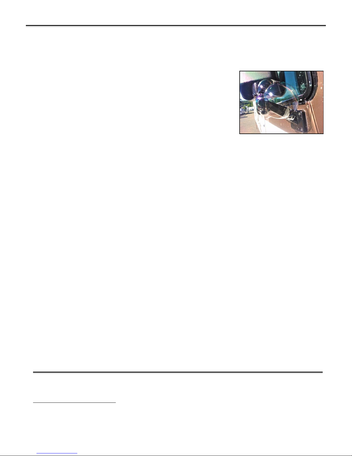
6. Spray a soapy solution onto all exterior areas where leaks are
likely to be found. Anything attached to the exterior of the RV,
including their respective sealants, should be examined. Visible
bubbles will indicate the source of a breach, but some judgment is
required. (As an example, Pittsburg-type seams will permit air escapement,
but not all resulting bubbles will be indicative of a leak due to the seam
overlap. However, where bubbles appear in a Pittsburg seam at a junction
with the leading edge of a window or other outer skin break, rain water
could be forced through by air pressure caused from traveling at highway
speeds)
7. Repair all sources of air leaks. If air pressure can escape, moisture can enter!
8. Re-test to verify all leaks have been reconciled.
9. Disconnect the 430-R or 430-AL and reassemble the 14-inch vent.
Special Notes
•Powered Roof Vents - When using this type of vent as the air source, it may be required to
utilize the included bridge adapter. Here’s how:
1. From within the RV, or from on the roof, (depending on your fan unit) remove the screws
securing the fan unit.
2. Remove the fan assembly as necessary and carefully set aside.
3. Position the bridge adapter across the top of the vent assembly.
4. From inside the RV, position the upper vent mating mechanism against the ceiling and
connect the turnbuckle end clasps to the bridge adapter rather than to the lip of the roof vent.
5. Test as normal once the upper vent mating mechanism is sealed against the ceiling.
6. After testing and repairing all leaks, reassemble the fan assembly.
•Supplies Required
1. Fresh water
2. Liquid dish soap or other surfactant liquid to mix with fresh potable water. (Approximately
1% mixture)
3. Handheld sprayer (fine nozzle) to project soapy solution onto the exterior surface of the RV.
4Larger leaks require a lower air pressure than small leaks. Pinhole-type leaks may require a test pressure up to 0.6 water
column inches.
This manual suits for next models
1
Table of contents


