Elektron ACCUMETER S 500 D User manual

Operating instructions GB
Battery tester
ACCUMETER S 500 D
324 43 /
ELEKTRON Bremen GmbH · Hinterm Sielhof 22 · D-28277 Bremen
Phone ++49 /42 /54 906-906 · Fax 54 90 6 9 · vertrieb@elektron-bremen.de · www.elektron-bremen.de
2
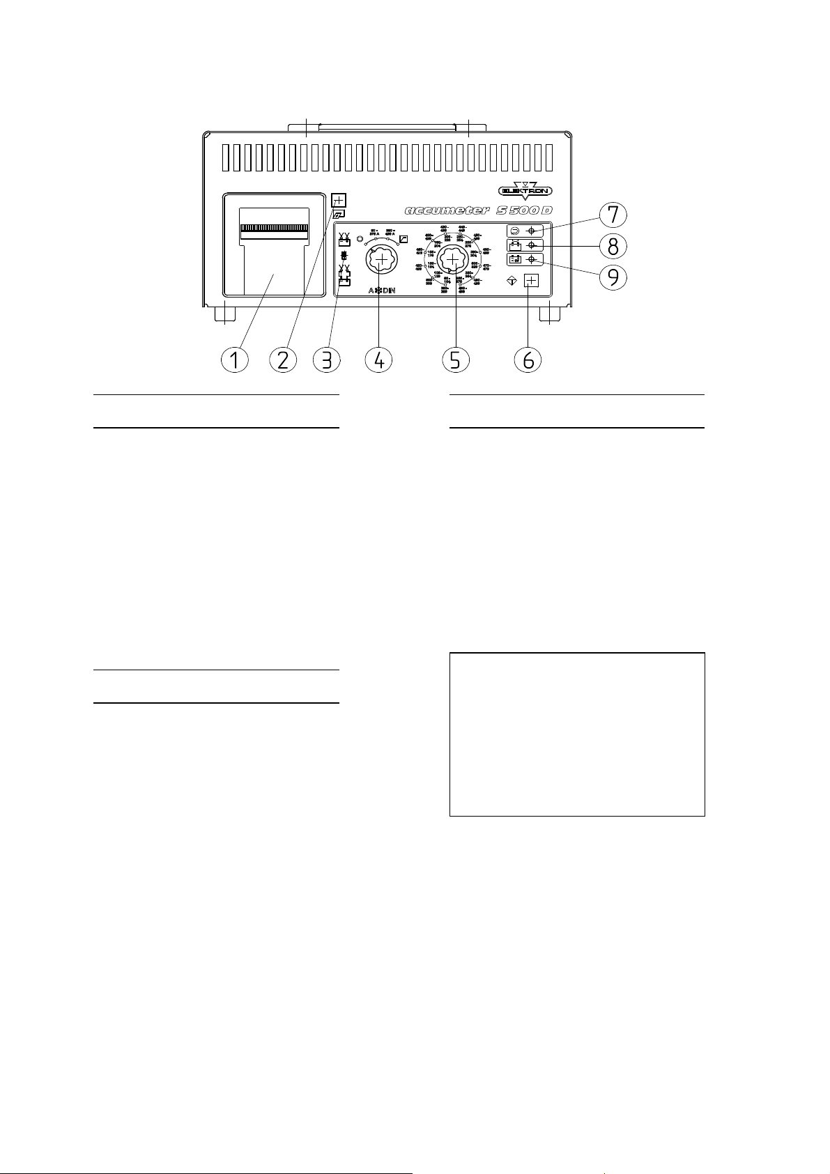
Legend 1.
0
Safety instructions
1 Printer
Attention! When testing the
battery,
2 Key paper advance e plosive gases can be created.
3 Slide switch Only test batteries in well
Battery tap to battery / at ventilated areas!
e ternal test point in engine Danger of e plosion due to
space formation of o yhydrogen gas.
4 ON/OFF function switch Avoid fire, naked flames and
5 Cold cranking current selection sparks!
switch Always wear safety glasses,
6 Start key protective gloves and protective
7 LED green (device operational) clothing!
8 LED red (device wrong polarity) Wash off acid drops on skin
9 LED red (battery test not possible) and/or clothes immediately.
ATTENTION
Table of contents
In the case of intense smell of
gas,
1.0 Safety instrucitons danger of imminent e plosion!
2.0 Device description
Do not switch device off!
3.0 Starting up
Do not remove testing clamps!
3.1 Battery test
Ventilate room immediately!
3.2 Regulator test
After sufficient ventilation,
switch
3.3 Battery test high current load off battery tester!
4.0 Printer
Protect battery tester from
5.0 Technical data dampness and wetness!
Ensure that the tester stands in a secure place.
Read instruction manual carefully before starting up the testing device.
Always use testing device in accordance with operating instructions.
The test clamps may not be removed during testing.
After the test has finished, turn switch (4) to 0 and then remove test clamps.

3
2.0 Device description
You can test 12 V starter batteries
from 80 - 499 ADIN
resp. 95 - 574 AIEC
resp. 36 - 855 AEN/SAE
= cold cranking current
using the battery tester. For test purposes, the batteries are loaded with a current which is equivalent
to the starting current of a car or lorry. The battery is judged under this load and the result of the
measurement is printed out on the printer.
The voltage supply for the device results from the starter battery to be checked.
3 LEDs show:
• device operational - LED green
• device connected in reverse - LED red
• battery voltage too small - LED red (battery test not possible, load battery)
Battery voltage has to be at least 6 V otherwise the unit will not operate.
Using the setting regulator test , it is possible to check that the regulator is working correctly.
3.0 Starting up
Take note of safety instructions!!
Observe of handling instructions battery manufacturer!!
3.1 Battery test
Find out cold cranking current of the battery in A according to DIN
(ADIN).
If the battery shows this value not in DIN but in IEC or EN/SAE, the value has to be changed by
means of the tables available on the unit. Set the cold cranking current with switch (5).
Set the measuring range 80 - 379 A resp. 380 - 499 A with switch (4).
Connect test clamps well and to the correct poles of the battery or connect to battery
support in the engine space.
Connect red clamp (+) to positive pole, black clamp (-) to negative pole.
Select connection point for test clamps using switch (3):
Position direct connection to battery.
Position connection to external testing point in engine space
Check whether cold cranking current stated on the battery is the same as the setting on the
battery tester.
Start test by pressing key (6)
• After the start key has been pressed, the green LED (7) "test started" lights up. The programme
runs automatically. The test result will be printed. The following test results can be printed:
"Starting capability very good"
"Starting capability good"
"Starting capability sufficient" - replace ment of battery recommended
"Starting capability bad" – replace battery

4
"Starting capability very bad" – replace battery
"Cannot be tested" - recharge battery and test again.
• LED (8) indicates whether the battery has been connected the wrong way round.
• LED (9) indicates "battery cannot be tested, battery has to be charged".
This indication appears if a printing is not possible.
If the starting capability is deemed to be "very good" or "good", you will not have any starting
difficulties in the winter either.
If the starting capability is deemed to be "sufficient", we recommend to replace the battery.
If the starting capability is deemed to be "bad", you will experience starting difficulties at low
temperatures and we urgently recommend replacement of battery.
If the starting capability is "very bad", you will always have starting difficulties, the battery must be
renewed.
Battery cannot be tested
• If the indicator (9) "cannot be tested" lights up, the battery must be charged first.
An empty battery cannot be distinguished from a faulty battery. After charging, the test is
repeated. If the indicator lights up again, the battery is faulty.
LED wrong polarity
• If, immediately after the test has been started, the indicator (8) "wrong polarity " lights up, the test
clamps have been connected to the wrong poles. If no display lights up, the contact between the
load clamps and the battery poles should be checked or the voltage of the 2V battery in < 7V in
the unloaded state . The battery must be charged first in this case.
End of test
• After max. 20s the test has finished. The result is printed (the test can be repeated by starting it
again once the printer has finished printing).
ATTENTION! Before removing the test clamps, switch the device off using the turn switch (4).
3.2 Regulator test
Set switch (4) to 0.
Ensure good contact and correct polarity between test clamps and battery poles or external test
point in the engine space.
Start engine.
Set switch (4) to "regulator test" .
Operate start key (6).
• The green LED (7) "test running" lights up". The vehicle battery is charged by the dynamo. As
soon as the voltage of the battery has stabilised, in the case of an intact battery and dynamo in
approx. 4 minutes, the test result is printed out. The print-out shows "regulator normal".
If the battery voltage does not stabilise itself within 4 minutes, the device terminates the test. The
print-out reads "regulator test not possible". In this case, the vehicle's electrics, the battery and the
dynamo should be checked.
The print-out "regulator too low" is a result of a faulty battery or a faulty regulator. The print-out
"regulator too high" indicates that the regulator voltage is too high, the battery is continuously
being overcharged: significant water loss!
ATTENTION! Before the test clamps are removed, switch the device off using the rotary switch
(4).

5
3.3 Battery test - high current load
Recognising battery guarantee damage:
Manufacturing faults can be recognised using the testing device with a high current load on the
battery. Typical guarantee cases are fine contacts and cold soldering points in the cells which do
not occur until after the battery is being used. Under high current load, these faults cause the
following:
Fine contacts
Pearly gas in the faulty cell.
Cold soldering spots
Local boiling of the faulty cell with unpleasant development of sulphur odour.
Course of test
ATTENTION! Only test battery after it has been removed from the car.
Ensure good contact and correct polarity between test clamps and poles.
Switch rotary switch (4) to range of cold cranking current ADIN
(80 - 379 A resp. 380 - 499 A). For testing purposes the cell bungs are removed and whilst the
load is being applied, the behaviour of the cells is observed.
ATTENTION! Do not bring your face too close to the battery. It is very important to observe safety
instructions (see .0).
Press the start key (6) until the faulty cell shows the typical reactions. The gas formation or boiling of
the cell begins after approx. 20 to 30 s. The permanent load application is limited to 30 s and
switches off automatically. The load can be applied again by briefly letting go of the start key (6)
and then pressing it again.
ATTENTION! Before removing test clamps turn off the tester by using rotary switch (4).
ATTENTION! Do not overheat device. Wait for it to cool down.
ATTENTION! As large amounts of gas can be formed during this test, this test may only be carried
out in well ventilated rooms.
4.0 Printer
The printer is equipped with a replaceable paper roll and a colour tape cartridge (available from
retailer).
Changing the paper roll
Remove clear hood
Remove axle of the paper roll
Push new paper roll onto axle and place into depression for paper roll in the printer (end of paper
to the top, paper runs from behind).
Put printer into paper feed mode.
ATTENTION! Device must be connected to a battery!
Set switch (4) to position "battery test" (range of cold cranking current 80 - 397 A).
Press and hold the key "paper feed" (2).
Press (6) key "Start"
• The green LED (7) flashes.
Release key (2) and (6)
Feed the end of the paper into the paper shaft (the paper shaft is situated behind the colour tape).
The paper must be fed to the stop position.

6
Press key "paper feed " (2) until the paper has been pushed out by approx. 3 cm. Feed the paper
through the slot in the cover and close the cover.
Press the "Start" key (6).
• Green LED extinguishes.
Turn off switch (4).
Remove clamps from battery.
Change colour tape
The colour tape cartridge has "Push" engraved on it at one side. By pushing the cartridge gently
at this point, it can be levered out and then taken out from the front.
Putting in a colour tape cartridge:
Before putting another cartridge in, tension the colour tape with the rotary button. Now the
cartridge can be put into the printer. In doing so the free part of the colour tape is fed through the
slot through which the paper would be normally fed through too.
ATTENTION! It is not permitted to pull the paper hanging out of the printer by hand as it could be
damaged. It is also not permitted to pull the paper back through the printer by hand.
5.0 Technical data
ACCUMETER Type S 500 D
Battery voltage: 2 V
Load current range
(80 - 379 A): 250 A
Load current range
(380 - 499 A): 500 A
Controlling system:
Electronic testing device with LED displays and print-out of the test results via integrated printer.
Cooling type: Self-cooling
System
of protection:drip-water protection IP 2
Measurement
(H / W / D): 2 0 x 365 x 230 mm
Weight: 8,0 kg
Table of contents
Popular Test Equipment manuals by other brands


Baur
Baur KSG 200 A user manual

Hangzhou Ruideng Technology
Hangzhou Ruideng Technology AT34 instructions

Tempo Fitness
Tempo Fitness 77HP instruction manual

Dukane Seacom
Dukane Seacom TS500 Technical manual

Reed Instruments
Reed Instruments R5500 instruction manual

trendmedic
trendmedic TM-2000 Operation manual