Sealy POWER PRODUCTS YG10.48 User manual

Thank you for purchasing a Sealey product. Manufactured to a high standard this product will, if used according to these instructions
and properly maintained, give you years of trouble free performance.
1. SAFETY INSTRUCTIONS
IMPORTANT: PLEASE READ THESE INSTRUCTIONS CAREFULLY. NOTE THE SAFE OPERATIONAL REQUIREMENTS, WARNINGS AND
CAUTIONS. USE THIS PRODUCT CORRECTLY AND WITH CARE FOR THE PURPOSE FOR WHICH IT IS INTENDED. FAILURE TO DO SO MAY
CAUSE DAMAGE AND/OR PERSONAL INJURY AND WILL INVALIDATE THE WARRANTY. PLEASE KEEP INSTRUCTIONS SAFE FOR FUTURE USE.
INSTRUCTIONS FOR:
4800W 110/230V DIESEL
GENERATOR
Model: YG10.48
YG10.48 - 1 - 070703
1.1. GENERATOR SAFETY
pWARNING! Ensure any Health & Safety, Government and local authority regulations are adhered to when using this equipment.
3Familiarise yourself with the application, limitations and hazards of the generator.
3Maintain the generator in good condition (use an authorised service agent). Replace or repair damaged parts. Use genuine parts only.
Unauthorised parts may be dangerous and will invalidate the warranty.
3This generator is designed and manufactured for specific applications. Do not attempt to modify the unit or use it for any application for
which it is not designed. If you have any questions regarding the application of the unit please contact your local Sealey dealer.
pWARNING! DO NOT exceed the Wattage/Amperage capacity of the generator. Add rated wattage of all equipment intended for connection
at any one time - the total must not exceed the rated wattage of generator (see specification). In most cases the wattage of electrical
equipment can be found on the nameplate. If the nameplate gives only voltage and amperage, multiply the two to give rated wattage.
p
p
WARNING! Generator exhaust gases contain deadly carbon monoxide which must not be inhaled. Always allow sufficient ventilation.
p
p
WARNING! If you decide to use an Earth Leakage Circuit Breaker (also referred to as an RCD or Ground Fault Circuit Interrupter),
it is imperative that the neutral end of the power winding is connected to the frame of the generator set and that the earth lug on the
frame is connected with a low impedance connector to the local earth via an earth spike or local protective earth conductor. This
connection should only be attempted by a qualified electrician, after first having consulted your local dealer.
s
s
DANGER! This generator is designed for outdoor use only. To use the generator inside any building or enclosure, including the
generator compartment of a caravan, may result in fire or an explosion. No user performed modifications, including venting of
the exhaust and/or cooling ventilation, will eliminate the danger.
s
s
DANGER! If this unit is used for back-up power in the event of a commercial power failure, the following steps must be taken.
Before connecting the generator to the electrical system, open the main circuit breaker to isolate the generator and system from
the commercial electric supply. Failure to do this may result in damage to the generator and may result in serious injury or fatality,
due to a back-feed of electrical energy.
s
s
DANGER! The generator produces a very powerful voltage that can cause a severe electrical shock. Avoid contact with bare
wires, terminals etc. Never allow any unqualified person to operate or service the generator.
p
p
WARNING! Diesel is flammable and the vapour is explosive. Do not permit smoking, naked flames, sparks or heat in the vicinity
while handling fuel. Avoid spilling diesel onto a hot engine. Comply with all laws regulating storage and handling of fuels.
p
p
WARNING! NEVER refuel when the engine is running or when the engine is hot. Allow cool down time.
3Operate the generator only on level surfaces (maximum allowable tilt is 10º) and where it will not be exposed to excessive moisture, dirt or
corrosive vapours or be in the proximity of combustible material (flammable liquids, solids or gases).
3Remove ill fitting clothing, ties, watches, rings and other loose jewellery and contain long hair. Wear appropriate protectiveclothing.
3Keep non-essential persons away from the work area.
p
p
WARNING! Never start or stop the generator while electrical loads are connected and switched on. Start the engine, let it
stabilise, then connect the electrical load. To stop engine, disconnect the electrical load and let engine stabilise before switching off.
p
p
WARNING! Do not use worn, bare, frayed or otherwise damaged electrical cables with the generator. To do so may result in electric shock.
7DO NOT use the generator for any purpose other than that for which it is designed.
7DO NOT operate the generator if any parts are missing or damaged, as this may cause failure and/or personal injury.
7DO NOT over-fill fuel tank. Always leave room for fuel to expand.
7DO NOT operate in the rain.
s
s
DANGER! Do not tamper with the engine governed speed setting. Higher operating speeds are dangerous and increase the risk
of personal injury and/or equipment damage. The generator supplies the correct rated frequencies and voltage only when
running at the correct governed speed. Incorrect frequency and/or voltage can damage some connected electrical loads.
Operating at excessively low speeds may result in shortened engine life. Over-speeding will invalidate the warranty.
7DO NOT operate the generator when you are tired or under the influence of alcohol, drugs or intoxicating medication.
7DO NOT store generator with fuel in tank where fuel vapours might reach an open flame or spark.
1.2. BATTERY SAFETY
DANGER! BE AWARE, LEAD-ACID BATTERIES GENERATE EXPLOSIVE GASES DURING NORMAL BATTERY OPERATION
AND THE ELECTROLYTE IS CORROSIVE. FOR THESE REASONS, IT IS VERY IMPORTANT TO READ AND FOLLOW
THESE INSTRUCTIONS CAREFULLY.
Follow these instructions and those of the maker of any equipment you intend to use in the vicinity of the battery. Remember to
review warning marks on all products and on engines.
3When working with, or near, a lead-acid battery ensure that there is another person within hearing range of your
voice and close enough to come to your aid should a problem arise.
3Wear safety eye protection and protective clothing. Avoid touching eyes while working near battery.
3Have fresh water and soap nearby in case battery acid contacts skin, clothing, or eyes.
3Wash immediately with soap and water if battery acid contacts skin or clothing. If acid enters eye, flush eye immediately with cool, clean
running water for at least 15 minutes and seek immediate medical attention.
3Remove personal metallic items such as rings, bracelets, necklaces and watches. A lead-acid battery can produce a short-circuit current
high enough to weld a ring or the like to metal, which would cause severe burns.
7DO NOT smoke or allow a spark or flame in the vicinity of the battery or engine.
pWARNING! DO NOT drop metal tools on, or otherwise allow them to touch, both battery terminals. The resulting short circuit could cause an explosion.
7DO NOT cross connect power leads from starter to the battery. Ensure positive (+) (RED) is to positive and negative (-) BLACK is to negative.
,

3. OPERATING INSTRUCTIONS
p
p
WARNING! Before use, ensure that you read, understand and apply with the safety instructions in this document. Ensure that
you fully understand the application, limitations and hazards of the generator.
p
p
WARNING! Never connect the generating set earth lead to pipes. Pipes may carry flammable substances such as gas or
domestic fuel and there is a risk of fire or explosion in the event of a short circuit.
p
p
WARNING! Never run the engine without the air filter fitted.
p
p
WARNING! If the generator is being used after storage of more than 30 days, remove the desiccant bags from the alternator
and the plastic tape from the air inlet and outlet ports - see 5.7.
s
s
IMPORTANT! The generator must not be more than 10O(13%) from the horizontal in any plane.
3.1. EARTHING
3.1.1. The generator must be earthed every time it is used, to reduce the chance of electric shock. To do this, use a 10mm² copper wire and
bolt it to the generator earth point (fig. 1.1). Connect the other end to an earthing rod which has been driven into the ground to a
depth of one metre. This earthing connection will also dissipate any static electricity generated by the electrical equipment.
3.2. PRE START-UP
3.2.1. The battery is supplied charged but dry and the electrolyte (sulphuric acid) must be added before first use. Ensure that you
have read and understood the battery safety instructions in Section 1 and then follow the manufacturers instructions
supplied with the battery.
3.2.2. Once the electrolyte has been added, clamp the battery to the battery plate on the generator frame, as shown in fig. 1.2, and connect
the positive (red) and negative (black) wires to the positive and negative battery terminals respectively.
p
p
WARNING! Check the engine oil level before each start-up. Only use an approved oil and NEVER operate the engine with insufficient oil.
3.2.3. Ensure that the generator set is on a flat horizontal surface and that the engine is not running and is cold.
3.2.4. Unscrew the oil filler/dipstick (fig. 2.D) and wipe the dipstick clean.
3.2.5. Insert the dipstick into the filler neck but DO NOT screw it in.
3.2.6. Remove the dipstick and check the oil level. It should be between the two lines (fig. 3) - never below the lower and never above the
higher. If the level is too low (below the lower line), top-up the oil and recheck the level.
3.2.7. Replace the dipstick and screw in.
3.2.8. Turn on the fuel valve (located behind air filter/fuel filter access panel, see fig. 9).
3.3. FILLING WITH FUEL
p
p
WARNING! NEVER refuel when the engine is running or when the engine is hot.
Allow cool down time.
p
p
WARNING! Diesel is flammable and the vapour is explosive.
p
p
WARNING! Never use an oil/fuel mixture or any polluted fuel. Fuel substitutes or
additives are not recommended.
3.3.1. Ensure all electrical loads are disconnected.
3.3.2. Ensure the area around the fuel tank filler is clean.
3.3.3. Remove the fuel tank filler cap, check the level of the fuel and refill if necessary.
3.3.4. Do not over-fill the fuel tank, always leave room for the fuel to expand.
YG10.48 - 1 - 070703
fig. 1
fig. 2
Power Unit . . . . . . . . . . . . . . . . . . . . . . . . . 10hp
Motor Type . . . . . . . . . . . . . . . . . . Yanmar L100
Output: . . . . . . . . . . . . . . . . . . 230V/110V - 50hz
Current Rating: . . . . . . . . . . . . . . . . 20.1A/43.6A
Continuous Power Rating: . . . . . . . . . . . . 4800W
Fuel . . . . . . . . . . . . . . . . . . . Diesel, Cetane >45
Fuel Tank Capacity . . . . . . . . . . . . . . . . . . . 26ltr
Oil Specification . . . . . . APICC/CD-MILL.2104C
Oil Viscosity . . . . . . . . . . . 20W40 (-10 to +40OC)
5W30 (-30 to -10OC)
Oil Capacity . . . . . . . . . . . . . . . . . . . . . . . 1.65ltr
Running Time: . . . . . . . . . . . . . . . . . . . . . 19.6hr
Noise Rating: . . . . . . . . . . . . . . . . . . . . . 99LWA
Dry Weight:. . . . . . . . . . . . . . . . . . . . . . . . 140kg
2. INTRODUCTION & SPECIFICATION
Powerful Yanmar L100 diesel engine produces 10hp. Electric starter unit with dual voltage high quality alternator. Highly efficient engine runs
for 19.6hrs on one tank of diesel. Suitable for site work and outdoor use.
Complies with EC2000/14 noise regulations. Fitted with 16A - 230V, 16A - 110V, 32A - 230V and 16A - 110V power outlets with safety trip.
Optional wheel kit available - order GEN/KIT2.
SPECIFICATION
fig. 4
fig. 3

4.2. ENGINE OIL
p
p
WARNING! Exposing the skin for long periods and repeatedly to used engine oil can cause cancer. It is obvious that the risk
is relatively low unless oil is handled every day and for a long period of time. However, it is recommended to carefully wash
hands immediately after handling used oil.
Drain the engine oil when the engine is warm to ensure quick and complete drainage.
4.2.1. Remove the cover plate, fig. 4.C.
4.2.2. Place a suitable container below the drain plug (fig. 7.1). Remove the dipstick and the oil
drain plug and washer and let the oil drain completely.
4.2.3. Refit the oil drain plug and washer and the cover plate.
4.2.4. Fill the sump with new oil, through the dipstick hole, up to the dipstick upper level (see 3.2.4-7.).
4.3. OIL STRAINER
Important! Before removing the oil filter ensure that the oil has been drained (para. 4.2.).
4.3.1. Remove the side panel (fig. 4.A).
4.3.2. Remove the screw from the strainer end (fig. 7.2) and pull out the strainer.
4.3.3. Rinse the oil strainer in clean petrol or diesel and then thoroughly dry it.
4.3.4. Replace the strainer and retaining screw.
Important! DO NOT forget to fill the sump with fresh oil (para. 4.2.).
4.3.5. Refit the dipstick and side panel.
Notes: 1 Service more often if used in dusty conditions. 2 These services must be carried out by an authorised Service Agent.
YG10.48 - 1 - 070703
4. MAINTENANCE
4.1. GENERAL MAINTENANCE SCHEDULE
p
p
WARNING! All maintenance work is carried out when the engine is not running. If the engine must
be run, ensure that the working area is well ventilated. Exhaust gases contain carbon monoxide and
exposure to this toxic gas can cause loss of consciousness and death.
p
p
WARNING! If the engine has just been running, the exhaust system will be very hot, take care not
to touch it.
3The oil, oil filter, air filter and fuel filter must be serviced regularly. All other maintenance must be carried out by your local Sealey service agent.
3Before carrying out any maintenance disconnect the negative cable from the battery terminal to prevent accidental starting or shorting.
Maintenance Period First month 3 months 6 months 1 year
Operation or 20 hours or 100 hours or 500 hours or 1000 hours
Drain and clean the fuel tank l
Change the engine oil ll
Check and adjust the valve clearances (2) ll
Clean the generating set l
Check battery l
Clean the oil strainer l
Replace the air filter (1) l
Check injection system (2) l
Check cylinder head bolt torque (2) l
Replace the fuel filter l
Replace piston rings (2) l
Reseat the valves (2) l
3.4. STARTING THE GENERATOR
p
p
WARNING! The output sockets will be live once the engine has started.
3.4.1. Ensure that you have performed all actions in paras. 3.1., 3.2. and 3.3.
3.4.2. Open the engine hatch (fig. 4.B) and move the fuel control (fig. 2.B) to the Run position.
3.4.3. Insert the key (fig. 2.A) and turn it clockwise to operate the starter motor.
3.4.4. As soon as the engine starts release the key.
If the engine fails to start do not operate the starter motor for more than 5 seconds. Leave for 15 seconds and then try again. If it still will
not start refer to Troubleshooting section. If necessary contact your authorised Sealey service agent.
3.4.5. Once the engine is running close the engine hatch, engaging top and bottom latches.
Note: There is a decompression lever on the top of the engine (fig. 5) which is only used on recoil start models. It is not used on this electric
start model and must remain in the vertical position at all times.
3.5. USING THE GENERATOR
p
p
WARNING! Do not exceed the wattage capacity of the generator.
3.5.1. Allow the engine to warm up (approximately 3 minutes).
3.5.2. Select the required voltage output using the voltage selector switch (fig. 6).
3.5.3. Connect the equipment to the appropriate generator socket.
3.5.4. Always observe the safety instructions of the equipment being used.
3.5.5. Carry out the following checks whilst the generator is in use:
Is there any vibration or abnormal noise?
Is the engine not running smoothly?
What colour is the exhaust gas (it should be clear once the engine is warm)?
3.5.6. If you notice anything wrong, stop the generator (para. 3.6.) and contact your local servicing agent.
3.6. STOPPING THE GENERATOR
3.6.1. Disconnect the electrical load.
3.6.2. Allow the engine to run unloaded for 3 minutes and then open the engine hatch (fig. 4.B).
3.6.3. Stop the engine by moving the red lever (fig. 2.C) to the Stop position.
3.6.4. Turn off the key, remove it and close the hatch.
fig. 7
fig. 6
fig. 5

YG10.48 - 1 - 070703
5. STORAGE FOR MORE THAN 30 DAYS
If you store the generator for more than 30 days it is essential to protect the fuel system by draining all the fuel.
p
p
WARNING! Diesel is flammable and the vapour is explosive. Do not permit smoking, naked flames, sparks or heat in the vicinity
while handling fuel. Avoid spilling fuel onto a hot engine. Comply with all laws regulating storage and handling of fuels.
5.1. CLEAN
5.1.1. Remove debris and dust accumulations from the generating set surfaces.
5.2. DRAINING THE FUEL
5.2.1. Siphon the fuel from the fuel tank into an approved container.
5.2.2. Start the engine and allow it to run until it stops from lack of fuel.
5.3. CHANGE THE ENGINE OIL
5.3.1 To change the engine oil, refer to the instructions in paragraph 4.2.
5.4. ALTERNATOR PROTECTION
5.4.1. Remove the end cover and put desiccant bags inside the alternator.
5.4.2. Refit the alternator end cover.
5.4.3. Cover the alternator air inlets and outlets with plastic adhesive tape.
5.5. STORAGE
5.5.1. Store the generator in a safe, dry, childproof area, free of excessive humidity and dust.
4.4. AIR FILTER
Note: If the air filter is dirty, air flow to the engine will be restricted causing smoky exhaust, reduced power and increased fuel consumption.
p
p
WARNING! Never try to clean the element. Always replace it.
4.4.1. Remove the access panel (fig. 8).
4.4.2. Unscrew the wing nut (fig. 9.2) and remove the air filter cover (fig. 9.1). Lift out the filter element (fig. 9.3).
4.4.3. Fit the new element, replace cover and retain with the wing nut and washer.
4.4.4. Replace the access cover.
4.5. FUEL FILTER
p
p
WARNING! Never try to clean the fuel filter. Always replace it.
4.5.1. Remove the access panel (fig. 8).
4.5.2. Turn off the fuel valve (see fig. 9).
4.5.3. Disconnect the fuel lines from the fuel filter (fig. 9.4).
4.5.4. Fit the new filter and replace the access cover.
4.6. CLEANING THE GENERATING SET
4.6.1. Clean the generating set using a brush and cloth (water jet cleaning is not recommended). Clean the alternator air inlets and the battery casing.
4.6.2. Make the most of this cleaning by checking the condition of the generating set and change any defective or worn parts.
4.7. BATTERY
4.7.1. Check that the battery case and the terminals are clean.
Note: Since the battery is Maintenance Free no other action is required.
fig. 9
fig. 8
6. TROUBLESHOOTING
PROBLEM CAUSE ACTION
Engine will not start. Fuel tap not turned on. Turn fuel on.
No fuel in tank. Fill fuel tank.
Fuel control not in Run position. Set control correctly.
Valve lifter applied. Return lever to the run position (vertical).
Air or fuel filter blocked. Replace filter.
Engine runs roughly. Air or fuel filter partially blocked. Replace filter.
Dirty/stale fuel. Drain and replace fuel.
Injection system fault. Contact Sealey service agent.
No electrical output. Voltage selector switch
incorrectly positioned. Select the correct voltage.
Circuit breaker tripped. Re-set circuit breaker.

Declaration of Conformity We, the sole importer into the UK, declare that the product listed here
is in conformity with the following standards and directives.
The construction file for this product is held by the Manufacturer and may be inspected, by a national
authority, upon request to Jack Sealey Ltd.
For Jack Sealey Ltd. Sole importer into the UK of Sealey Power Products.
8th August 2003
DIESEL GENERATOR
Model: YG10.48
98/37/EC Machinery Directive
73/23/EEC Low Voltage Directive
89/336/EEC EMC Directive
93/68/EEC CE Marking Directive
Signed by Mark Sweetman
NOTE: It is our policy to continually improve products and as such we reserve the right to alter data, specifications and component parts without prior notice.
IMPORTANT: No liability is accepted for incorrect use of product.
WARRANTY: Guarantee is 12 months from purchase date, proof of which will be required for any claim.
INFORMATION: For a copy of our latest catalogue and promotions call us on 01284 757525 and leave your full name and address, including postcode.
CURRENT (A) CABLE LENGTH
0-50 metres 51-100 metres 101-150 metres
6 1.5mm² 1.5mm² 2.5mm²
8 1.5mm² 2.5mm² 4.0mm²
10 2.5mm² 4.0mm² 6.0mm²
12 2.5mm² 6.0mm² 10.0mm²
16 2.5mm² 10.0mm² 10.0mm²
18 4.0mm² 10.0mm² 10.0mm²
24 4.0mm² 10.0mm² 16.0mm²
26 6.0mm² 16.0mm² 16.0mm²
28 6.0mm² 16.0mm² 16.0mm²
7. CABLE SIZES
8. SERVICE PARTS
9. DECLARATION OF CONFORMITY
YG10.48 - 1 - 070703
The table below shows the recommended cable size (core section) for given current and cable length.
Sole UK Distributor,
Sealey Group,
Bury St. Edmunds, Suffolk.
01284 757500 01284 703534 sales@sealey.co.uk www.sealey.co.uk
e-mail Web
Part Number Description
114650-12590 Air Filter Element
30501007901 Fuel Filter
114250-35110 Oil Strainer & O-ring
24341-000224 O-ring, Oil Strainer
714650-53100 Injector Assembly
114350-11470 Spacer, Injector
114250-11460 Gasket, Injector
114699-01760 Dipstick & O-ring
Part Number Description
114299-01950 O-ring, Dipstick
330400494 Fuel Filler Cap
31809000201 Fuel Tap
31101000401 Fuel Gauge
114650-11311 Gasket, Rocker Cover
22190-160002 Washer, Oil Drain Plug
30702063601 Battery
30702024401 Battery Electrolyte
Popular Portable Generator manuals by other brands
KUMATSUGEN
KUMATSUGEN GB1400i owner's manual
Agilent Technologies
Agilent Technologies N5161A Service guide
Fischer Panda
Fischer Panda Panda PMS-HD 12-4KU manual
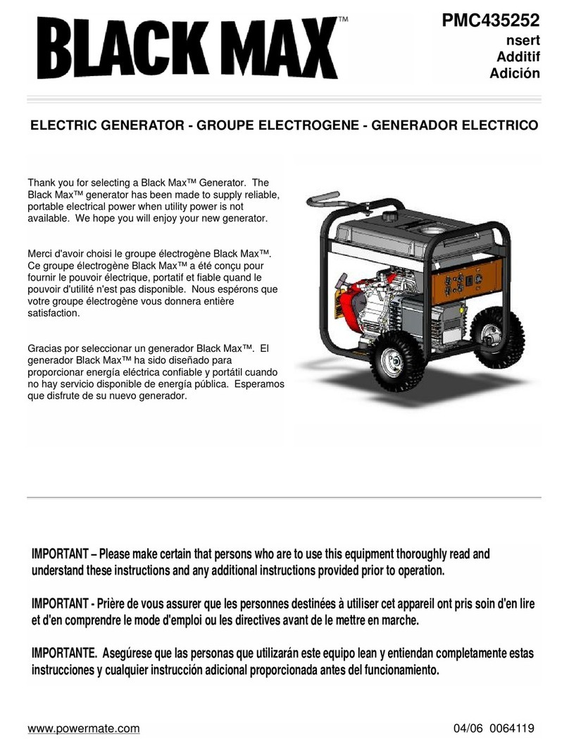
Powermate
Powermate Black Max PMC435252 user manual

Agilent Technologies
Agilent Technologies E4423B Installation notes
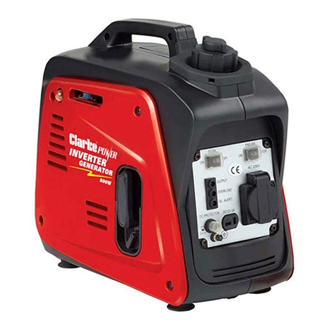
Clarke
Clarke IG950C Operation & maintenance instructions

DUROMAX
DUROMAX DUAL FUEL XP7500DX user manual
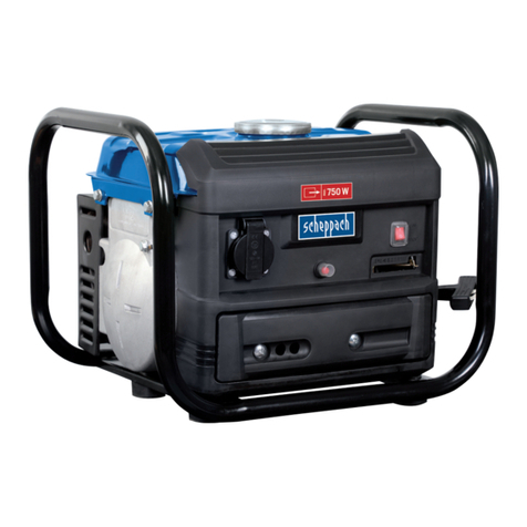
Scheppach
Scheppach SG1000 Translation of original instruction manual
Hokuetsu
Hokuetsu AIRMAN SDG220S-8E1 instruction manual
Honeywell
Honeywell HW7500E - Portable Generator NOT Specification sheet
Mecc Alte
Mecc Alte NPE32 Series user manual
Onan
Onan KVC Series installation manual
