Sears Kenmore 122.16648901 User manual

Use and Care Guide
®
Li id P G G ill
Li
qu
id
P
ropane
G
as
G
r
ill
Sears Model No. 122.16648901
Kmart Item No. 640-82960819-9
Sft
•
S
a
f
e
t
y
• Parts
• Use and Care
• Assembly
Grill Information Center
Missin
g
Parts? Assembl
y
Q
uestions?
This Grill is for Outdoor Use Only
•Read and follow all Safety, Assembly,
and Use and Care Instructions in this Guide
before assembling and cooking with this grill.
•Failure to follow all instructions in this Use and Care
Guide may lead to fire or explosion, which could result
gyQ
Operation Problems? Before returning
grill to store, call 1-800-913-8999.
Tools needed for assembly:
Guide
may
lead
to
fire
or
explosion,
which
could
result
in property damage, personal injury or death. Adjustable wrench (not provided)
Screwdriver (not provided)
7/16” Combination wrench (not provided)
SAVE THESE INSTRUCTIONS !
See our extensive assortment of outdoor living products on
-
line at
See
our
extensive
assortment
of
outdoor
living
products
on
-
line
at
www.sears.com and www. kmart.com
Sears Brands Management Corporation, Hoffman Estates, IL 60179 U.S.A.
© 2010 Sears Brands, LLC Printed in China

Warranty-------------------------------------------------1
Safety Precautions--------------------------------1~-3
Parts Diagram -----------------------------------------4
Parts List
5
WARNING
Combustion by products produced when using
this product contain chemicals known to the
State of California to cause cancer, birth defects,
Precautions
!
Table of Contents
Parts
List
------------------------------------------------
5
Assembly Instructions----------------------------6~9
Lighting Instructions----------------------------10~11
Light Operation Instruction--------------------12-13
Cleaning and Maintenance-------------------14~15
Troubleshooting--------------------------------------15
Cooking Instruction----------------------------------16
Cooking Chart----------------------------------------17
or other reproductive harm.
WARNING
Failure to comply with these instructions could
result in a fire or explosion that could cause
serious bodily injury, death, or property damage.
WARNING
!
!
One-Year Full Warranty on Kenmore Grill
If thi ill f il d t d f ti t i l
WARNING
Your grill will get very hot. Never lean over the
cooking area while using your grill. Do not touch
cooking surfaces, grill housing, lid or any other
grill parts while the grill is in operation, or until the
gas grill has cooled down after use.
Failure to comply with these instructions may
result in serious bodily injury.
!
Kenmore Grill Warranty
If
thi
s gr
ill
f
a
il
s
d
ue
t
o a
d
e
f
ec
ti
ng ma
t
er
i
a
l
or
workmanship within one year from the date of
purchase, call 1-800-4-MY-HOME to arrange for
free repair (or replacement if repair proves
impossible).
Ten-Year Limited Warranty on Stainless Steel
Burners
For ten years from the date of purchase any
WARNING
1. Do not store or use gasoline or
other flammable liquids or vapors in
the vicinity of this or any other
appliance.
2
A
LP
li d t
tdf
!
For
ten
years
from
the
date
of
purchase
,
any
stainless steel burner that rusts through will be
replaced free of charge. After the first year from
the date of purchase, you pay for labor if you
wish to have it installed.
All warranty coverage excludes ignitor batteries
and grill part paint loss, discoloration or rusting,
which are either expendable parts that can wear
2
.
A
n
LP
cy
li
n
d
er no
t
connec
t
e
d
f
or
use shall not be stored in the vicinity
of this or any other appliance.
DANGER
If you smell gas:
!
which
are
either
expendable
parts
that
can
wear
out from normal use within the warranty period,
or are conditions that can be the result or normal
use, accident or improper maintenance,
All warranty coverage is void if this grill is ever
used for commercial or rental purposes.
All warranty coverage applies only if this grill is
If
you
smell
gas:
1. Shut off gas to the appliance.
2. Extinguish any open flame.
3. Open lid.
4. If the odor continues, keep away
from the appliance and immediately
call your gas supplier or your fire
department
All
warranty
coverage
applies
only
if
this
grill
is
used in the United States.
This warranty gives you specific legal rights, and
you may have other right which vary from state to
state.
Sears Brands Management Corporation,
Hoffman Estates
,
IL 60179 U.S.A.
department
.
Grill Installation Codes
The installation must conform with local codes or,
in the absence of local codes, with either the
national fuel gas code, ANSI Z 223.1/NFPA S4,
Natural gas and propane installation code, CSA
B149.1, or
p
ro
p
ane stora
g
e and handlin
g
code,
,
pp g g
B149.2, or the standard for Recreational vehicles,
ANSI A 119.2, and CSA Z240 RV series
recreational vehicle code, as applicable.
LP gas grill models are designed for use with a
standard 20 lb. Liquid Propane Gas tank, not
included with grill. Never connect your gas grill to
an LP gas tank that exceeds this capacity.
1

• Have your LP gas tank filled by a reputable propane
gas dealer and visually inspected and re-qualified at
each filling.
• Do not store a spare LP gas tank under or
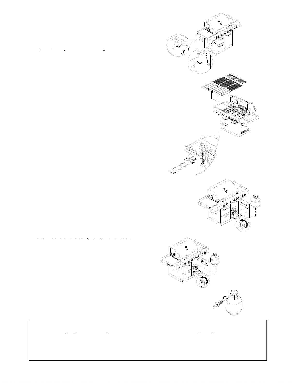
A tank of approximately 12 inches in diameter by 18-
1/2 inches high is the maximum size LP gas tank to
Precautions
• near this appliance.
• Never fill the tank beyond 80 percent full . If this
information is not followed exactly, a fire causing
death or serious injury may occur.
• Always keep LP gas tanks in an upright position.
• Do not store (or) or use gasoline or other flammable
vapors and liquids in the vicinity of this gas grill.
• Do not subject the LP gas tank to excessive heat.
Nt LPtkidIft
use.
Y
ou must use an OPD gas tank which offers
an Overfill Prevention Device.
This safety feature prevents the tank from being
overfilled which can cause malfunction of the LP gas
tank, regulator and/or grill.
The LP gas tank must be constructed and marked in
accordance with specifications of the U.S. Dept. of
T t ti (DOT) I C d th LP t k
•
N
ever s
t
ore an
LP
gas
t
an
k
i
n
d
oors.
If
you s
t
ore your
gas grill in the garage or other indoor location,
always disconnect the LP gas tank first and store it
safely outside.
T
ranspor
t
a
ti
on
(DOT)
.
I
n
C
ana
d
a,
th
e
LP
gas
t
an
k
must meet the National Standard of Canada ,Can
CSA –B339 , Cylinders , spheres and Tubes for
Transportation of Dangerous Goods and Commission .
1. The LP gas tank must have a shutoff valve,
terminating in an LP gas supply tank valve outlet, that
is compatible with a Type 1 tank connection device.
The LP gas tank must also have a safety relief device
that has a direct connection with the vapor space of
• Place dust cap on cylinder valve outlet whenever the
cylinder is not in use. Only install the type of dust
cap on the cylinder valve outlet that is provided with
the cylinder valve. Other types of caps or plugs may
result in leakage of propane.
•
LP gas tanks must be stored outdoors in a well
that
has
a
direct
connection
with
the
vapor
space
of
the tank.
2. The tank supply system must be arranged for vapor
withdraw.
3. The LP gas tank used must have a collar to protect
the tank valve.
Proper Placement and Clearance of Grill
Never
use your gas grill in a garage porch shed
•
LP
gas
tanks
must
be
stored
outdoors
in
a
well
-
ventilated area and out of reach of children.
Disconnected LP gas tanks must not be stored in a
building, garage or any other enclosed area.
• When your gas grill is not in use the gas must be
turned off at the LP gas tank.
• The regulator and hose assembly must be inspected
before each use of the grill. If there is excessive
abrasion or wear or if the hose is cut it must be
Never
use
your
gas
grill
in
a
garage
,
porch
,
shed
,
breezeway or any other enclosed area. Your gas grill
is to be used outdoors only, at least 24 inches from
the back and side of any combustible surface. Your
gas grill should not be used under overhead
combustible construction. Do not obstruct the flow of
ventilation air around the gas grill housing.
• Do not install this outdoor gas grill in or on
recreational vehicles or boats
abrasion
or
wear
or
if
the
hose
is
cut
,
it
must
be
replaced prior to the grill being used again.
• Keep the gas regulator hose away from hot grill
surfaces and dripping grease. Avoid unnecessary
twisting of hose. Visually inspect the hose prior to
each use for cuts, cracks, excessive wear or other
damage. If the hose appears damaged do not use
the gas grill. Call 1-800-4-MY-HOME for assistance.
•
Never
light your gas grill with the lid closed or before
recreational
vehicles
or
boats
• Keep outdoor gas grill area clear and free from
combustible materials, gasoline and other flammable
vapors and liquids
•Do not obstruct the flow of combustion and ventilation
air. Check for this each time prior to using grill.
•Never connect an unregulated LP gas tank to your
gas grill. The gas regulator assembly supplied with
y
our
g
as
g
rill is ad
j
usted to have an outlet
p
ressure of
Never
light
your
gas
grill
with
the
lid
closed
or
before
checking to ensure the burner tubes are fully seated
over the gas valve orifices.
•Never allow children to operate your grill.
•Warning: The grilling unit, including, if applicable,
built in refrigerator, built in lights, should never be left
unattended while in use. After use of the grill, always
turn off all burners and the main gas supply on the
p
ro
p
ane tank, remove the tank and un
p
lu
g
all
ygg j p
11” water column (W.C.) for connection to an LP gas
tank.
• Only use the regulator and the hose assembly
supplied with your gas grill. Replacement regulators
and hose assemblies must be those specified in this
manual.
pp pg
electronic components before covering your grill for
storage, to prevent personal injuries or property
damage.
2

WARNING
A strong gas smell, or the hissing sound of gas
indicates a serious problem with your gas grill or
the LP gas tank. Failure to immediately follow the
steps listed below could result in a fire or
explosion that could cause serious bodily injury
!Burner Flame Check
explosion
that
could
cause
serious
bodily
injury
,
death, or property damage.
• Shut off gas supply to the gas grill.
• Turn the control knobs to OFF position.
• Put out any flame with a proper fire extinguisher.
• Open Grill Lid.
• Get away from the LP gas tank.
• Do not try to fix the problem yourself.
•
If odor continues or you have a fire you can not
Visually check the burner flames prior to each use. The
flames should look like
p
icture
,
if the
y
do not
,
refer to the
•
If
odor
continues
or
you
have
a
fire
you
can
not
extinguish, call your fire department. Do not call
near the LP gas tank because your telephone is
a form of electrical device and could create a
spark resulting in fire and/or explosion.
NOTE: The normal flow of gas through the regulator
and hose assembly can create a humming noise A
p,y ,
cleaning burner tubes and ports, see page 14 of this
manual.
Repair Protection Agreements
Congratulations on making a smart purchase. Your new
Kenmore product is designed and manufactured for
years of dependable operation. But like all products, it
ma
y
re
q
uire re
p
air from time to time. That's when havin
g
and
hose
assembly
can
create
a
humming
noise
.
A
low volume of noise is perfectly normal and will not
interfere with operation of the grill. If humming noise
is loud and excessive you may need to purge air from
the gas line or reset the regulator excess gas flow
device. This purging procedure should be done every
time a new LP gas tank is connected to your grill. For
help with this procedure refer to page 11, Item 4 of “If
Grill Still Fails To Light”, or call the Customer Service
Helpline 8 AM to 5 PM PST at: 1
800
913
8999
yq p g
a Repair Protection Agreement can save you money and
aggravation.
Here’s what the Repair Protection Agreement *
includes:
9Expert service by our 10,000 professional repair
specialists
9Unlimited service and no charge for parts and labor
ll d i
CAUTION: Beware of Flash-Back
Helpline
8
AM
to
5
PM
PST
at:
1
-
800
-
913
-
8999
Once you purchase the Repair Protection Agreement, a
simple phone call is all that it takes for you to schedule
on a
ll
covere
d
repa
i
rs
9Product replacement up to $1500 if your covered
product can’t be fixed
9Fast help by phone - we call it Rapid Resolution -
phone support from a Sears representative. Think of
us as a “talking owner’s manual”
CAUTION: Spiders and small insects occasionally
spin webs or make nests in the grill burner tubes
during transit and warehousing. These webs can lead
to gas flow obstruction which could result in a fire in
and around burner tubes. This type of fire is known as
“FLASH-BACK” and can cause serious damage to
your grill and create an unsafe operating condition for
the user.
service. You can call anytime day or night, or schedule a
service appointment online.
The Repair Protection Agreement is a risk-free purchase.
If you cancel for any reason during the product warranty
period, we will provide a full refund. Or, a prorated refund
anytime after the product warranty period expires.
Purchase your Repair Protection Agreement today!
Some limitations and exclusions apply. For prices
d dditi l i f ti i th U S A ll
Although an obstructed burner tube is not the only
cause of “FLASH-BACK”, it is the most common
cause.
To reduce the chance of “FLASH-BACK”, you must
clean the burner tubes before assembling your grill,
and at least once a month in late summer or early fall
when spiders are most active. Also perform this burner
tube cleaning procedure if your grill has not been used
an
d
a
dditi
ona
l
i
n
f
orma
ti
on
i
n
th
e
U
.
S
.
A
. ca
ll
1 -800-827-6655.
*Coverage in Canada varies on some items. For Full
details call Sears Canada at 1-800-361-6665
Sears Installation Service
For Sears professional installation of home appliances,
garage door openers, water heaters, and other major
home items, in the U.S.A. or Canada call 1-800-4-MY-
HOME
for an extended period of time.
See Cleaning Burner Tubes and Ports on page # 14.
3
HOME

Model 122.16648901 Parts Diagram
02
01
02
04
07
92
91
02
05
06
03
05
10
09
11
07
12
90
89
78
77
76
71
70
13
87
81
82
83 85
10
79
80
8
8
86
84
05
74 75
08
74
77
73
72
69
07
68
62 67
15
19
16
20
21 17
18
10 14
22
61
93
66
63
65
56
58
59
2
3
27
28
29
26
24
55
25 64
57
22
60
32
30
29
54
55
35
47
50 48
49
4
5
53
53
52
45
51
34
31
30
31
33
36
38 30
4
3
42
44
46
37
30
30
31
39
40
41
4
40

Model122.16648901 Parts List
KEY# PARTS DESCRIPTION QUANTITY KEY# PARTS DESCRIPTION QUANTITY
1
650A 001A
Main Lid
1
48
650A 048
Tank Tray
1
1
650A
-
001A
Main
Lid
1
48
650A
-
048
Tank
Tray
1
2 650A-002 Main Lid Screw 2 49 650A-049 Tank Bolt 1
3 650A-003 Temperature Gauge 1 50 650A-050 Swivel Caster 1
4 650A-004B Logo 1 51 650A-051N BottomPanel 1
5 650A-005 Hood Buffer 2 52 650A-052O Cart Clapboard 1
6 650A-006 Main Lid Handle 1 53 650A-053 Caster 2
7 650A-007C Side Shelf, Side burner back bracket 2 54 650A-054P Side Panel, Right 1
8 650A-008 Side Shelf Handle, Left 1 55 650A-055Q Back Panel 1
9 650A-009D Side Shelf Front Panel, Left 1 56 650A-056 Rubber Grommet 1
10 650A-010 Hooks 4 57 650A-057 Firebox Heat Shield 1
11 650A-011 Bottle Opener 1 58 650A-058 Cable Strainer 1
12 650A-012E Side Shelf, Left 1 59 650A-059
R
Power Cord Bracket 1
13 650A-013F Front Baffle 1 60 650A-060Z Transformer 1
14 650A-014 Igniter Junction Wire 1 61 650A-061S Lamp Cord 1
15 650A-015 Main Gas Valve 5 62 650A-062 Electronic Igniter Module 1
16 650A-016G Main Manifold 1 63 650A-063 Sear Gas Valve 1
17 650A-017 Regulator, LP 1 64 650A-064 Side Manifold 1
18 650A-018 Side Burner Hose 1 65 650A-065 Sear Burner Igniter Wire 1
19 650A-019 Rotisserie Gas Valve 1 66 650A-066 Sear Burner 1
20 650A-020H Main Control Panel 1 67 650A-067T Side Burner Control Panel 1
21 650A-021 Control Knob 6 68 650A-068U Sear Burner Bowl Assembly Frame 1
22
650A
-
022
Rotisserie Control knob
1
69
650A
-
069
Side Burne Grease Tray
1
22
650A 022
Rotisserie
Control
knob
1
69
650A 069
Side
Burne
Grease
Tray
1
23 650A-023 Ligh Switch 1 70 650A-070 Side Burner Cooking Grid 1
24 650A-024Y Side Panel, Left 1 71 650A-071 Side Burner Lid 1
25 650A-025 Swivel Caster w ith Brake 1 72 650A-072V Grease Slide Panel, Bottom 1
26 650A-026 Door Hinge 1 73 650A-073 Grease Tray 1
27 650A-027 Door Clapboard 1 74 650A-074 Lamp 2
28 650A-028 Drawer Slide Bracket, Left 1 75 650A-075W Lamp Fix Cover 1
29 650A-029J Draw er Slide 2 76 650A-076X Back Panel, Top 1
30 650A-030 Drawer, Door Handle Seat 6 77 650A-077 Rotisserie Burner Flex Gas Line 1
31 650A-031 Drawer, Door Handel Tube 3 78 650A-078 Rotisserie Orifice w / brass elbow 1
32 650A-032K Draw er 1 79 650A-079 Rotisserie Burner Igniter Wire 1
33
650A 033
DM t
2
80
650A 080
Rti i B G Cll t
1
33
650A
-
033
D
oor
M
agne
t
2
80
650A
-
080
R
o
ti
sser
i
e
B
urner
G
as
C
o
ll
ec
t
or
1
34 650A-034L Cart Frame 1 81 650A-081 Rotisserie Burner 1
35 650A-035 Door hinge bracket, Left 1 82 650A-082 Rotisserie Heat Shield 1
36 650A-036 Door hinge bracket, Right 1 83 650A-083 Rear baffle 1
37 650A-037 Door, Front 1 84 650A-084ZA Main Burner Igniter Wire A 1
38 650A-038 Door, Right 1 85 650A-085ZB Main Burner Igniter Wire B 1
39 650A-039 Lighting Rod 1 86 650A-086Z
C
Main Burner Igniter Wire C 1
40 650A-040 Triangle Bracket 2 87 650A-087ZD Main Burner Igniter Wire D 1
41 650A-041 L Shape Bracket 2 88 650A-088ZE Main Burner Igniter Wire E 1
42 650A-042 Tow el Rack 1 89 650A-089 Main Burner 5
43 650A-043 Tow el Rack Bracket 2 90 650A-090 Heat Diffuser 5
For assembly questions, call:
1-800-913-8999 Important: Use only parts listed above. When ordering
parts, providing the following information:
44 650A-044 Tank Tray Lock Slip 1 91 650A-091 Cooking Grid With Hole 3
45 650A-045M Tank Tray Slide 2 92 650A-092 Warming Rack 1
46 650A-046 Tank Tray Slide Bracket, Right 1 93 650A-093 Bezel 6
47 650A-047 Tank Tray Slide Bracket, Left 1
For parts ordering, please call:
1-800-4-MY-HOME
To make sure you obtain the correct replacement
parts for your Kenmore gas grill, please refer to
the part numbers on this page.
Important:
Keep this Owner
’
s Manual for
1. Model #
2. Part Number (see PART# in chart)
3. Part Description
4. Quantity of parts needed
®
You can purchase the Kenmore
rotisserie kit, item # 15803 at your
local Sear's or Kmart store.
Important:
Keep
this
Owner s
Manual
for
convenient reference and for part replacement.
5
Also this grill can be converted to a
NG grill. Please call 1-800-4-MY-
HOME and request part # 710-0650.

CAUTION: While it is possible for one person to
assemble this grill, obtain assistance from another
person when handling some of the larger, heavier pieces
1. Open lid of shipping carton and remove top sheet of
Unpacking Instructions Figure 1
A
cardboard. Lay cardboard sheet on floor and use as a work
surface to protect floor and grill parts from scratches
2. Remove packing materials from shipping carton.
3. You may slice the carton front corners with a utility knife to
lay open the carton front panel. This will allow you to raise
the grill head lid and remove the components packed
inside the head.
4
Use the parts list to check that all parts have been included
Figure 2
B
A
4
.
Use
the
parts
list
to
check
that
all
parts
have
been
included
.
5. With the aid of an assistant, lift grill up from shipping
platform and set grill down on floor.
Assembly Instructions
I t th ill f d bl it D t
Figure 3
A
I
nspec
t
th
e gr
ill
f
or
d
amage as you assem
bl
e
it
.
D
o no
t
assemble or operate the grill if it appears damaged. If there are
damaged or missing parts when you unpack the shipping box,
or you have questions during the assembly process, call: For
Assembly Questions, call 1-800-913-8999, 8 AM – 5 PM
PST, Monday through Friday.
CAUTION: Before moving on to side shelf assembly, remove
main grease tray and cup from back of grill and remove and
main
grease
tray
and
cup
from
back
of
grill
,
and
remove
and
discard any ties or packing material. Then reinsert tray/cup
assembly back into grill as below picture shown.
Assembling Side Burner Shelf
1. Remove (2) Phillips head screws & (2) lock washers from
side burner shelf and use them to attach backsplash,
sloped surface facing forward to shelf as shown (Fig 1 A)
B
sloped
surface
facing
forward
,
to
shelf
as
shown
(Fig
.
1
A)
.
Remove (4) Phillips head screws and lock washers from
the front of the side burner front panel and use them to
attach front panel to side burner (Fig.1B).
2. Remove (2) Phillips head screws & (2) lock washers from
side burner shelf. (Fig. 2).
3
.L
oose
n
(
2
)
Philli
ps
h
ead
sc
r
e
w
s
&
(
2
)
fl
at
w
as
h
e
r
s
&
l
oc
k
3
oose ( ) ps ead sc e s & ( ) at as e s & oc
washers on right side panel of grill( Fig. 3, A). Turn screws
out ¼’’ from panel.
4. Remove (1) Phillips head screw and flat washer (Fig. 3, B).
6

Assembling Side Burner Shelf, Continued
5. Hang side burner shelf on side panel by placing side
burner slotted screw holes over the 2 screws and
washers loosened in Step 3 (Fig. 4). Fix shelf to
panel with the (2) Phillips head screws and lock
washers removed in step 2 (Fig. 5, C).
Figure 5
C
washers
removed
in
step
2
(Fig.
5,
C).
6. Fully tighten the (2) screws loosened in step 3 (Fig.
5, D)
Installing Side Burner Valve
1. Locate the igniter wire hanging from side burner and
plug it into the open socket in igniter module. (Fig. 6)
Note:
If there is more than one open socket call
1
-
Note:
If
there
is
more
than
one
open
socket
,
call
1
-
800-913-8999 for assistance.
2. Locate the small wire emerging from the igniter
module and connect it to the terminal on the side
burner valve (Fig. 7).
3. Remove two screws and washers from front of side
burner valve (Fig. 8, A)
D
burner
valve
(Fig.
8,
A)
4. Insert rear stem of side burner valve into burner tube
hole (Fig. 8, B).
5. Insert bezel in front of side burner front panel, Insert
front stem of side burner valve through hole in side
burner control panel (Fig. 8, A.), Insert and tighten
the
(
2
)
screws and washers from ste
p
3 throu
g
h the
E
() p g
control panel bezel and into the side burner valve
(Fig. 8, A).
6. Push side burner control knob onto side burner valve
control stem. Secure knob to stem by using included
hex wrench to tighten set screw (Fig. 9)
7. Insert and tighten screw, washer and lock washer
E
removed in step 4 of Assembling Side Burner Shelf
(Fig. 5, E).
Figure 4 Figure 6
7

Figure 9
5/64’’ hex wrench
Installing Igniter Module
1. Remove silver battery cap and black hexagon plastic
nut from battery compartment of igniter module.
2. Position igniter module vertically so that battery
compartment is at the top of module.
3. Insert threaded stem of battery compartment through
Assembling Left Side Shelf
• Remove two Phillips head screws and lock washers from
side shelf front panel, attach bottle opener and tighten
screws and lock washers.(Fig.11,A)
•
Remove (4) Phillips head screws and lock washers from
Figure 10
hole in side burner control panel as shown (Fig. 10).
Tighten stem to panel using hexagon plastic nut.
Replace silver battery cap.
•
Remove
(4)
Phillips
head
screws
and
lock
washers
from
the back of the side shelf front panel and use them to
attach front panel to side shelf (Fig. 11,B).
• To attach left side shelf to grill, perform Steps 1 through 6
of Assembling Side Burner Shelf.
• Insert and tighten screw, washer and lock washer removed
in step 4 of Assembling Side Burner Shelf (Fig. 5, E).
• Remove Phillips head screw, washer and lock washer from
bezel at each end of towel bar and use them to attach
bezel
at
each
end
of
towel
bar
,
and
use
them
to
attach
towel bar and bezels to side shelf as shown (Fig. 12).
• Attach utensil hooks to side shelf as shown (Fig. 13, in next
page)
Figure 11
When you have finished assembling grill, make sure that all
screws and nuts are tight and secure. B
Figure 7
A
Figure 12
Figure 8
Figure
8
B
8
A

Installing Cooking Components
Important: Before cooking on your grill the first time,
wash cooking grids and cooking rack with warm ,
soapy water. Rinse and dry thoroughly. Season
with cooking oil regularly. After cooking is
com
p
leted
,
turn
g
rill to HIGH settin
g
for 3 to 5
Figure 13
p,g g
minutes to burn off excess grease or food residue.
1. Install heat diffusers above burners. Place the
holes in rear corners of diffusers attach onto pegs
in the back edge of firebox. Ensure that firebox
heat shield is inserted securely into slots between
adjacent burners. If grill was shipped with shield
taped in place, remove tape before using grill.
2
Evenly space cooking grids on the ledge above
2
.
Evenly
space
cooking
grids
on
the
ledge
above
heat diffusers. (Fig.14)
3. Insert the legs of the warming rack into the holes in
the tops of the grill bowl side panels. (Fig.14)
4. Insert the side burner grease tray as shown. (Fig.
15)
Connecting LP gas tank to LP grill
Figure14
Figure15
1. Open right door, unlock tank tray lock slip.(Fig.16).
Pull out tank tray, place foot ring of 20 lb tank into
the hole in tray. Make sure the tank valve is on
OFF position. Use the tank bolt to secure the tank
in a fixed position.(Fig.17)
2. Check the tank valve to ensure it has proper
external mating threads to fit the hose and
regulator assembly provided.
3. Make sure all burner valves are in OFF position.
4. Inspect the valve connection port and regulator
assembly. Look for damage or debris. Remove any
debris. Inspect hose for damage. Never use
damaged or plugged equipment.
5. When connecting regulator and hose assembly to
tank valve hand tighten quick coupling nut
clockwise to a full stop. (Fig.18) Do not use a
Figure17
Figure16
clockwise
to
a
full
stop.
(Fig.18)
Do
not
use
a
wrench to tighten because it could damage the
quick coupling nut and result in a hazardous
condition.
6. Open tank valve fully (counterclockwise). Use a
soapy water solution to check all connections for
leaks before attempting to light your grill. If a leak
is found, turn tank valve off and do not use your
grill until the leak is repaired. Regulator Connection
Congratulations
Your Kenmore
g
as
g
rill is now read
y
for use. Before the first use and at the be
g
innin
g
of each season
(
and
Figure 18
CAUTION: When the appliance is not in use, gas
must be turned off at the supply tank.
gg y g g (
whenever the LP gas tank has been changed):
1. Read all safety, lighting and operating instructions.
2. Check gas valve orifices, burner tubes and burner ports for any obstructions.
3. Perform gas leak check according to instructions found on this page of the manual.
9

6. To light additional burners, push and turn burner
knob(s) to HI or ON and hold in for 3 to 5
seconds until burner(s) ignites, then adjust
knob(s) to desired setting.
1. Make a 50/50
(
soa
p
/water
)
mild soa
p
solution.
Checking for LP gas leaks
Never test for leaks with a flame. Prior to first use, at
the beginning of each season, or every time your LP
gas tank is changed, you must check for gas leaks.
7. If the burner does not light after 5 seconds, turn
k b t OFF T OFF t LP t k d it 5
(p ) p
2. Turn the control knobs to full OFF position; then turn
gas ON at supply tank.
3. Apply the soap solution with a clean brush to all gas
connections. See below. If growing bubbles appear
in the solution the connections are not properly
sealed. Check each fitting and tighten or repair as
necessary.
Gas Connection Leak Check
k
no
b
t
o
OFF
.
T
urn gas
OFF
a
t
LP
t
an
k
an
d
wa
it
5
minutes for gas to clear. Then turn gas ON at
tank and repeat step 5.
8. If burner still does not light, see Match Lighting
section and If Grill Still Fails to Light section on
following page.
Gas
Connection
Leak
Check
LIGHTING INSTRUCTIONS FOR ROTISSERIE BURNER
4. If you have a gas connection leak you cannot repair,
turn gas OFF at supply tank, disconnect fuel line
from your grill and call 1-800-4-MY-HOME or your
gas supplier for repair assistance.
5. Also apply soapy solution to the tank seams. See
below. If growing bubbles appear, shut tank OFF
and do not use or move it! Contact an LP gas
supplier or your fire department for assistance.
1. Open lid during lighting.
2. To ignite, turn rotisserie knob to ON, hold for 3 to
5 seconds until burner ignites. If ignition does not
occur in 5 seconds, turn knob to OFF, wait 5
minutes and repeat the lighting procedure.
3. Important: When using the Rotisserie Burner, do not
use the Main Burners.
4. If burner still does not light, see Match Lighting
USING THE SIDE BURNER:
Inspect the gas supply hose prior to turning the gas
“ON”. If there is evidence of cuts, wear or abrasion,
it must be replaced prior to use. Do not use the
id b if th d f i t
Gas Tank Leak Check
section and If Grill Still Fails to Light Section on
following page.
Grill Lighting Instructions for Burner
1. Do not smoke while lighting grill or checking
gas supply connections.
2. Be sure that LP gas tank is sufficiently full.
3. Be sure all gas connections are securely
LIGHTING INSTRUCTIONS FOR SIDE BURNER
• Open side burner lid fully.
• Push and turn side burner knob to ON
p
osition
,
s
id
e
b
urner
if
th
e o
d
or o
f
gas
i
s presen
t
.
WARNING: Always keep your face and body as
far away from the burner as possible when
lighting.
Grill Lighting Instruction
tightened.
4. Open the grill main lid and side burner lid.
5. Push and turn any main burner knob to HI
position, hold in for 3 to 5 seconds until burner
ignites.
p,
hold in for 3 to 5 seconds until burner ignites.
• If the side burner does not light after 5 seconds,
turn knob to OFF, turn gas OFF at LP tank and
wait 5 minutes for gas to clear. Then turn gas ON
at tank and repeat step 2.
• 4. If burner still does not light, see Match Lighting
section and If Grill Still Fails to Light section on
following page.
WARNING
Failure to open grill lid during the lighting
procedure could result in a fire or explosion
that could cause serious bodily injury, death,
or property damage.
!
10

WARNING
Never lean over the grill cooking area while
lighting your gas grill. Keep your face and body a
safe distance (at least 18 inches) from the
ki id f h li hti ill b
If Grill Still Fails To Light
1. Check gas supply and connections for leaks. Check
that all wires connections are secure.
2 Repeat basic lighting procedure If your grill still fails
!
coo
ki
ng gr
id
sur
f
ace w
h
en
li
g
hti
ng your gr
ill
b
y
match.
2
.
Repeat
basic
lighting
procedure
.
If
your
grill
still
fails
to operate, turn the gas off at source, turn the control
knobs to OFF, then check the following:
• Misalignment of burner tubes over orifices
Correction: Reposition burner tubes over orifices.
•Obstruction in gas line
Correction: Remove fuel line from grill. Do not smoke!
Open gas supply for 1 second to clear any obstruction
Manually Lighting Your Grill by Match
1. Take the manual lighting stick
2. Insert a match into the lighting stick.
3 Follow steps 1 through 5 of the Basic Lighting
Open
gas
supply
for
1
second
to
clear
any
obstruction
from fuel line. Close off gas supply at source and
reconnect fuel line to grill.
• Plugged orifice
Correction: Remove burners from grill, carefully lift
each burner up and away from gas valve orifice.
Remove the orifice from gas valve and gently clear any
obstruction with a fine wire. Then reinstall all orifices
,
3
.
Follow
steps
1
through
5
of
the
Basic
Lighting
Procedure.
4. Light the match and extend the lighting stick to
cooking grid surface.
5. Turn the desired control knob to the HI/position
setting to release gas. The burner should light
immediately
,
burners, and cooking components.
3. If an obstruction is suspected in gas valves, please
call for repair service at 1-800-4-MY-HOME.
4. If the grill still does not light you may need to purge air
from the gas line or reset the regulator excess gas flow
device. Note: This procedure should be done every time
immediately
.
a new LP gas tank is connected to your grill.
To purge air from your gas line and/or reset the
regulator excess gas flow device:
• Turn the control knob to OFF position.
• Turn off the gas at the tank valve.
• Disconnect regulator from LP gas tank.
• Let unit stand for 5 minutes.
• Reconnect regulator to the LP gas tank.
• Turn the tank valve on slowly until ¼ to ½ open.
• Open the grill lid.
• Set control knobs to OFF. Push and turn any control
knob to HIGH.
• Turn control knobs to HIGH until all the burners are lit
• You may start to use the grill
5If ll h k ti h b d d
WARNING
Should a “FLASH-BACK” fire occur in/or
!
5
.
If
a
ll
c
h
ec
k
s or correc
ti
ons
h
ave
b
een ma
d
e an
d
you
still have questions about operating your gas grill, call
the Customer Service Helpline 8 AM – 5 PM PST,
Monday through Friday at 1-800-913-8999
around the burner tubes, follow the instructions
below. Failure to comply with these instructions
could result in a fire or explosion that could
cause serious bodily injury, death, or property
damage.
• Shut off gas supply to the gas grill.
• Turn the control knobs to OFF position.
• Put out any flame with a proper fire extinguisher.
• Open grill lid.
• Once the grill has cooled down, clean the burner
tubes and burners according to the cleaning
instructions found on page 14.
11

1.Make sure the light power switch on the control
panel is in the “OFF” position.
2.Turn the light power switch to
“
OFF.
”
Light Operation Instructions
2.Turn
the
light
power
switch
to
OFF.
WARNING
Keep any electrical supply cord away from any
heated surface.
Halogen Bulb Replacement
1
Make sure that the grill has cooled before changing the
!Picture A
1
.
Make
sure
that
the
grill
has
cooled
before
changing
the
light bulb.
2.Make sure the light’s power switch on the control panel
is in the “OFF” position and power plug is disconnected
from the outlet.
3.Use a Phillips screwdriver to loosen 8pcs screws & 8pcs
washers
securing the light
rear cover
on the left end and
Picture B
washers
securing
the
light
rear
cover
on
the
left
end
and
the right end as Picture A shown.
NOTE: When removing final screw from lamp rear cover,
make sure to use other hand to hold the cover in place,
ensuring it doesn’t fall and damage.
4. Loose one screw securing the light glass cover ,.
also
need
to
use
other
hand
to
hold
the
cover
Picture C
also
need
to
use
other
hand
to
hold
the
cover
,
ensuring it doesn’t fall and shatter.
As shown in Picture B
5.Remove the glass cover from the light bulb housing.
See Picture C&D.
Picture
C
HINT: Use a flathead screwdriver to open it easily.
Picture D
6. Use a flathead screwdriver to loosen the four screws
locking the bulb in place.
Loosen but do not remove four screws from light first as
Picture E
picture E shown.
12

7. Pull out the light bulb and replace with a new
bulb as Picture F, then tighten the four screws
which were loosen in picture E.
Note: Do not touch the halogen bulb with bare hands.
Picture F
8. Replace glass cover, reinsert light bulb housing into
the grill, and insert and tighten all the screws. Picture G. Picture G
9. Attach original lamp rear cover with original 8pcs
screws and washers to back panel of firebox and
tighten screws as Picture H.
tighten
screws
as
Picture
H.
Picture H
Cleaning Method
Follow steps 1 through 4 above for glass cover removal. Use a damp towel to clean the surface of the
glass cover. Make sure the glass cover is completely dry before re-installing.
WARNING
Make sure the light switch is in the “OFF” position and the power plug is disconnected from the
power outlet prior to cleaning the glass cover.
!
WARNING
The glass cover should not be in contact with water or any other liquid when it’s warm. Sudden
change of temperature may cause cracks in the glass.
WARNING
!
!
WARNING
To ensure continued protection against electric shock:
1. Connect to properly grounded outlets only.
2. Do not expose to rain.
3. Keep extension cord connections dry and off the ground.
Bulb Type: Halogen
!
Bulb
Type:
Halogen
Wattage: 10 watts per bulb
Voltage: 12 volts
.
If you still have questions about replacing bulb, call the Customer Service Helpline 8 AM – 5 PM
PST, Monday through Friday at 1-800-913-8999.
13

To ensure a proper working unit the following proper
care and maintenance is suggested.
Cleaning Cooking Grids
Cleaning Exterior Stainless Steel Surfaces
•Weathering and extreme heat can cause exterior
stainless steel surfaces to turn tan in color. Machine
oils used in manufacturing process of stainless steel
Cleaning and Maintenance
We suggest you wash your cooking grids in a mild soap
and warm water solution. You can use a wash cloth or
soft brush to clean your cooking grids.
Cleaning Heat diffusers
Periodically you should wash the heat diffusers in a
soap and warm water solution. Use a soft brush to
remove stubborn burnt-on cooking residue. The heat
oils
used
in
manufacturing
process
of
stainless
steel
can also cause this tanning color. Use a stainless
steel cleaner to polish stainless steel surfaces of
your grill. Never use abrasive cleaners or scrubbers
because they will scratch and damage your grill.
Cleaning Burner Tubes and Burner Ports
diffusers should be dry before you reinstall them.
Cleaning Grease Tray
The grease tray should be emptied and wiped
down periodically and washed in a mild
detergent and warm water solution. A small
amount of sand or cat litter may be placed in
bottom of grease tray to absorb the grease.
Ch k th t f tl d ’t ll
To reduce the chance of “FLASH-BACK” the procedure
below should be followed at least once a month in late
summer or early fall when spiders are most active or
when your grill has not been used for a period of time.
1. Turn all burner valves and gas tank valve to off
position.
2 Detach the LP gas regulator assembly from your gas
Ch
ec
k
th
e grease
t
ray
f
requen
tl
y,
d
on
’t
a
ll
ow
excess grease to accumulate and overflow out of the
grease tray.
Annual Cleaning of Grill Interior
Burning-off the grill after every use will keep it ready for
your next use. However, once a year you should give
the entire grill a thorough cleaning to keep it in top
ti diti F ll th t
2
.
Detach
the
LP
gas
regulator
assembly
from
your
gas
grill.
3. Remove cooking grids, heat diffusers, and grease
tray from the grill.
4. Remove the screws from the underside of each
burner and lift the burners up and away from the gas
valve orifice.
5. Using a bent stiff wire in the shape of a hook , air
hose or a bottle brush run it through the burner tube
opera
ti
ng con
diti
on.
F
o
ll
ow
th
ese s
t
eps.
1. Turn all burner valves to full OFF position.
2. Turn LP gas tank valve to full OFF position.
3. Detach LP gas hose and regulator assembly from
your gas grill. Inspect for any damage and replace as
necessary with manufacturer replacement part number
found on parts list.
4. Remove and clean heat diffusers, cooking grids and
grill burners
hose
or
a
bottle
brush
,
run
it
through
the
burner
tube
and inside several times to remove any debris.
6. Replace burners, see illustration below.
Step 1. Locate the burner onto the orifice.
Step 2. Secure the main burner on the back wall of fire
box with 2 screws.
grill
burners
.
5. Cover each gas valve orifice with aluminum foil.
6. Brush inside and bottom of grill with a nylon brush,
and wash with a mild soap and warm water solution.
Rinse thoroughly and let dry.
7. Remove the aluminum foil, then reinstall heat
diffusers, and cooking grids.
8. Reconnect gas source and observe burner flame for
correct operation
correct
operation
.
Cleaning Exterior Surface
•We suggest you wash your grill using a mild soap and
warm water solution. You can use a wash cloth or
sponge for this process. Do not use abrasives or a
brush that might remove finish during the cleaning
process. WARNING
The location of the burner tube with respect to the
orifice is vital for safe o
p
eration. Check to ensure the
!
14
p
orifice is inside the burner tube before using the gas
grill. If the burner tube does not fit over the valve
orifice, lighting the burner may cause explosion
and/or fire.

Regardless of which burner cleaning procedure you
use, we recommend you also complete the following
steps to help prolong burner life.
1. Use a fiber pad or nylon brush to clean the entire
outer surface of each burner until free of food residue
3. Inspect each burner for damage (cracks or holes)
and if such damage is found, order and install a new
burner. After installation check to ensure that gas
valve orifices are correctly placed inside the ends of
the burner tubes.
and dirt.
2. Clean any clogged ports with a stiff wire, such as
an open paper clip.
WARNING
Spiders and insects can nest inside the burners of
the grill and disrupt gas flow. This very dangerous
condition could cause a fire behind the valve panel,
thereby damaging the grill and making it unsafe for
operation. Inspect the grill at least twice a year.
!
BEFORE CALLING FOR SERVICE
If the grill does not function properly, use the following check list before calling for service.
You should ins
p
ect the burners at least once a
y
ear or immediatel
y
after an
y
of the followin
g
Troubleshooting
pyyyg
conditions occur:
PROBLEMS WHAT TO DO
Check to see ifLP tank is empty.
Clean wires and/or electrode by rubbing
ih l hl d l b
Grill won’t light when the control knob is
rotated.
w
i
t
h
a
l
co
h
o
l
an
d
c
l
ean swa
b
.
Wipe with dry cloth.
Make sure the wire is connected to
electrode assembly.
Do other burners on the unit operate?
Check to see if other burners operate. If
Check
to
see
if
other
burners
operate.
If
so, check the gas orifice on the
malfunctioning burner for an obstruction.
Burner flame is yellow or orange, in
combination with the odor of gas. Refer to Clean Burner Tubes and Burner
Ports on page 14. If problem still exists,
please call 1-800-913-8999.
Low heat with knob in “HI” position. Is the fuel hose bent or kinked?
Is the grill in a dusty area?
Is there adequate gas supply available?
If it is only one burner that appears low,
does the orifice or burner need cleaning?
Is the gas supply or gas pressure low?
15

Cooking Instructions
!
WARNING
Indirect Cooking
To cook indirectly, the food should be placed on
the left or right side of your grill with the burner lit
on the opposite side I
ndirect cooking must be
!
WARNING
Do not leave the grill unattended.
Your grill will get very hot. Never lean over
the cooking area while using your grill. Do not
touch cooking surfaces, grill housing. Grill Lid
or any other grill parts while the grill is in
operation, or until the grill has cooled down
after use. Failure to comply with these
instructions ma
y
result in serious bodil
y
in
j
ur
y
.
on
the
opposite
side
.
I
ndirect
cooking
must
be
done with the Lid down.
Flare-ups
The fats and juices dripping from grilled food can
cause flare-ups. Since flare-ups impart a
favorably,distinctive taste and color to food cooked
cover an open flame, they should be accepted up
to a point Nevertheless uncontrolled flaring can
yyjy
Burn-off
Before cooking on your gas grill for the first time,
you will want to “burn off” the grill to eliminate any
odor or foreign matter. Just ignite the
burners,lower the Lid, and operate grill on the
to
a
point
.
Nevertheless
,
uncontrolled
flaring
can
result in a ruined meal.
CAUTION
To prevent damage to adjacent burner(s), the
!
HIGH setting for 3 to 5 minutes.
Cooking Temperatures
High setting: Only use this setting for fast
warm-up,searing steaks or chops and for burning
food residue off the grill after cooking is complete.
Never use the HIGH setting for extended cooking.
Medium to Low Settings:
Most recipes specify
fire box heat shield must be securely inserted
in place when operating the Searing burner.
Medium
to
Low
Settings:
Most
recipes
specify
medium to low settings, including all smoking,
rotisserie cooking and for cooking lean cuts such
as fish.
NOTE: Temperature settings will vary with the
temperature and the amount of wind outside your
home.
Direct Cooking
Direct
Cooking
The direct cooking method can be used with the
supplied cooking grids and food placed directly
over the lit grill Burners. Direct cooking requires
the grill lid to be up.The method is ideal for
searing and whenever you want meat, poultry or
fish to have and open-flame barbecued taste.
Deep frying and smoking are also best cooked in
this manner because they require direct heat.
WARNING
Do not line the bottom of the grill housing with
aluminum foil, sand or any substance that will
restrict the flow of grease into the grease tray.
!
Failure to comply with these instructions could
result in a fire or explosion which could cause
serious bodily injury, death, or property
damage.
16

Grill Cooking Chart
FOOD Weight or thickness Temperature Time Special instructions and tips
Vegetables
NA
Medium
8to20minutes
Slice or chop vegetables and dot with butter or
margarine Wrap tightly in heavy duty foil Grill
Vegetables
NA
Medium
8
to
20
minutes
margarine
.
Wrap
tightly
in
heavy
duty
foil
.
Grill
turning occassionally.
Potatoes Whole Medium 40 to 60 minutes Wrap individually in heavy duty foil. Cook
rotating occassionally.
Meat/Steaks
1/2to3/4inches
High-Medium
4to15minutes
Pre heat grill for 15-20 minutes then sear
steaks on each side for two minutes. Next
Meat/Steaks
1/2
to
3/4
inches
High-Medium
4
to
15
minutes
grill 3 to 5 minutes on each side or until
desired doneness.
Ground Meats 1/2 to 3/4 inches Medium 8 to 15 minutes
Grill turning once when juices rise to the
surface or until desired amount of doneness.
Do not leave hamburgers unattended since a
flare-up could occur quickly.
Ribs 1/2 or full rack Medium 20 to 40 minutes Grill turning occassionally. During last few
minutes brush with barbecue sauce, turn
several times.
Hot dogs NA Medium 5 to 10 minutes Grill turning four times. 2-4 minutes on each of
four sides.
Gf
Poultry-Cut 1/4 to 1/2 pounds Low or Medium 20 to 40 minutes
G
rill turning occassionally. During last
f
ew
minutes brush with barbecue sauce if desired,
turn several times.
Low or 1 to 1-1/2 hours Use poultry stand and brush frequently as
desired
Medium 40 to 60 minutes Use poultry stand and brush frequently as
desired
Poultry Whole 2 to 3 pounds
Fish 3/4 to 1 inch Medium 8 to 15 minutes Grill turning once to desired doneness. Brush
with melted butter, margarine or oil.
17

This manual suits for next models
1
Table of contents
Other Sears Grill manuals