manuals.online logo
Brands
  1. Home
  2. •
  3. Brands
  4. •
  5. Sears
  6. •
  7. Heating System
  8. •
  9. Sears CSPHP Series User manual

Sears CSPHP Series User manual

Installation Instructions
NOTE: Read the entire instruction manual before starting the
instruction.
TABLE OF CONTENTS
PAGE
SAFETY CONSIDERATIONS ........................ 1
INTRODUCTION .................................. 1
INSTALLATION ................................... 2
Step 1--Check Existing Ductwork .................. 2
Step 2--Insulate and Vaporproof Duct ............... 2
Step 3--Install Coil in Supply Air Duct .............. 2
Step 4--Connect Refrigerant Piping ................. 2
Step 5--Connect Refrigerant, Liquid, and
Suction Lines ....................... 2
REFRIGERANT METERING DEVICE ................. 3
Step 1--Connect Condensate Lines ................. 3
MAINTENANCE ................................... 3
Air Filter ..................................... 3
Condensate Pan and Drain ........................ 3
Cleaning Coil .................................. 3
SAFETY CONSIDERATIONS
Improper installation, adjustment, alteration, service,
maintenance, or use can cause explosion, fire. electrical shock or
other conditions which may cause personal injury or property
damage. Consult a qualified installer, service agency, or your
distributor or branch for information or assistance. The qualified
installer or agency nmst use factory-authorized kits or accessories
when modifying this product. Refer to the individual instructions
packaged with the kits or accessories when installing.
Follow all safety codes. Wear safety glasses and work gloves. Use
quenching cloth for brazing operations. Have fire extinguisher
available. Read these instructions thoroughly and follow all
warnings and cautions attached to the unit. Consult local building
codes and National Electrical Code (NEC) for special
requirements.
It is important to recognize safety information. This is the
safety-alert symbol Z_' When you see this symbol on the unit
and in instructions or manuals, be alert to the potential fur
personal injury.
Understand the signal word DANGER, WARNING, CAUTION,
and NOTE. These words are used with the safety-alert symbol.
DANGER identifies the most serious hazards which win result in
severe personal injury or death. WARNING signifies hazards
which could result in personal injury or death. CAUTION is used
to identify unsafe practices, which may result in minor personal
injury or product and property damage. NOTE is used to
highlight suggestions which will result in enhanced
installation, reliability, or operation.
ELECTRICAL SHOCK HAZARD
Failure to follow this warning could result in personal
injury or death.
Before installing or servicing system, always turn off main
power to system. There may be more than one disconnect
switch. Turn off accessory heater power, if applicable.
UNIT OPERATION AND SAFETY HAZARD
Failure to follow this caution may result in personal injury
or equipment damage.
This coil contains nitrogen precharge of 15PSI. Release of
this pressure through the center of the rubber plugs is
required before removing the plug.
IMPORTANT: Nitrogen can leak out through the hole that the
needle pierced in the plugs. This does not indicate a leaking coil
nor warrant return of coil.
INTRODUCTION
Use these instructions to install Model CSPHP/CSRHP duct coils
in horizontal position. (See Fig. 1.) Model CSPHP/CSRHP duct
coils are designed and tested to conform to recommendations and
standards established by Air Conditioning and Refrigeration
Institute (ARI) Standard 210. It is easily adaptable to most types
of existing forced-air heating systems, or can be installed in an
independent air-cooling system.
l
Fig. 1 - CSPH Coil
A06520
NOTE: Models with tin-plated copper coils ("T" in the llth
position of the model number) are installed the same as standard
coils.
INSTALLATION
Step 1--Check Existing Ductwork
Inspect the previously installed air distribution system for heating
to determine its suitability for cooling. Existing heating ductwork
may have to be modified and insulated to provide better air
distribution for cooling.
Step 2--Insulate and Vaporproof Duct
Externally insulated ductwork must have an adequate vapor seal
for summer operation. This is particularly important where the
duct is exposed to high humidity conditions in attics, vented
crawl spaces, unconditioned basements and utility rooms. The
vapor seal prevents condensation in the insulating material and
subsequent loss of insulating value. Properly installed heating
supply ducts should already have adequate insulation against
excessive heat loss. This same insulation should, therefore, be
satisfactory in the summer for protection against heat gain.
However, depending on the specific installation, it may be
desirable to add to the insulation.
Step 3--Install Coil in Supply Air Duct
NOTE: For cooling-only units, coil can be installed in either
airflow direction. Heat pump applications require specific airflow
direction to obtain performance. See Fig. 1.
1. When the connecting air supply duct is smaller than the
coil inlet opening, construct transition piece so that vertical
and horizontal dimensions of transition piece do not
increase more than 30 °angle. If connecting outlet duct is
smaller than outlet opening of coil, limit transition to
maximum of 45 ° angle.
2. Provide at least 3 ft of straight ductwork preceding coil
inlet.
3. Support coil from floor or suspend it. When coil is sus-
pended, provide adequate hangers to hold coil.
NOTE: When coil is installed over a finished ceiling or living
area, a secondary condensate pan must be constructed and
installed under entire coil section.
Step 4--Connect Refrigerant Piping
Use field-supplied, refrigerant-grade tubing for connection to
outdoor units. Suction tube must be insulated. Do not use
damaged, dirty, or contaminated tubing because it may plug
refrigerant flow-control device. ALWAYS evacuate the coil and
field-supplied tubing before opening outdoor unit service valves.
Step 5--Connect Refrigerant, Liquid, and Suction
Lines
For matched and mismatched systems, use line sizes
recommended in outdoor unit Installation Instructions.
The coil can be connected to outdoor units using accesso U
tubing packages or field-supplied tubing of refrigerant grade.
Always evacuate tubing and reclaim refrigerant when making
connections or flaring tubing. Leak check connections before
insulating entire suction line.
1. Remove middle cabinet cover. Remove tubing cover and
slide cover with grommets onto the refrigerant lines (field
line set), away from braze joints.
2. Remove rubber plugs from coil stubs using a pulling and
twisting motion. Hold coil stubs steady to avoid bending
or distorting.
3. Wrap TXV and nearby tubing with a heat-sinking
material, such as a wet cloth.
4. Fit refrigerant lines into coil stubs. Wrap a heat-sinking
material, such as a wet cloth, behind braze joints.
5. Braze using a Sil-Fos or Phos-Copper alloy.
6. After brazing, allow joints to cool. Slide tubing plate with
rubber grommets over joints. Position tubing at center of
each grommet to ensure an air seal around the tube.
See Table 1 for coil connection tube size.
Table 1 - ('oil Connection Sizes
MODEL NUMBER TONNAGE
CS(ER)HP2412A(C,T)A 2
CS(ER)HP3012A(C,T)A 2-I/2
CS(ER)HP3612A(C,T)A 3
CS(ER)HP4212A(C,T)A 3-1/2
CS(ER)HP4812A(C,T)A 4
CS(ER)HP6012A(C,T)A 5
COIL CONNECTION
TUBE SIZE (IN.)
LIQUID SUCTION
3/8 5/8
3/8 3/4
3/8 3/4
3/8 7/8
3/8 7/8
3/8 7/8
UNIT DAMAGE HAZARD
Failure to follow this caution may result in product
damage.
To avoid damage while brazing, wrap tubing or fitting with
a heat-sinking material, such a wet cloth.
REFRIGERANT METERING DEVICE
CSPHP Models:
These coils have a factory-installed hard-shutoff TXV designed
only for use with R-410A refrigerant. Use only with outdoor
units designed for R-410A.
CSRHP Models:
These coils have a factory-installed hard-shutoff TXV designed
only for use with R-22 refrigerant. Use only with outdoor units
designed for R-22.
NOTE: ALL TXV'S HAVE PRESET SUPERHEAT
SETFINGS AND ARE FIELD NON-ADJUSTABLE.
Step l--Connect Condensate Lines
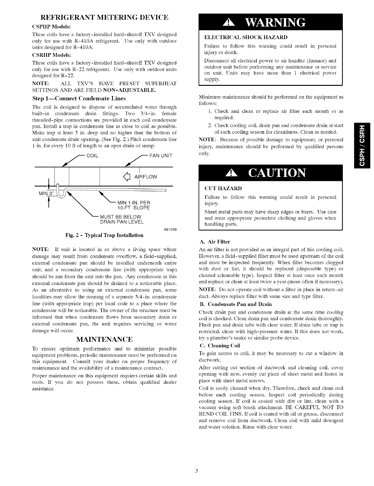
The coil is designed to dispose of accumulated water through
built-in condensate drain fittings. Two 3/4-in. female
threaded-pipe connections are provided in each coil condensate
pan. Install a trap in condensate line as close to coil as possible.
Make trap at least 3 in. deep and no higher than the bottom of
unit condensate drain opening. (See Fig. 2.) Pitch condensate line
1 in. for every 10 ft of length to an open drain or sump.
#_,S COIL f FAN UNIT
DRAIN PAN LEVEL
A91039
Fig. 2 -Typical Trap Installation
NOTE: If unit is located in or above a living space where
damage may result from condensate overflow, a field-supplied,
external condensate pan should be installed underneath entire
unit, and a secondary condensate line (with appropriate trap)
should be run from the unit into the pan. Any condensate in this
external condensate pan should be drained to a noticeable place.
As an alternative to using an external condensate pan, some
localities may allow the running of a separate 3/4-in. condensate
line (with appropriate trap) per local code to a place where the
condensate will be noticeable. The owner of the structure must be
informed that when condensate flows from secondary drain or
external condensate pan, the unit requires servicing or water
damage will occur. MAINTENANCE
To ensure optimum performance and to minimize possible
equipment problems, periodic maintenance must be performed on
this equipment. Consult your dealer on proper frequency of
maintenance and the availability of a maintenance contract.
Proper maintenance on this equipment requires certain skills and
tools. If you do not possess these, obtain qualified dealer
assistance.
ELECTRICAL SHOCK HAZARD
Failure to follow this warning could result in personal
injury or death.
Disconnect all electrical power to air handler (furnace) and
outdoor unit before performing any maintenance or service
on unit. Units may have more than 1 electrical power
supply.
Minimum maintenance should be performed on the equipment as
follows:
1. Check and clean or replace air filter each month or as
required.
2. Check cooling coil, drain pan and condensate drain at start
of each cooling season for cleanliness. Clean as needed.
NOTE: Because of possible damage to equipment, or personal
injury, maintenance should be performed by qualified persons
only.
CUT HAZARD
Failure to follow this warning could result in personal
injury.
Sheet metal parts may have sharp edges or burrs. Use care
and wear appropriate protective clothing and gloves when
handling parts.
A. Air Filter
An air filter is not provided as an integral part of this cooling coil.
However, a field-supplied filter must be used upstream of the coil
and must be inspected frequently. When filter becomes clogged
with dust or lint, it should be replaced (disposable type) or
cleaned (cleanable type). Inspect filter at least once each month
and replace or clean at least twice a year (more often if necessary).
NOTE: Do not operate coil without a filter in place in return-air
duct. Always replace filter with same size and type filter.
B. Condensate Pan and Drain
Check drain pan and condensate drain at the same time cooling
coil is checked. Clean drain pan and condensate drain thoroughly.
Flush pan and drain tube with clear water. If drain tube or trap is
restricted, clean with high-pressure water. If this does not work,
try a plumber's snake or similar probe device.
C. Cleaning Coil
To gain access to coil. it may be necessary to cut a window in
ductwork.
After cutting out section of ductwork and cleaning coil, cover
opening with new, evenly cut piece of sheet metal and fasten in
place with sheet metal screws.
Coil is easily cleaned when dry. Therefore, check and clean coil
before each cooling season. Inspect coil periodically during
cooling season. If coil is coated with dirt or lint, clean with a
vacuum using soft brush attachment. BE CAREFUL NOT TO
BEND COIL FINS. If coil is coated with oil or grease, disconnect
and remove coil from ductwork. Clean coil with mild detergent
and water solution. Rinse with clear water.
Copyright 2006 CAC /BDP • 7310 W. Morris St. • Indianapolis, iN 46231 Printed in USA. Edition Date: 09/06
Manufacturer reserves the right to change_ at any time_ specifications and designs without notice and without obligations.
Catalol_ No: IM-CSPH-02
Replaces:IM CSPH Ol

This manual suits for next models

25

Popular Heating System manuals by other brands

Toyotomi Oil Miser 23 Installation and operation instructions

Toyotomi

Toyotomi Oil Miser 23 Installation and operation instructions

Airxcel Aqua-Hot 100 Series Service manual

Airxcel

Airxcel Aqua-Hot 100 Series Service manual

DEFA WarmUp Bluetooth Fitting instructions

DEFA

DEFA WarmUp Bluetooth Fitting instructions

Vents VUT 300 E2V EC user manual

Vents

Vents VUT 300 E2V EC user manual

Sure Heat OVM21NG Insta;;ation and operating instructions

Sure Heat

Sure Heat OVM21NG Insta;;ation and operating instructions

Reflex Variomat Service instructions

Reflex

Reflex Variomat Service instructions

aerauliqa Quantum HR 100 installation manual

aerauliqa

aerauliqa Quantum HR 100 installation manual

Viessmann Vitocell 100-H Service instructions for contractors

Viessmann

Viessmann Vitocell 100-H Service instructions for contractors

Schulte Heizstab 5 user manual

Schulte

Schulte Heizstab 5 user manual

Velux Z0V Series Directions for use

Velux

Velux Z0V Series Directions for use

Sime Open Hybrid SMART 25-8 Installation and maintenance manual

Sime

Sime Open Hybrid SMART 25-8 Installation and maintenance manual

Airflow Duplexvent DV72 Installation instructions and user manual

Airflow

Airflow Duplexvent DV72 Installation instructions and user manual

Solar HC 01 Instructions for the installation and use

Solar

Solar HC 01 Instructions for the installation and use

Nortek VENMARCES VHC-36 Installation, operation and maintenance instructions manual

Nortek

Nortek VENMARCES VHC-36 Installation, operation and maintenance instructions manual

FRÄNKISCHE profi-air Series Installation and operating instructions

FRÄNKISCHE

FRÄNKISCHE profi-air Series Installation and operating instructions

Dyna-Glo RA125LPDGD Operating instructions & parts manual

Dyna-Glo

Dyna-Glo RA125LPDGD Operating instructions & parts manual

Dimplex BF33STP troubleshooting guide

Dimplex

Dimplex BF33STP troubleshooting guide

DIGEL HEAT IRDH-420 Operating and assembly instruction

DIGEL HEAT

DIGEL HEAT IRDH-420 Operating and assembly instruction

manuals.online logo
manuals.online logoBrands
  • About & Mission
  • Contact us
  • Privacy Policy
  • Terms and Conditions

Copyright 2025 Manuals.Online. All Rights Reserved.