Solar HC 01 User manual

Heating control - user manual
www.solarcontrols.cz
Instructions for the installation and setup of the device
Page 1 of 58
HEATING CONTROL - USER MANUAL
FOR THE MODEL:
HEATING CONTROL (HC 01/06/14)
INSTRUCTIONS FOR THE INSTALLATION AND SETUP OF THE DEVICE
Document version: 1.1
Date of last revision: 16 April 2015
Manufacturer: SOLAR controls s.r.o.

Heating control - user manual
www.solarcontrols.cz
Instructions for the installation and setup of the device
Page 2 of 58
TABLE OF CONTENTS
General information................................................................................................................................................ 4
Packaging contents ................................................................................................................................................. 5
Safety warnings....................................................................................................................................................... 6
Instructions for the installation of the device......................................................................................................... 7
Configuration A ................................................................................................................................................. 10
Configuration B ................................................................................................................................................. 12
Configuration C ................................................................................................................................................. 13
Configuration D ................................................................................................................................................. 14
Connection of the outdoor units of the heat pumps ........................................................................................ 15
Other connection options ................................................................................................................................. 16
Finishing the assembly ...................................................................................................................................... 16
Device configuration ............................................................................................................................................. 17
Configuration of the connection to the controller............................................................................................ 17
Configuration of the connection to a local network ..................................................................................... 17
Configuration of the Internet connection ..................................................................................................... 18
Setting of the control functions ........................................................................................................................ 19
Description of web interface items ....................................................................................................................... 20
Measured quantities and states........................................................................................................................ 20
Heat pumps tab................................................................................................................................................. 23
Solid fuels tab.................................................................................................................................................... 26
Heating circuits tab ........................................................................................................................................... 28
Pools tab............................................................................................................................................................ 29
Others tab ......................................................................................................................................................... 32
Tank block ..................................................................................................................................................... 32
Status duplicate block ................................................................................................................................... 33
Differential controller block .......................................................................................................................... 34
Settings tab ....................................................................................................................................................... 35
Network settings ........................................................................................................................................... 35
WATTrouter connection................................................................................................................................ 35
Low tariff ....................................................................................................................................................... 36
Outside temperature .................................................................................................................................... 36
Output test.................................................................................................................................................... 36
Other settings................................................................................................................................................ 36

Heating control - user manual
www.solarcontrols.cz
Instructions for the installation and setup of the device
Page 3 of 58
Statistics tab ...................................................................................................................................................... 37
Online chart................................................................................................................................................... 37
Day ................................................................................................................................................................ 37
Week ............................................................................................................................................................. 38
Month ........................................................................................................................................................... 38
Year ............................................................................................................................................................... 38
Options and buttons ......................................................................................................................................... 38
Time schedules dialog ....................................................................................................................................... 38
Equitherm curve dialog ..................................................................................................................................... 40
LED status.............................................................................................................................................................. 41
Configuration examples ........................................................................................................................................ 42
Description of XML communication...................................................................................................................... 42
HC downloader software ...................................................................................................................................... 43
Installation of the USB connection driver ......................................................................................................... 43
Installation of the HC downloader program ..................................................................................................... 46
Starting the HC downloader program ............................................................................................................... 46
Description of functions of the HC downloader program................................................................................. 46
Main window of the application ................................................................................................................... 46
Buy optional functions window .................................................................................................................... 47
USB interface driver configuration window .................................................................................................. 48
LAN/UDP interface driver configuration window ......................................................................................... 48
Troubleshooting .................................................................................................................................................... 50
Maintenance and repairs of the device ................................................................................................................ 55
Technical specifications......................................................................................................................................... 56
Recycling ............................................................................................................................................................... 57
EC declaration of conformity ................................................................................................................................ 58

Heating control - user manual
www.solarcontrols.cz
Instructions for the installation and setup of the device
Page 4 of 58
GENERAL INFORMATION
Heating Control is a programmable controller of heating involving multiple sources and multiple points of
consumption. After the correct installation and setup, the controller will manage the heating of your house or
possibly your pool and it can also provide other control functions. A storage tank is always necessary for the
correct functioning of certain control blocks. The setup and monitoring of the controller functions always
requires an Ethernet connection.
Basic characteristics of the Heating Control device:
Fully programmable with the option of the individual setting of inputs, outputs and control blocks.
8 digital temperature inputs, 3 analog temperature inputs for NTC type sensors, 3 digital inputs, 2
relay outputs with the maximum load of 230VAC/10A, 2 contactless triac outputs with the maximum
load of 230VAC/1A, 2 external outputs with the option of generating fast PWM for the control of
suitable types of heat pumps or circulation pumps with continuous control.
1 control block of the outdoor unit of the heat pump with direct power control and condensation in
the storage tank.
1 control block of the solid fuel boiler or the hot-water fireplace insert.
2 control blocks of the heating circuit with the optional connection of an external room thermostat or
an internal temperature sensor.
1 control block of the pool heating when a pool heat exchanger is used.
1 control block of the storage tank cooling.
2 blocks of status duplicate.
2 blocks of differential controllers for regulation of the solar circuit, etc.
Integration with the WATTrouter M system, which, together with a suitable type of heat pump,
enables an efficient combination of heating on the basis of excess energy from the photovoltaic
source with heating according to the requirements of the internal control.
An integrated web interface allowing comfortable configuration and monitoring of the controller
activity by means of a standard Internet browser.
A real-time module with a lithium battery backup for the time control of the individual blocks.
Daily, weekly, monthly and yearly statistics of the selected quantities of the individual blocks, a
configurable chart for monitoring the selected quantities.
Firmware updating (for registered customers).

Heating control - user manual
www.solarcontrols.cz
Instructions for the installation and setup of the device
Page 5 of 58
PACKAGING CONTENTS
The packaging includes:
1 pc of a Heating Control device
1 pc of a USB cable
1 pc of a short manual with references to this manual, software and firmware updates.

Heating control - user manual
www.solarcontrols.cz
Instructions for the installation and setup of the device
Page 6 of 58
SAFETY WARNINGS
After receiving the parcel, check that the packaging has not been damaged. After opening
the packaging, check that the controller has not been damaged. Do not install the controller
if it shows signs of mechanical damage!
Always have the controller installed by a person with the appropriate electrotechnical
qualifications. It is absolutely necessary that you read this manual carefully and that you
observe all safety warnings specified in it.
The controller must be installed in a dry room without excessive levels of dust. The place
must be protected from direct sunlight and the ambient temperature must not exceed the
range provided in the Chapter “Technic”. Do not place the controller or any other electrical
components of the system in the vicinity of flammable objects!
It is necessary to prevent the access of unauthorized persons, especially children, to the
place where the controller is installed. There is a serious risk of electric shock!
Only equipment which is specified in this manual and whose manufacturer does not
expressly forbid connection via a switching element may be connected to the controller
outputs!
The manufacturer is not responsible for any damage in the case of unprofessional
installation and operation of the device! The owner of the device is fully responsible for the
operation of the entire system.

Heating control - user manual
www.solarcontrols.cz
Instructions for the installation and setup of the device
Page 7 of 58
INSTRUCTIONS FOR THE INSTALLATION OF THE DEVICE
The Heating Control device can be installed into a standard secondary electrical distribution board by fixing it
on a 35mm DIN rail or by screwing it to a wall with two screws with round or countersunk heads of up to 6 mm
in diameter.
Use a conductor with a minimum cross-section of 0.5 mm2, e.g. CYKY 1.5, for connecting the controller power
supply (terminals L, N).
Use a shielded 3-core cable with a core cross-section of 0.5 to 1 mm2for connecting the digital temperature
sensors to GND terminals (earth), +5V (power supply) and T1-8 (data bus also designated as D/Q). Always
connect the sensor shielding to the GND terminal as close as possible to the controller. When connecting the
digital sensors to the bus, always also connect the shielding. When extending the bus, always use a separate
shielded cable, do not combine the shielding, for example, with the shielding of the analog temperature
sensors, digital inputs or Ext1 and Ext2 outputs! The total length of the bus, including all breakouts (sensor
cables), should not exceed 50 m.
Use a shielded 2-core conductor with a core cross-section of 0.5 to 1 mm2to connect the analog temperature
sensors between the GND terminal and the T9 terminal (T10, T11). Always connect the sensor shielding to the
GND terminal as close as possible to the controller. When extending the power supply, always use a separate
shielded cable, do not combine the shielding, for example, with the shielding of the digital temperature
sensors, digital inputs or Ext1 and Ext2 outputs!
If possible, connect the digital inputs by means of a shielded 2-core conductor with the core cross-section of
0.5 to 1.5 mm2between the GND terminal and the I1 (I2, I3) terminal. Always connect the shielding to the GND
terminal as close as possible to the controller. When extending the power supply, always use a separate
shielded cable, do not combine the shielding, for example, with the shielding of the analog or digital
temperature sensors or Ext1 and Ext2 outputs!
If possible, connect the external devices to Ext1 and Ext2 outputs by means of a shielded 2-core conductor with
a core cross-section of 0.5 to 1.5 mm2between the +5V terminal and the Ext1 (Ext2) terminal. Always connect
the shielding to the GND terminal as close as possible to the controller. When extending the power supply,
always use a separate shielded cable, do not combine the shielding, for example, with the shielding of the
analog or digital temperature sensors or digital inputs!
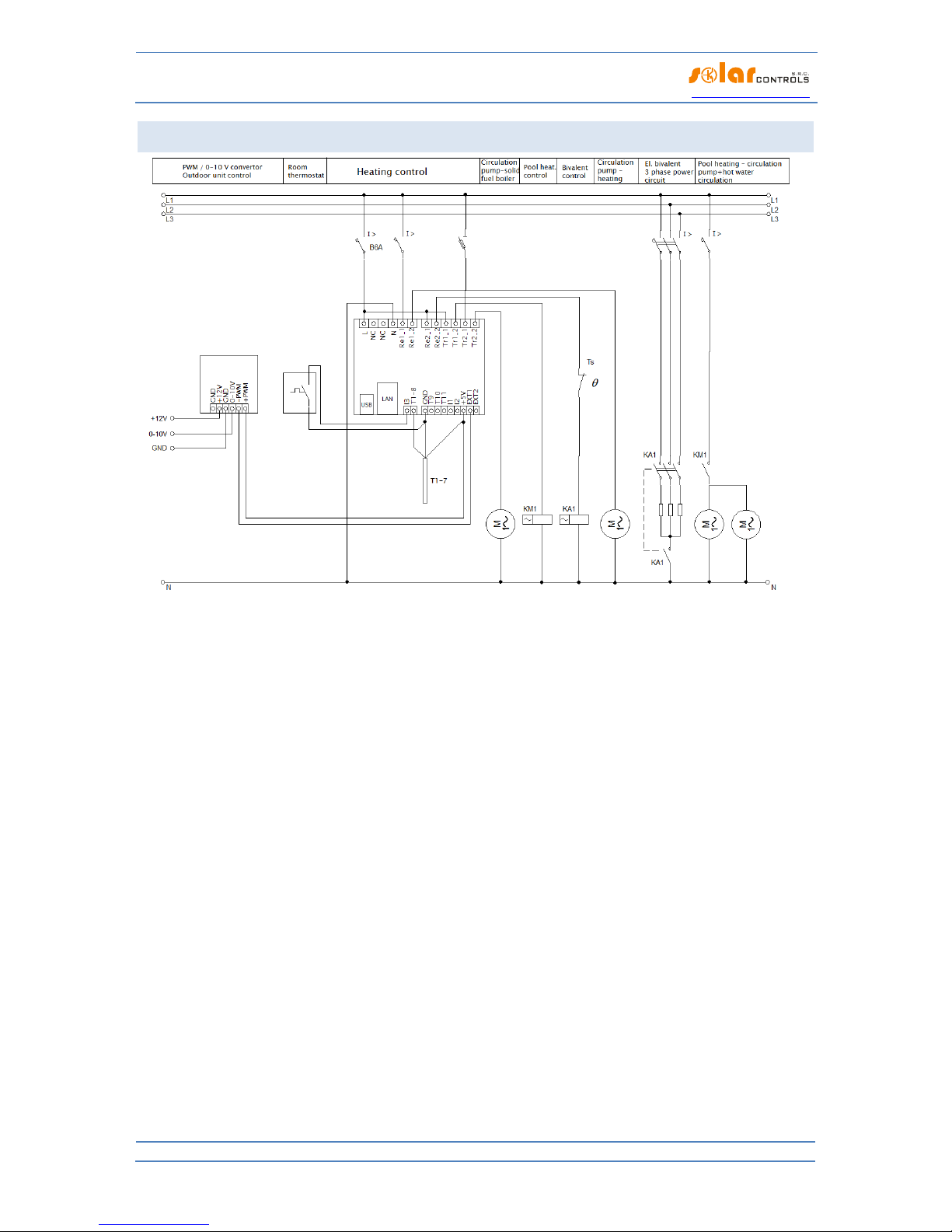
Connect the pumps, contactors, etc. to the Tr and Re outputs by means of conductors with a cross-section
corresponding to the input power of the connected equipment.
Figure 1: Description of the connectors and LEDs (a view from above).
Description of the controller terminals:
L –controller power supply, 230VAC/50Hz (it must be always connected)
N –neutral conductor (it must always be connected)
Re1 –relay output 1 –terminals 1 and 2
Re2 –relay output 1 –terminals 1 and 2

Heating control - user manual
www.solarcontrols.cz
Instructions for the installation and setup of the device
Page 8 of 58
Tr1 –triac output 1 –anodes A1 and A2
Tr2 –triac output 2 –anodes A1 and A2
Ext1- –external output 1 –negative electrode (open collector)
Ext2- –external output 2 –negative electrode (open collector)
GND –negative electrode for connecting digital and analog temperature sensors and digital inputs
+5V –positive electrode for external outputs and the power supply of digital temperature sensors
I1 –digital input 1
I2 –digital input 2
I3 –digital input 3
T1-8 –data bus for digital temperature sensors T1-8
T9 –analog input for analog temperature sensor T9
T10 –analog input for analog temperature sensor T10
T11 –analog input for analog temperature sensor T11
An unmarked terminal is not connected (NC)
USB –USB interface connector (USB B)
LAN –Ethernet interface connector (RJ45, 10/100 Mbit/s)
Micro SD slot –it is located inside the controller and reserved for future use
Description of LEDs:
PWR –LED indication of controller power supply (green)
COM –LED indication of communication via the USB interface (yellow)
ERR –LED indication of an error status (red)
Tr1 –LED indication of activity of triac output 1
Tr2 –LED indication of activity of triac output 2
Re1 –LED indication of activity of relay output 1
Re2 –LED indication of activity of relay output 2
Ext1 –LED indication of activity of external output 1
Ext2 –LED indication of activity of external output 2
RJ45 connector –indication of Ethernet interface connection (left LED –carrier frequency, right LED –
connection speed)
The controller may be connected only in alternating power distribution networks with 230 V AC,
50 Hz parameters. The controller must be protected with a circuit breaker of the recommended
B6A size, the connected equipment and/or appliances must also be appropriately protected!
During assembly, the power supply leading to the point of assembly must be switched off
(distribution board)!
We definitely recommend that devices which are likely to cause a current overload or a short
circuit in the case of a fault and which are connected to the triac outputs should be protected by
fuse links for protecting semiconductors, e.g. a PV510 6A gR fuse with an OPV10 isolating switch
from the company OEZ, rather than by standard circuit breakers. We inform you that a warranty
complaint cannot be lodged if the triac outputs have been damaged by an overcurrent or short
circuit. A similar rule also applies to solid state relays if they are connected to external outputs.
Pay attention to the correct connection of the solid state relays in accordance with the user
manual.
Connect the controller according to the sample connection configurations in the below given figures:
Configuration A: an outdoor unit of a heat pump with an electrical bivalent system, an add-on solid
fuel boiler, a storage tank, hot service water heating, heating and pool heating

Heating control - user manual
www.solarcontrols.cz
Instructions for the installation and setup of the device
Page 9 of 58
Configuration B: an outdoor unit of a heat pump with a gas bivalent system, an add-on solid fuel
boiler, a storage tank, hot service water heating, heating and pool heating
Configuration C: an outdoor unit of a heat pump with an electrical bivalent system, a storage tank, hot
service water heating and heating (minimum effective configuration)
Configuration D: an outdoor unit of a heat pump with an electrical bivalent system, a storage tank, hot
service water heating, heating, in combination with the management of excess energy from the
photovoltaic power station by means of the WATTrouter M.
If the basic principles are observed, the connection can be combined in various ways. Various numbers of
devices can be connected to any outputs, various number of analog and digital temperature sensors, etc.

Heating control - user manual
www.solarcontrols.cz
Instructions for the installation and setup of the device
Page 10 of 58
CONFIGURATION A
Figure 2: Electrical diagram of configuration A. A PAST®storage tank is used; the heat sources primarily include an outdoor unit of a heat
pump with direct condensation in the tank and a bivalent electrical heat source and also a solid fuel boiler without its own electronic
control; heat consumers include flow heating of hot water in the tank, one heating circuit with classic radiators and one heating circuit
for heating the pool by means of a pool heat exchanger. The power of the outdoor unit is controlled by a 0-10 V signal via a PWM/0-10V
converter. The temperature of the heated premises is controlled by a room thermostat with PI control. The circulation pump of the solid
fuel boiler is switched on directly by the controller, the same applies to the circulation pump of the heating circuit. The circulation
pumps of the pool heating circuits are switched on by the KM1 auxiliary relay. The bivalent heat source in the storage tank is switched
on by the KA1 4-pole contactor, which at the same time switches off all work conductors on the basis of protection by an independent
mechanical Ts thermostat mounted in the upper part of the storage tank (ČSN EN 60335-1). A total of 7 digital temperature sensors are
connected.

Heating control - user manual
www.solarcontrols.cz
Instructions for the installation and setup of the device
Page 11 of 58
Figure 3: Simplified heating diagram of configuration A. The yellow letters refer to explanatory notes of the function blocks, the blue
letters refer to explanatory notes of the temperature sensors. The outdoor unit of the heat pump is connected to the exchanger in the
storage tank by means of the refrigerant distribution in the direct condensation mode. The temperature of hot service water is
controlled automatically by a thermostatic mixing valve and it does not have to be controlled by the controller in any way. A
thermostatic valve for heat offtake for the radiators is not essential, nevertheless it enables a small continuous heat offtake from the
top part of the tank into the heating system. We always place the outside temperature sensor out of the flow of air cooled by the
outdoor unit.
Blocks:
A –PAST® storage tank
B –outdoor unit of the heat pump
C –solid fuel boiler
D –circulation pump of the solid fuel boiler
E –cold water input
F –hot service water output
G –thermostatic mixing valve
H –circulation pump of the heating circuit
I –radiators
J –circulation pump of the pool heating circuit
K –pool heat exchanger
L –circulation pump of the pool water
M –pool
N –expansion tank
Temperature sensors:
1 –solid fuel boiler –heating water input
2 –solid fuel boiler –heating water output
3 –storage tank –bottom of the tank
4 –storage tank –middle of the tank
5 –storage tank –top of the tank
6 –pool heat exchanger –pool water input
7 –outside temperature sensor

Heating control - user manual
www.solarcontrols.cz
Instructions for the installation and setup of the device
Page 12 of 58
CONFIGURATION B
Figure 4: Electrical diagram of configuration B. A PAST®storage tank is used; the heat sources primarily include an outdoor unit of a heat
pump with direct condensation in the tank and a bivalent gas boiler and also a solid fuel boiler without its own electronic control; the
heat consumers include flow heating of hot water in the tank, one heating circuit with classic radiators and one heating circuit for
heating the pool by means of a pool heat exchanger. The connection differs from configuration A only in replacing the electrical bivalent
system with a gas boiler. The switching of the gas boiler can always be done directly by means of a relay output of the controller
because this output is potential-free. If the gas boiler manual prescribes a requirement for switching by a potential-free contact, only
relay output Re1 or Re2 can be used, the triac and external outputs cannot be used!
Figure 5: Simplified heating diagram of configuration B. The explanatory notes are identical with configuration A. Block O refers to the
gas boiler.

Heating control - user manual
www.solarcontrols.cz
Instructions for the installation and setup of the device
Page 13 of 58
CONFIGURATION C
Figure 6: Electrical diagram of configuration C. A PAST®storage tank is used; the heat source is an outdoor unit of a heat pump with
direct condensation in the tank and a bivalent electrical heat source; heat consumers include flow heating of hot water in the tank and
one heating circuit with classic radiators. The explanatory notes are identical with configuration A.
Figure 7: Simplified heating diagram of configuration C. The explanatory notes are identical with configuration A.

Heating control - user manual
www.solarcontrols.cz
Instructions for the installation and setup of the device
Page 14 of 58
CONFIGURATION D
Figure 8: Electrical diagram of configuration D. This configuration demonstrates the interconnection of the Heating Control device with
the WATTrouter M system thanks to which the outdoor unit of the heat pump can be used not only for meeting the present heating
needs but also for the very advantageous transformation of excess energy from the photovoltaic power station into heat. The diagram is
based on the connection of configuration C. Heating Control communicates with the WATTrouter by means of the LAN network (the
interconnection is indicated with a bold line only schematically, in practice it will probably always be solved via an external network
router or switch so that both devices can be monitored and configured). The figure also shows two more heating coils connected to the
triac outputs of the WATTrouter. These heating elements are used for the utilization of the excess energy in the storage tank when the
outdoor unit of the heat pump is not in operation or when the excess energy is higher than the present input power of the outdoor unit.
Only 2 coils of the usually three-phase cartridge are shown in the figure, but it is also possible to use a third coil if we connect it, for
example, to the SSR output of the WATTrouter through the solid state relay. When choosing the power supply phases of the individual
heating elements, we should pay attention to the rules specified in the WATTrouter handbook and we must also take into account the
size of the main circuit breaker and the input power and the number of phases of the outdoor unit of the heat pump (contemporaneity).

Heating control - user manual
www.solarcontrols.cz
Instructions for the installation and setup of the device
Page 15 of 58
Figure 9: Simplified heating diagram of configuration D. The explanatory notes are identical with configuration A. Block P refers to a
three-phase electrical cartridge heater used as a bivalent heat source and block R refers to a three-phase electrical cartridge heater
intended for using the excess energy by means of the WATTrouter. This cartridge heater is located in the bottom part of the storage
tank so that most of the tank volume can be used for the accumulation of the excess energy.
CONNECTION OF THE OUTDOOR UNITS OF THE HEAT PUMPS
Figure 10: Electrical diagram showing the connection of the controller with a single-phase Fujitsu outdoor unit via the UTI-INV-XX
control module from the company Impromat Klima s.r.o. The connection of a three-phase unit is analogous, see the installation
handbook for the device. Caution: This diagram is illustrative, it is necessary to always perform the connection according to the
installation handbook for the control module of the outdoor unit, the connection may change!
Figure 11: Electrical diagram showing the connection of the controller with the single-phase Mitsubishi outdoor unit via the PAC-IF011B-
E control module. The proper function of the connection requires the correct setting of the DIP switches according to the documentation
for this module. The KA1 relay is used for unblocking the operation of the unit on terminals 1 and 2 of the TB142 connector, it must be
done in this way by the break contact. In order to operate KA1 we will use the “Status duplicate 1” block (EXT1 -> Tr2). Terminals 3 and 4
of the same connector are permanently connected which makes the unit firmly set in the heating mode. The connection of a three-
phase unit is analogous, see the installation handbook for the device. Caution: This diagram is illustrative, it is necessary to always
perform the connection according to the installation handbook for the control module of the outdoor unit, the connection may change!

Heating control - user manual
www.solarcontrols.cz
Instructions for the installation and setup of the device
Page 16 of 58
OTHER CONNECTION OPTIONS
Figure 12: Expansion of the number of power outputs by means of a solid state RGS1A relay with direct-current control, from the
manufacturer Carlo Gavazzi, connected to the EXT1 and EXT2 outputs. Other SSRs with similar parameters (see the Chapter “Technics”)
can also be used. The outputs cannot be actuated by the fast PWM mode in this case, but only in the relay (ON/OFF) mode! Standard
relays or contactors cannot be connected to EXT1 and EXT2 outputs!
FINISHING THE ASSEMBLY
After finishing the assembly, carefully check the connection of the controller. In particular, check
the connection of terminals GND, T1-8, T9, T10, T11, I1, I2, I3, +5V, EXT1 and EXT2, that is, of all
terminals located in the bottom part of the controller to which the mains voltage or voltage
outside the tolerance values specified in the technical specifications MUST NOT be connected! It
is not allowed to connect equipment or appliances with input power higher than the maximum
allowed input power! Equipment with consumption higher than 1 A MUST NOT be connected to
outputs Tr1 and Tr2! NO loads may be connected to the reserved terminals! Failure to observe
this rule will almost certainly result in damaging the controller and losing the warranty!
The heating distribution and refrigerant distribution must be prepared by a professional
plumbing company so that the entire installation will be secured against possible accidents. This
warning primarily concerns the correct installation of pressurized valves and safety mechanical
thermostats. In the case of the storage tank installation, it is necessary to observe the relevant
safety warnings. The controller itself does not solve and even cannot solve all accident states!
If your computer is connected via a USB cable ALWAYS USE ONLY ONE USB port on the controller.
Otherwise the USB interface in the controller may be damaged!
After a careful inspection of the controller connection, switch off the circuit breakers/fuse cutouts of the
connected equipment and switch on the main circuit breaker and also the circuit breaker of the controller. The
LED PWR (power supply indication) will light up. If it fails to light up or if the light is not ON continuously or if
the LED ERR (error status) starts to flash, proceed according to the Chapter “Troubleshooting”). No output is
active in the default state and no connected equipment will therefore be switched on.
The controller is installed now and ready for setup.
L1
T1
A1+ A2-
RGS1A23D..
T9
T10
T11
I3
T1-8
GND
EXT2
+5V
EXT1
I2
Re2_1
Re2_2
L
N
NC
I1 Tr1_1
Tr1_2
Tr2_1
Tr2_2
Re1_1
Re1_2
NC
USB
LAN
I >
B6A
L L
N N

Heating control - user manual
www.solarcontrols.cz
Instructions for the installation and setup of the device
Page 17 of 58
DEVICE CONFIGURATION
In order to configure the device you will need a laptop or possibly a standard PC (placed close enough to the
controller) and a USB interface and connection to the computer network by means of the Ethernet, Wi-Fi, etc.
(hereinafter referred to as the computer). The configuration is done by means of the controller web interface.
The first configuration of the network usually has to be done through the USB interface by means of the HC
downloader program which can be downloaded from the manufacturer’s website. You can find the description
of the program in the Chapter “HC downloader”. After the first configuration, you can use any mobile device
which runs a modern web browser supporting the HTML5 standard.
If it is not possible to proceed further in the configuration due to any reason, follow the instructions in the
Chapter “Chyba! Nenalezen zdroj odkazů.”.
CONFIGURATION OF THE CONNECTION TO THE CONTROLLER
Heating Control allows monitoring and configuration exclusively by means of the Ethernet port. In order to
start the communication it is necessary to configure the network connection correctly.
Always have the network and the controller access configured by a person with the appropriate
qualifications. The manufacturer does not provide any technical support for the problems
associated with the network configuration, except in the case of a provable malfunction of the
network interface of the controller.
It is advisable to carry out the first configuration of the network in the controller through connection to the
USB interface by means of the HC downloader software (in the case of connection via the Ethernet port the
connection will almost always be lost after a change of the parameters).
Knowledge of your local network parameters is the basis for a successful configuration. It is necessary to know
this data:
the IP address of your router, or possibly of another access point to your local network (if it is
installed),
the free range of IP addresses, i.e. addresses which do not belong in the range of dynamically assigned
addresses in the case of the switched-on DHCP server and at the same time they are not static
addresses of other devices in your local network,
the subnet mask of your local network which is used by all devices connected to it.
The controller allows only the configuration of the static IP address. The controller does not support dynamic
assigning mainly due to common use, i.e. access from the Internet via the network router and its NAT function
which practically requires a permanent address of the controller in the local network.
CONFIGURATION OF THE CONNECTION TO A LOCAL NETWORK
The network connection is configured in the “Settings” tab in the “Network settings” group.
Caution: The network setting will only be effective after the controller has been reset (the option
“Reset unit on config. write”)!
IP address: Set the IP address in such a way that it will not collide with another device in your local
network. For example, if the address of your router is 192.168.2.1, you can set 192.168.2.10 if this
address does not already belong to another device in your local network and if this address does not
lie in the range of the dynamically assigned addresses of the DHCP server in your local network (it is
usually active in your router). The default IP address in the controller is 192.168.2.201.

Heating control - user manual
www.solarcontrols.cz
Instructions for the installation and setup of the device
Page 18 of 58
Subnet mask: Enter the mask of your local network. In the overwhelming majority of cases the value is
255.255.255.0. This is also the pre-set subnet mask in the controller.
Default gateway: Set the IP address of the device which will be used for sending controller requests
outside the local network. In the overwhelming majority of cases it is the IP address of your router. In
the given example the address will be 192.168.2.1. This is also the pre-set IP address of the default
gateway in the controller. If you do not have such a device, enter a different unused IP address in your
local network. In this case, however, requests directed outside the local network will not be
acknowledged.
Controller MAC address: Enter the physical/MAC address of your controller. Change this value only if
there is another device with the same physical address in your local network.
Note: The Heating Control devices do not have their own address range registered within the IEEE. If
you change the MAC address, you must respect specific rules which apply to these addresses!
UDP port: Enter the value of the UDP port to which UDP communication from the HC downloader
program will be directed. We recommend that you change this value only if there are more UDP
servers in your local network (which should be accessible from the Internet) or if you wish to improve
the protection of the connection. If you change the UDP port in the controller, it is also necessary to
change the UDP port settings in the configuration of the connection driver via LAN/UDP of the HC
downloader software. The default value pre-set in the controller is 50000.
HTTP port: Enter the value of the HTTP port where the controller will listen to requests of the HTTP
protocol, i.e. of the web interface. We recommend that you change this value only if there are more
web servers in your local network (which should be accessible from the Internet) or if you wish to
improve the protection of the connection. The default value pre-set in the controller is 80.
CONFIGURATION OF THE INTERNET CONNECTION
In order to connect to the Internet it is recommended that you have an active global static IP address. If you
have only a dynamically assigned IP address, this address can be found from the settings of your router. A
dynamic IP address can be also used, but depending on the Internet connection provider this address can
change with varying frequency. Therefore, if the controller is not accessible from the Internet, always check the
global WAN network configuration in your router first.
The controller can be accessed from the Internet only through routers or other access points which include the
NAT function (Native Address Translation) or another similar function, which is used for translating IP
addresses into the local network.
The following text describes a sample Internet connection configuration using the Zyxel P660 router for both
TCP and UDP protocols. The procedure is as follows:
Click to open the drop-down list “Service name”in the “Network/NAT/Port forwarding” tag and
select the “User Define” item.
Fill in the row in the routing table according to the figure and press “Apply”, this will write the setting
in the router.
Repeat the procedure for both rows of the table (protocol TCP and UDP).
The setting of the NAT function is similar for other routers.

Heating control - user manual
www.solarcontrols.cz
Instructions for the installation and setup of the device
Page 19 of 58
If your global (static or currently used dynamic) IP address is, for example, 80.200.50.6, then simply enter
http://80.200.50.6:8080 in your web browser (we recommend that you create a bookmark in the browser) in
order to access the controller from the Internet by means of the HTTP protocol.
SETTING OF THE CONTR OL FUNCTIONS
The setting of the controller consists of several steps of varying significance –the setting of inputs, outputs,
activation and the setting of function blocks and other presets.
After the web interface has been displayed in the browser, we can proceed to set the temperature
inputs. If the temperature inputs are connected to the controller, the relevant temperatures and
green indicators signalling the function of the sensor should already be shown. If more sensors
(especially digital sensors) are used, we will probably not recognize at first sight which sensor belongs
to which function and therefore we will proceed in the following way for every sensor:
a) we will heat the sensor by touching or in another way
b) according to the change in temperature in the web interface we will find out which sensor it is
and we will write the caption on the right side next to the sensor designation (T1-11).
If all physically connected digital sensors are not shown or if we have other doubts, we will use the
button “Search for digital temperature sensors” in the “Settings” tag. The controller will again try to
find the available sensors on the bus.
Caution: If we add or remove a digital sensor, the function “Search for digital temperature sensors”
will order the sensors according to internal priorities and therefore after every such change it will be
necessary to check the assignment of the captions to the sensors and the assignment of the sensors to
the individual control blocks (see point 4)!
Immediately after completing the configuration, we will write the assigned captions in the controller
by means of the button “Write”.
We proceed in an analogous way when setting the digital inputs. If we do not remember the
connection, it will be necessary to activate the input temporarily, this will switch on the blue indicator
of the input connection and we will be able to assign a caption. After finishing the configuration, we
will again write the assigned captions in the controller by the button “Write”.
When setting the outputs, we can use the “Output test” function in the “Settings” tab. Before doing
so we should, however, again check the connection of the outputs according to the instructions
specified in the Chapter “Instructions for Installation of the Device”.We will test the individual
outputs and assign the captions. After completing the configuration of the outputs, we will again write
the assigned captions in the controller with the “Write” button.
After setting the inputs and outputs, we can proceed to the activation and setting of the individual
control blocks. Every block is activated by a ticking box located on the left next to the name of the
block, e.g. on the left next to the text “Heat pump 1” in the “Heat pumps” tab. By ticking this box the
entire block will change its colour and the configuration field will become open to changes. In
addition, it is necessary to assign the inputs and outputs in every block; this is done by means of drop-
down menus designated as “Input –xxx”or “Output –xxx”. In the drop-down menus the inputs and
outputs are already designated with captions, it is therefore advisable to have all the inputs and
outputs designated appropriately before starting the configuration of the blocks. A control block will
not work correctly or it will not work at all, if it is not activated and if incorrect inputs and outputs
have been assigned. The same input and output can be assigned to 2 or more drop-down menus in
different control blocks, in the case of the output the resulting state is then a logical sum (function
OR), or possibly in the case of the actuation of the output in the PWM mode (see the note below) it is

Heating control - user manual
www.solarcontrols.cz
Instructions for the installation and setup of the device
Page 20 of 58
a maximum (function MAX), of the function output of the relevant control blocks. After we have
assigned the inputs and outputs, we can change other configuration fields of the control block if the
default values do not suit us, and in the end we will again write the block configuration in the
controller with the “Write” button.
Note: All outputs can be actuated by two states (ON/OFF) or in the PWM mode. In the case of the external
Ext1 and Ext2 outputs this actuation will cause fast PWM at the output with the carrier frequency of 200
Hz, in the case of other outputs slow PWM with the carrier frequency of 0.002 Hz (it corresponds to the
period of 500 s). The manner of actuation depends on the configuration of the individual control blocks.
After the configuration of the control blocks, we can change the general options in the “Settings” tab,
for example connection with the WATTrouter, low tariff signal source, setting of the outside
temperature, etc. We will again write these changes in the controller with the “Write” button.
In the “Statistics” tab it is possible to change the loading period of the online chart and to select values
which should be monitored. We will again write these changes in the controller with the “Write”
button.
Save the configuration on the computer disk with the “Save” button. It can be loaded again by means
of the “Open” button. Due to the security restrictions of browsers, saving is usually allowed only in the
folder designated for downloading (“Downloaded items”, etc.).
DESCRIPTION OF WEB INTERFACE ITEMS
This chapter describes all items of the controller web interface in which all values and states of inputs, outputs
and other operational values are shown clearly and the states and settings of the control blocks are shown in
the individual tabs.
The web interface is implemented by means of the AJAX/XML technology, Javascript must therefore be allowed
in the web browser.
Authorization of the data write in the controller is not performed by means of the common cookies standard
but by sending access data directly in the data of every request for data writing. This mechanism simplifies the
implementation in a superior whole, where work with cookies could be problematic.
MEASURED QUANTITIES AND STATES
Digital temperature inputs:
T1-8 –input designation.
Name field –it shows an input caption and makes it possible to enter this caption. The text can have a
maximum of 16 characters in the ASCII code.
Status indicator –green light if the sensor is connected and working.
Value –it shows the measured temperature in tenths of °C.
Analog temperature inputs:
T9-11 –input designation.
Name field –it shows an input caption and makes it possible to enter this caption. The text can have a
maximum of 16 characters in the ASCII code.
Status indicator –green light if the sensor is connected and working.
Value –it shows the measured temperature in tenths of °C.
This manual suits for next models
2
Table of contents
Popular Heating System manuals by other brands

Danfoss
Danfoss SET2E Installation & user's instructions

Valeo
Valeo spheros thermo 230 Workshop manual

Viessmann
Viessmann Vitotronic 200 Series Operating Instructions for the System User

ThermoSoft
ThermoSoft NeverFreeze SX-0810-24 manual

Vallox
Vallox 132 E Series Technical specifications

York
York AFFINITY DEZ024 Technical guide

Steffes
Steffes ThermElect Hydronic 9150 Owner's and installer's manual

Dimplex
Dimplex Quantum quick start guide

BrookVent
BrookVent aircycle ONE 100 Installation, maintenance & user manual

Vectaire
Vectaire WHHR100DC-B Plus Installation, operating and maintenance instructions

VOKERA
VOKERA Linea User instructions

Inta
Inta HIPER II Installation and operating manual