Sears Gamefisher 298.586192 User manual

VIODEL NO.
298:586192
Iowner's
responsibi)ity
•maintenance
•operation
•trouble
shooting
1, replacement
parts
=blication No. _....
_7-45560-206

TABLE OF CONTENTS PaBeNo.
SPECIFICATIONS ••........................ i
OWNER'S RESPONSIBILITY .... _ ......................... .... 2
MAINTENANCE .......................................... , 4 _
LUBRICATION GEAR HOUSING .............................. 4
MUFFLER" INSPECTION .................................... 4
_' PROLONGED-STORAGE 4
OPERATIONS . •
NEW:AUTOMATIC CLUTCH ., ............................... • 4
BOAT MOUNTING ..................... :....... 5
,STEERING ADJUSTMENT ................................. 5
2-CYCLE ENGINE FUEU MIXTURE ........ :. ............... . 6 :
STARTING PROCEDURES .................. :.............. 6_i
STOPPING PROCEDURES , ................. -.............. 6
FLOODING. ; .............. :......... .................... 7
CARBURETOR ADJUSTMENTS ........ -. ..................... 7
PROPELLER SHEAR PIN .................................. 7
IGNITION SYSTEM "_",.......... • 8
REMOVING MOTOR FROM BOAT .......................... 8
SALT WATER OPERATIONS ..... • ......................... 8
TROUBLE SHOOTING CHECK LIST .......................... 9
REPLACEMENT PARTS .................................... I0
ORDERING PROCEDURES ......................... Outside Back Cover
PRODUCT WARRANTY ........................... Outside Back Cover
SPECIFICATION
Type of Engine ........................... Air Cooled 2-Cycle
Horsepower .......................................... 3.00
Maximum RPM .................................... 7500
Weight .................. (11 kg) ........ 24.3 Lbs. Approx.
Bore and Stroke ........... (41 rnm x 38ram) .... 1.61" x 1.50"
Displacement ............. (50 cc) ............... 3.05 cu.in.
Fuel Capacity-Engine Tank .... (1.3 liters) ............. 1-1/5 qt.
ignition ....... Flywheel Magneto with Transisterized Electronic Ignitor.
Spark Plug .................... NGK BMR-6A or Champion RCJ-8
Spark Plug Gap Setting ....... (0.6 mm) ................. 025"
Bearings (Engine) Ball
Bearings (Gear Hsg.) ........ ................ Ball& Oilite Bronze
Starter ................... ...................... Recoil
Propeller Dia. and Pitch ...... (182 mmx 130 ram} .. 7.17" x 5.12"
Lub. (Gear Hsg.) .................................. SAE 90
Fuel Mixture ... 50 to 1 ratio of regular grade gasolineto 2-cycle outboard
lubricant or its equivalent BIA certified TC-W 2-cycle outboard lubricant.
Steering _""
243 P,vot Steering

IMPORTANT
Owner's Responsibility and Operating Safety Check List
BE SURE TO READ AND DO THE FOLLOWING BEFORE
OPERATING YOUR OUTBOARD MOTOR
SAFETY CHECK LIST
1, Learn and observe the boating laws of the U,S, Coast Guard, state, local author-
ities.
2, U.S. Coast Guard regulations require the following:
a. Provide an approved life-vest, type 1,2 or 3, Personal Flotation Device for each
person in boat. (Encourage passengers to wear them.)
b. If the boat exceeds 16 feet. also carry a type 4, throwable Personal Flotation
Device.
3. 0o not fill fuel tank with motor running or near any flame or lighted smoking
material.
4, When loading boat distribute the load evenly, keep the load low; don't overload;
don't stand in a small boat. Take weather and water conditions into account.
5, Do not permit persons to ride on parts of the boat not designed for such use.
Standing, bow riding and seat back or gunwale riding can be especia}ly dangerous.
OWNER'S RESPONSIBI LITY
6. Read owner'-s manual before running your new outboard motor_
7. Before starting, make sure your motor is securely mounted to boat transom with a
•: safety chain. Tighten clamp st_Jd handles securely by hand.
B. Be sure to have pliers, screwdriver, spa=respark plugs, wrench, shear Pins and cotter
}ins in boat whenever leaving shore.
9. Be sure 1;ohave an adequate supply of fue_ (carry only in an approved container) on
board. Use a good grade of regular gasoline with proper mixture, as cited in the
Specifications.
10, Occasionally check to be sure clamp stud handles on transom mounting bracket are
tight.
11, IN CASE OF AN EMERGENCY, THE ENGINE CAN BE STOPPED BY DEPRES- ._
SING THE STOP BUTTON (IF SO EQUIPPED) OR PLACING CHOKE KNOB IN
:FULL CHOKE POSITION.
12, Keep an alert lookout, Serious accidents have resulted from failure to use eyes.
13. Keep firefighting and lifesaving equipment in good condition and readily accessible
at all times.
14. Good housekeeping is eve_ more important afloat than ashore. Cleanliness dimin-
ishes the probability of fire and tripping hazards.
TIPS FOR TRAILERING OR AUXILIARY USE
15. When "launching or loading boat on a trailer, place your outboard motor in the
tilted storage position, Also when trailering your boat and outboard motor, keep
outboard motor in upright (vertical) position on the boat transom, Outboard
motors transported across rough roads in the "tilt" position could cause transom
damage=or mounting brackets to break off, losing your motor. If motor must be
trailered in "'tilt '_ position, a short length of 2 x 4 should be placed between the
:motor bracket and the motor leg, The motor leg should then be firmly tied down
against the 2x 4 to prevent any possible damage. Simitar precautions should be
taken if using the motor as an auxiliary power source for a sailboat or power boat.
When using motor as an auxiliary power source, the use of an auxiliary adjustable
position motor bracket is recommended.
2

FuelFifler Cap -
andAir VentScrew---_
Step Button
FuelShul-olfValve
FuelSedimentBow!
and Filter
DualAutomaticClutchHousin
ReverseDrivingLock-
Till Pin Adjuslment
MufflerPipe
ExhaustOutlet
Propeller
Collar Pin
/
GearHousingCoVer_
Slader Handle
ChokeLever
PowerHead
SparkPlug
SteeringHandle
ClampStud Handles
Transom8rackel
DriveShaft Pipe
\
CavilalionPlate
Fill andDrain Plug
GearHousing
Figure l
MAINTENANCE
1, FEATURE INFORMATION
a. This outboard motor has_ special design
features as shown in Figure I.
b Your selection of our Marine Products will
provide you with many hours of enjoyable
boating, To assure your complete satisfac-
tion on 1he investment you have just made.
we ask you to read this manua! thoroughly
before going afloat. Acquaint yourself with
the particular areas of operation on your
outboard motor as you read the step-by-step
procedures. "Keep in mind maximum per-
formance _s achieved only when the owner
or operator is completely familiar with the
operating insTru;ctions
c Periodic servicing will be required, tt is
recommended that you consult your Sears
Service Center when service is necessary.
We will be happy to extend out facilities
•and assure prompt service.
BOLT -_
FILL AN-__
DRAIN PLUG_
COTTER P|N_
Figure 2
Figure 3'
HOUSING
COVER
_._ PROPELLR

(3)
(41
MAIN I !-NAN_;i:
2. LUBRICATION _GEAR HOUSING
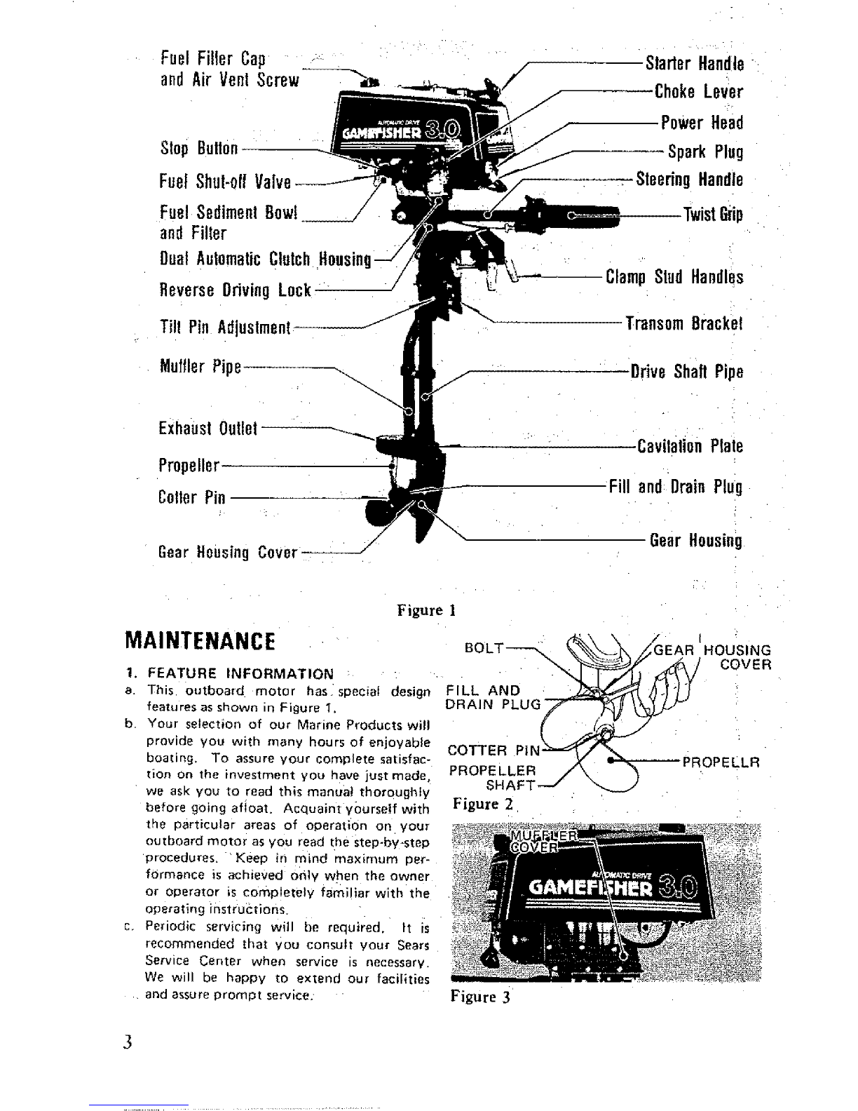
a. The Gear Housing has been pre.lubricated at
the factory; however, the grease level should
be checked as follows using SAE 90 out-
board motor grease, (See Figure 2).
(1) Prior to initial operation,
{2) After first four (4) hours of use,
(3) Recheck after every fifty (50) hours
running time.
{4) Replace with new lubricant at the end
of your outboard motor season, This
is important, as it removes any water
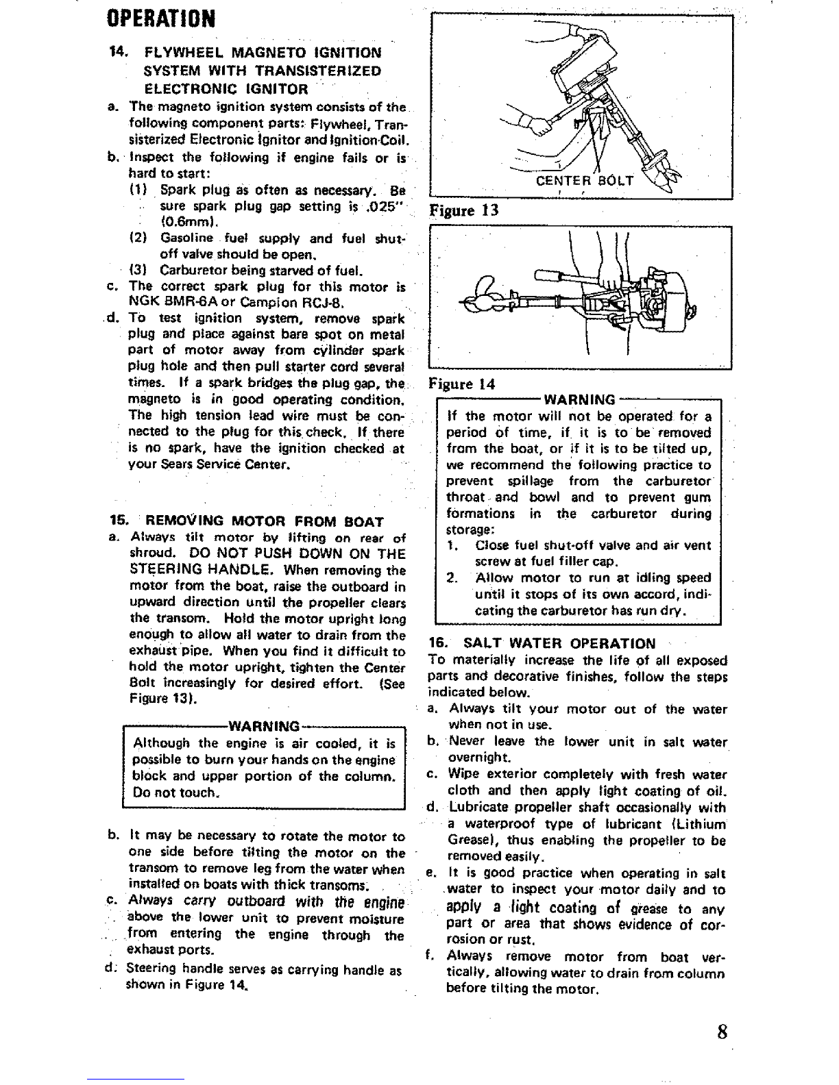
from the gear housing and prevents
possible corrosion to internal parts.
b. To Check, Drain or Fill gear housing, follow
these steps:
(1) Position outboard motor upright,
(2) Remove drain plug and washer, then
insert nozzle of gear lubricant tube
into h01e. .
Squeeze tube until lubricant is forced
out around tube,
Replace plug and washer. Be sure plug
is tightened securely.
':(5} To achieve complete drainage of.lubri-
cant, remove cotter pin, propeller and
:shear pin from propeller shaft, ale0,
gear housing Cover by unscrewing 2
bolts.
(6) When lubricant has completely "drained,
replace parts and refill gear housing
using filling procedu re above.
best results, lubricate propeller shaft
lithium grease every 30 to 60 days,
c. For
with
3. 'MUFFLER iNSPECTION : •
a.:. Periodically remove muffler cover by un-
screwing screws and inspect for carbon
build-up inside the muffler inlet and outlet.
the exhaust port and the combustion
chamber of the cylinder. Excessive carbon
will prevent drawing the maximum power
out of the engine. (See Figure 3L
b._ Care should be exercised While cleaning
_' away carbon to prevent scratches to the
surface of the engine components and drop-
ping carbon inside of crankcase.
b.
c.
(3) The outboard' m0tor" sh0uld :be
mounted on a stand vertically with
power head up for storage.
(4} Pull starter handle slowly until resist-
ance is fett due to compression pres-
sure, then stop. Release starter tension
slowly to prevent engine from revers-
ing rotation due to compression
pressure_ This position will close both
the intake and exhaust ports for
storage,
(5) Drain and fill gear housing as outlined
under Lubrication of Gear Housing.
(Ref. 2)
(6) Wipe exterior completely wiih fresh
water cloth and then apply light coat-
ing of oil,
When starting a new season, always use fresh
gasoline, Last year's gasoline may have
varnish deposits that will plug the carbu-
retor jets, thus requiring a complete over-
haul.
To plan for the coming season, we recom-
mend you contact your Sears Service
Center before the new season for any service
repair work required,
OPERMION
5, NEW AUTOMATIC CLUTCH
a. New automatic clutch. Based On a dual
centrifugal clutch design, it allows the out-
board prop to turn at very stow speeds or
even come to a complete stop while the
engine continues operating efficiently. It
eliminates the need to shift gears by hand
and prevents the engine from overheating
and stalling at slow speeds.
When engine starts, motor is neutral. As
throttle increases, sub clutch engages. At
:approx. 6 MPH, main clutch engages to
provide direct drive for cruising,
4. PROLONGED STORAGE
a. To store your outboard motor for pro-
longed storage, prepare outboard as fol-
lows:
(1) See paragraph on stopping procedures.
(Ref, 10)
(2) When removing outboard motor from
boat, allow all water to drain from
unit,
4

vI klIl'lI |Vl|
6. BOAT MOUNTING
a. Mount the motor on the center of the boat
transom (stern). (See Figure 4).
CAUTION
Hand tighten transom bracket and clamp
stud handles simultaneously. Oo not use a
wrench or any other device that would
cause damage to brackets. Occasionally
check to be sure lamp stud handles on
transom mounting bracket are tight.
(See Figure 5).
b. To obtain the best performance from your
outboard, the following boat transom speci-
fications are recommended: (See Figure 4),
Transom Angle {See View 3):
........... 12 to 15 degrees
Transom Height (See View 4): 20.7 inches
c. The angle of the motor column is easily
adjusted by removing the Hitch Pin and
changing the Tilt Lock Bracket Pin in the
five (5) different angle position holes
located on either side of the right or ieft
Transom Mounting Brackets. Each angle
position elevates five (5) degrees. Try
center hole position first. (See Figure 6),
d. To find the correct angle position, make a
test run at full throttle with your usual
loadil_g i'n the boat. Always stop motor,to
change the Tilt Lock Bracket Pin. The cor-
rect angle position will have your boat
traveling with the bow slightly higher than
the stern, but should not porpoise (bow
rises and fails rapidly and continuously). Be
sure Tilt Lock Bracket Pin is always pushed
completely through both Transom Mount-
ing Brackets and Hitch Pin is secured.
WARNING
If the motor column is tilted too far out-
ward, the boat is tikeiy to porpoise or
cavitate at full throttle, which can be
dangerous because across wind or a wave
could suddenly deflect the boat into a
dangerous turn. Also, if the motor
column is tilted too far inward, the bow
of the boat will,dig, in. which can be
dangerous when crossing a wake or in
rough water. Do not run motor in the
storage position. (See View I and2,
Figure 4).
e, Secure motor to boat with Safety Chain.
Chain not included with motor. •
Figure 4
• !
Figure 5
Figure 6
CS
• H "_ f
View 4
7. STEERING ADJUSTMENT
Tighten steering tension bott using a spanner
for desired steering effort.(See Figure 6).
CAUTION j
There is a possibility of losing bolt if
backed out too far,
5

OPERATION
8. 2-CYCLE ENGINE FUEL MIXTURE
Use a good grade of regular gasoline. (See mix-
ing table below.)
CAUTION
Always use BIA certified TC-W oil in the
50:I ratio. Failure to do so may result in
excessive spark plug fouling, piston
scoring, or bearing failure. Do not under
any circumstances, use multigrade, such as
10W-30, or other automobile oils.
If 81A certified oil is not available, use
an SAE 30 or 40 2-cycle or outboard oil,
We reserve the right to refuse warranty on
parts which are damaged when using
improper fuels or lubricants,
WARNING:
IGasoline is highly flammable. Always mix
in well ventilated area. Do not fill tank
with motor running, nor near any flame
or while smoking. Be sure vent screws
and filler caps on tanks are finge r tighte-
ned when transporting gasoline in the
trunk of your automobile to prevent
explosion.
Figure 7
Figure 7A
FUEl-
MIXING
_'ABLE
50:1
MIXTURE 1
U,S. Measure
Regular
Gasoline
In Gellons
1
3
56
Amount of oil
to be added
In Pints In Oz
0.16 2.6
0AS 7,7
0.80 12.8
0.96 15.4
......... - .....
Metric Measure
Regula_ [' Amount of oll
Gasoline to be added
In Liters In Liters
1 0.02 :
5 0.10
10 :0;20
"20 0.40
':9; STARTING PROCEDURE (See Fig.7 & 7A)
a,: Open air vent screw located on fuel filler
":: cap by turning counterclockwise.
b. Open fuel shut=off valve.
c. Open throttle grip to half throttle.
d. Move choke lever to "'On" position.
WARNING
When starting outboard, the boat will
move with a sudden burst of speed. Make
sure you are well seated so as not to lose
your balance with a fast start.
Figure 8
e. Pull starter handle slowly until you feel
starter engage. Then pull with rapid
motion and altow the starter cord to
retract slowly, (See Figure 8).
f. After engine has started, gradually move
choke lever to "Off" position while
warming up the engine.
g. Let engine idle for approximately 3
minutesbeforemoving t_rott|e grip tO
"Fast" position.
10. STOPPING PROCEDURE
To stop engine, move throttle grip to "Slow"
position and press stop button.(See Figure 7A)
6

OPERATION
WARNING
In case of' an Emergency, the engine can
be stopped by moving the Choke Lever to
Full Choke Position.
If the motor will not be operated for a
period of time, if it is to be removed from
the boa[, Or if it iS t0 be tilted up, we
recommend the following practice to
prevent spillage from the carburetor
throat and bowl and to prevent gum
formations in the carburetor during
storage:
1. Close fuel shut-off valve and air
vent screw at fuel fillercap.
2. Allow motor to run at idling speed
until it stops of its own accord,
indicating the carburetor has run
dry.
11. FLOODING
To clear engine of excess fuel, move choke lever
to "'Off" position and throttle grip to half
throttle position. Putl recoi1 starter handle
until engine-starts and continues to run.
12. CARBURETOR ADJUSTMENTS
a. Your motor has _idle adjusting screw and
the idle speed has been preset at the factory.
However. you maY need to adjust the idle
speed using Idle Adjusting Screw. Turn the
Screw clockwise to increase motor speed
and counter clockwise to decrease it. The
idle speed adjustment must be done with
throttle grip at fult dosed position and the
idle speed should be as low as 13ossibIe while
the eng ne runs steady. (See Figure 9)
b. Periodically Check filter for dirt by unscrew-
]ng Sediment Bowl, (See Figure 12)
13. PROPELLER SHEAR PIN & COTTER
PIN HOLDER
a. The Shear Pin is used for the purpose of
protecting the Drive Train and Gears. The
Shear Pin will not prevent the propeller
from becoming damaged when striking an
under water object. When shear\ pin is
broken, the engine will continue to run,
however, the propeller will not be rotating.
CAUTION I
Stop engine immediately after shearing
pin to avoid possible damage to the engine.
b. To replace shear pin, shut off motor,
remove cotter pin with pliers and slip off
propeller. (See Figures 10& tl).
c. Replace with new shear pin located in shear
pin and cotter pin holder. (See Figure 12).
Figure 9
SLOW
/--- IdleAdjustingScrew
Figure 10
Figure 11
Figure 12

OPERATION
14. FLYWHEEL MAGNETO IGNITION
SYSTEM WITH TRANSISTERIZED
ELECTRONIC IGNITOR
a. The magneto ignition system consists of the
following component parts: Flywheel Tran-
sisterized EJectronic ignitor and ignitionCoil.
b, Inspect the following if engine fails or is
hard to start:
(1) Spark plug as often as necessary. Be
sure spark plug gap setting is .025""
(0,6ram).
(2) Gasoline fuel supply and fuel shut-
off valve should be open.
(3) Carburetor being starved of fuel.
c. The correct spark plug for this motor is
NGK BMR_6A or Campion RCJ-8,
d. TO test ignition system, remove spark
plug and place against bare sPot on metal
part of motOr away from c_ilinder spark
plug hole and then pull starter cord several
times. If a spark bridges the plug gap, the
magneto is in good operating condition.
The high tension lead wire must be con-
nected to the plug for thischeck. If there
is no spark, have the ignition checked at
yOur Sears Service Center.
15. : REMOVING MOTOR FROM BOAT
a. Always tilt motor by lifting on rear of
shroud. DO NOT PUSH DOWN ON THE
STEERING HANDLE, When removing the
motor from the boat, raise the outboard in
upward direction until the propeller clears
the transom. Hold the motor upright long
enough to allow all water to drain from the
exhaust Pipe. When you find it difficult to
hold the motor upright, tighten the Center
Bolt increasingly for desired effort. (See
Figure 13).
............. WARNING
Although the engine is air cooled, it is
possible to burn your hands on the engine
block and upper portion of the column,
Do not touch.
b. It may be necessary to rotate the motor to
one side before tilting the motor on the
transom to remove leg from the water when
installed on boats with thick transoms; ,
c. Always carry outboard with ttle engine
above the lower unit tO prevent moisture
.from entering the engine through the
exhaust ports.
d; Steering handle serves as carrying handle as
shown in Figure 14.
Figure13
Figure 14 WARNING
if the motor will not be operated for a
period of time, if it is to be removed
from the boat. or if it is to be tilted up,
we recommend the following practice to
prevent spillage from the carburetor
throat anct bowl and to prevent gum
formations in the carburetor during
storage:
t. Close fuel shut-off valve and air vent
screw at fuel filler cap.
2. Allow motor to run at idling speed
until it stops of its own accord, indi-
cating the carburetor has run dry.
16. SALT WATER OPERATION
To materially increase the life of all exposed
parts and decorative finishes, follow the steps
indicated below.
a, Always tilt your motor out of the water
when not in use.
b, Never leave the lower unit in salt water
overnight.
c. Wipe exterior completely with fresh water
cloth and then aPply light coating of oi!.
d. Lubricate propeller shaft occasionally with
a waterproof type of lubricant (Lithium:
Grease), thus enabling the propeller to be
removed easily.
e, It is good practice when operating in salt
.water to inspect your-motor daily and to
apply a light coating of grease to any
part or area that shows evidence of cor-
rosion or rust,
f, Always remove motor from boat ver-
tically, allowing water to drain from column
before tilting the motor,
8

TROUBLESHUUiiN5 (;lll:t;r_ Llbl
*Take your outboard motor into any one of over
2000 SeersSe_ice Units.
×X Fuel Tank Empty .... • .... ,....
X X Fue! Shut.Off Valve Closed
x X X X Fuel Line Kinked or Pinched
X X X Fuef Filter Dirty or C!ogged
! .....................................
XX X X Vent Screw on Fuel Tank Filter Cap Closed
×X X X Carburetor PassagesCloggedor Di_y
X X X X X incorrect Fuel-0il Mixture
X X X X X j Carburetor Out of Adjustment
X_X : IEngine Flooded ....
--_[ Xx' x x i Wro_gTypes"_kPlog ....................
"_I X [ "x x x i, Defect_veorFouiedSparkPt'u'g " _...... ;
X X Oefective Magneto
X " Engine Out of Time
"-_ : X i X :X................... i Transisterized:Etectrooic.......... Ign,,!,torout0 fo,[der = , ,.......
xxxxxWeak Ignition Co11
X X Spark Plug Lead Wire Not Secured
X..... X: Frayed or Cracked LeadWlre {nsu
REPLACEMENT PARTS
FOR
MODEL No.298,586192
10

FIG. 1 ENGINE
29-
33.... I f
80
5
81
24
25
--26
7
7
66 65
48
11

FIG.I ENGINE
!REEN&
: 1-00!
!-002
1-003
!-004
1-005
1-007
1-_008
1-000
1-010
l-oil +
1-012
1-014
!-015
1-017
1-024
1-024
1-024
1 -:024
1-025
1-026
1-027
1-020
1-030
1-031
1-032
1-033
1-038
1-039
1-040
1-041
1-048 -
1-055
1-005
1-ON8
! -ON?
1-068
1:'074
,1-075:
1-078
1-079
!-080
1-0St
1-085
1-080
P.P.No.
ozB-zozol-zoz
z57-o4ooo-ooo
018-00540-200
002-10200-003
017-]0200-202
041+10100-201
030-02000-201
031_-10t00-210
037-10100-200
040-10242-800
o0e-o2000-2oo
099-6162o-30o
999-66173-000
990*02101-004
071-02007-216
071_02007-220
071-02000-230
071-02007-240
09U-01020-200,
999-60153-000
090-10200-202
072-10242-010
107-21854-800
198-05015-800
155-2|?17-B01
112-10201-200
902-01100-011
991-09100-001
178-0130H-800
202-10200-201
lgB-ItlOG-200
256-01046-200
G90-11050-102
002-01050-041
090=11000-302
992-10080-042
9g0-11040-182
992-I0040=042
090-1|060-252
902-10060-042
992-10060-042
990-11066-142
692-01050-041
990-11050-102
PARTS NAME
CYLINDER ShrOUD
SPAKX PLOO CAP ASS'Y -
SPARE PLUg BM2BA
CYLI_D_X CORP.
CYLIHDEZ GASKET
PISTOn R|ng
PISTo_'PIN, CIeCLIP
PISTOB .
PiSTOn PIN IOX35 :
CRANK S_AFT CORP.
FOOD-RUfFKEY 3XISXG
BALL _gARINQ 10203
OIL SEAL 10307
NEEOLg BEARIng PIOIOB
CNAHK SHAFT SNIX 0.10
CRANK SHAFT SHIR 0.15
CLANK SHAFT'$HIM 0,20
CRANK SBAFT SHIN 0.30
BALL BEARIng 16202
OIL SEAL 15307
CRANKCASE GASKET
CBANK CASE ASS'Y
ZOXITIOa COIL CORP.
CORD CLA_P CONP,
HAOHETO ROTOX COHP.
YAH CASE
VASNER 10
HUT 10 (L.E, TBR£AD)
STOP CORD COXP,
QZO_H£T'
COAD CLAHP L
SPARK PLUO RUBBER COYER B
SC2EV 5X10
rASHER 5
SCREV 6X30
S.VASBEE6
$CXEV 4Xt8
S.VASHER 4
SCREV 6x25
S,VASnE2 0
S.VASnER B
SCRER BXlB
VASHER 5
SCREW SXIO
O'ty
I
l
1
!
l
2
2
!
!
1
!
1
l:
x
Y
¥
V
V
I
1
!
1
1
1
!
!
!
I
!
|
1
1
2
2
4
4
2
2
4
4
,(
4
2
2
/

FIG.2 TANK, CLUTCH & MUFFLER
102
15
56
55
16
79 :
23 30
28
45 44 :43 42
31 6261
34 __-41
13

REENo.
2-002
2-003
2-004
2-005
2-000
2-007
2-008
2-009
2-010
2-011
2-012
2-013
2-014
2-015
2-016
2-017
2-016
2-019
2-020
2-021
2-022
2-023
2-024
2~025
2*020
2-027
2-02E
2-029
2-030
2-031
2-033
2-034
2-035
2-036
2-037
2-038
2-039
2-040
2-04t
2-042
2-043
2-044
2-045
2-046
2-047
2-048
2-049
2-050
2-052
2-053
2-054
2-055
2_056
2-059
2-060
2-061
2-062
2-063
2-064
2-005
2-060
2-067
2-068
Z-ODD r
2-070
2-071
2-072
2-073
2-074
2-075
2-076
2-077
2-078
2-079
2-100
2-101
2-102
2-103
2-.104
P.P.No.
i595-35100-902
i630-35500-200i
300-35505-200
305-35500-200
659-00801-200
H29-10201-201
790-10201-210
783-t0200-202
793-10200-201
401-35500-200
603-02101-803
853-1021B-UO0
654-10201-201
965-34501-200
055-10201-200
655-0141A-200
592-10201-900
594-00517-200
700-15008-118
700-14509-140
580-01004-200
021-35100-201
206-00503-203
170-I0218-B00
160-01004-200
181-01004-200
403-02000-201
393-02500-201
080-03113-200
410-10201-900
i347-01046-201
210-35300-800
358-I0112-200
290-10112-802
359-10112-203!
1357-10112-204
342-10205-220
992-01100-011!
991-00100-001
737-10100-200
716-10201-200
73?-10201-200
717-t0201-2001
221-35500-200i
226-35500-200 _
220-35300-200
225-35500-2001
227-35500-200i
990-11050-452
992-10050-042
992-00050-041
9D0-II050-122:
992-I0050-042i
991-01060-021!
992-10050-012
990-11040-302
992-10040-042
990-11080-202
992-I0060-042
990-11040-122
992-10040-042
990-11050-122
092-10050-042
090-11060-252
992-10060-042
990-I]050-122
992-10050-042
992-01050-041
990-11060-121
992-00050-011
012-35500-200
011-35100-200
702-30200-200
60t-35590-900
330-35555-200
331-35555-200
i906-35555-200
336-35118-200
992"10060-012
PARTS NAME. O'ty
TANK CXP ASZ'Y 1-
TAME CAP 9ASXET 1
EHGtHE COVEI (SEARS) I
CDSRIOB ROBBgR 1
COLLAR 4
STAHTER FAVL BASE 1
STAETER PAVL SPBIR6 2
STARTER PAUL
STEP BOLT 2
FUEL TAXK l
FUEL TARE BAHO CONF. 2
FUEL TAKE BEACKET CORP. 1
FUEL TAHR BRACKET 91
TAME SUPPORT EOBBEH El
FUEL TAE[ CUSHIOH RUBHER 2
FUEL TAME CUSHIOH RUBEHR 2
PET-COCK ASS'Y l
PET-COCK FIXIHG HOT 1
FUEL PIPE 5XEXI16 1
PU_L PIPE 4.SX$XZ40 t
CLIP 8 2
PIU HOLDER 1
STOP BUTTON COVER t
STOP BHTTO_ COUP, 1
STOP BDTTOH PIXIHO HUT 1
SPECIAL S.VASHER 1
INLET MANIFOLD GASKET 1
IRLET HAHIFOLO I
CLIP 7.5 1
AIH CLEAHER ASS'Y l
CLUTCH FLAHGE 1
CLUTCH SPHIHU COKP, 3
CLUTCH UASBER A 3
CLUTCH ATH COHF. 3
CLUTCH RASHER E 3
CLUTCH STEP BOLT 3
CLUTCH 3PRIHG 3
LASHER IO "'" "" _.,i, I
HUT 10 (L.H, THREAD) 1"
MUFFLER UASXET 1
RUFFLER BODY At
MgFFLEH GASKET 1
RUFFLER BODY 91
HUFFLER PIPE OASKET 1
MUFFLER PiPE STAY A1
EUFPLER PIPE 1
HUPPLEH PIPE BRACKET A l
KUFFLER PiPE _RACKET B1
SCREV 5X45 4
S.UASHEE 5 4
HASHER 5 4
SCREW 6X12 2
S.VASHER 62
HUT 9 : .2
S.VASHER 6 2
SCREW 4X30 2
S.VASHER 4-12
SCEEV 0X20 2
S.VASHER 6 2
SCREV 4XI2 T
S,VASHEH 4 7
SCEEV 5X12 .2
$.VAS_ER 5 2
SCHEH 6X25 i!
S.VASHEE 6 I
SCREV 5X12 '3
S.VASHER 5_" 3
WASHER 5 3
SCREV 6X12 3
SMALL WASHER 5 '2:
SBRAm PIH ..... 2
COTTER PIH 2
FUEL PIPE COIL .1
HOSE CLAMP A$S'Y ', l
EIGHT SIDE.HARE (SEARS) 1
LEFT SIDE XARK (SEARS) 1
RAME PLATE (SEALS) 1
STARTER EAR_ (SEARS) I
S,VASHHE 6 314

FIG.3 RECOIL STARTER
O--
13
12
S
11 • •
r------ 19
17
15
J_ ...............
REF.No. P.P.No.
3-_oo 7_8-iozo_:o0oi
3-00! 772-10207-200
3-002 774-10200-200
3-003 779-I0200-203
3-009 783-01006-201i
3-011 780-10201-200i
3-012 785-10207-201
3-013 833-I0207-200i
3:014 992-0t040-011i
3-015 773-10200-200i
3-017 990-11050-251
3-018 77E-10200-200i
3-019 827-IOE00-201i
3-020 990-11050-122i
3-021 992-10050-042i
3_O22 992-01050-041
3-023 902-10050-042
3-024 99t-41050-022
3-026 786-10200-200
3-030 791-IOR00-200
+
PARTS '
RECOIL STARTEE-ASS'Y
RECOIL STARTER BODY:
STAETEI ROPE REEL
RECOIL SPRIEQ
STAITEE ROPE
EOPE GOIDE
STARTER IANDLE
STARTER EAEDLZ CAP
RASHER 4
PULLEY SEA_TIOUTER
SCIEV 5XE5
RECOIL SPRING cAsE
RECOIL SPRING HOLDER
$CREV 5X12
S.IASHER S
VA$1ER5
S.WASHEE 5:
CAP MOT 5
STARTER YASXER
STARTER _USHIHG"
NAME iQ'ty
1
i
1
1
l
!.
:1
1.
1
i1
I
1
2
2
1
1
1
1
I

FIG.4 CARBURETOR
7-r
11--_ 8-_
io__,
f
38 12 I
_----27 /r
_4o
r
I REENo.
!'' 4-oo'o....
4-002
4-003
4-004
4-005
4-000
4-007
4-008
4-0]0
4-011
4-012
4-016
4-017
4-021
4-024
4-026
4-027
4-028
4-020
4-030
4-03I
4-037
4-038
4-039
4-040
P.P.No. PARTS NAME
455-20217-900
507-20110-200
595-20200-200
504-20202-200
619-20202-200
503-20202-200
592-2002T-920
59Z-2005T-200
623-21700-200
622-20217-200
561-20202-900
807-20110-200
599-2001T-740
608-20202-200
994-34040-100
605-20202-200
_03-20400-200
628-20202-200
804-20110-200;
620-20202-200
627-20406-200
571-20200-200
602-20420-200
S96-20202-200
598-2005T-950
CARBURETOR ASS'Y
CABLE ADJUSTER
bODY CAP
THROTTLE VALVE SPRIHG
TXROTTLE SPRING SEAT
JET HEEDLE CLIP
JET HEEDLE ASS'Y 004
THROTTLE VALVE 0,HXl. H
AOJDST SPRZHG
ADJUST SCRE¥
OUTLET CLIP ASS'Y
FLOAT CHAHHER GASEET
HA|N JET 174
FLOAT CHAMBER ¥/TEREAD
SCREV 4X10/S
CHOKE PIH
REEDLE VALVE
FLOAT ARH
FLOAT
DRAIH SCREV GASKET
DRAIH PLUG
HAH[FOLD SEAL
_EEOLE SEAT
CALE AOJUSTER LOCK HOT
[HEEDLE JET ,2005
O'ty
i
1l!
1
1
I
1
I
]
1
1
I
!
!
16

ri_.:) HANDLE & BRACKET
41 2O 35
52
0
•54 45
4O
27
33
32
31 37
17

rm_.: rlAI'iULR & BKAGK|[
REF.No, P.P,No. PARTS NAME
5-000 870-'35552-G00 T_'IST GRIP A$S:Y"
5-00! H85-01058-800 T,ROTTLE VICE COHP.
5-005 200-35300-800 CLOTCfl DRUN COHP.
5-006 _903-51042-002 STOP RIHG C42
5-007 999-6_B00-404 BALL DEARIHG sOOO4DD
5-008 993-50020-002 STOF RING C20
5-009 185-35300-204 CLUTCH CASE
5-0]0 990-21000-252 fleX. BOLT 6X25
5-011 902-10000-042 $.VASHER B
5-012 990-11050-202 SCREH 5X20
5-013 992-10050-04E S,VASNER 5
5-014 161-35500-202'_ANGLE STOPPER
5-015 793-10200-201 STEP BOLT
5-016 092-04080-031 HAVE BASHE_ 8
5-017 160-35552-800 STEERING HAHDLE COHP.
5-019 !52-35500-200 HAHOLE HASHER
5-020 990-21080-302 BOLT 8X30
B-021 992-01080-04! HASHER 8
5-022 OOl-OIO80-021 HOT 8
H-OE3 992-10080-042 S.VASHER 8
5-024 134-35500-20! THRUST BASHER
5_025 I15-35300-210 NKACKET
5-028 131-35306-200 TflRUST BRACKET
5-027 !38-35500-201 RETURN CAM
5-028 990-21060-102 BOLT H_IO
5-029 990-11050-162 SCHEV 5XIH
5-030 992-I0050-042 S.HASHER B
5-031 137-35500-201RETURX CAN GUIDE
5-032 138-35500-201RETURH GUIDE PLATE
5-033 992-!0050-042 S.MASHER 5
5-034 990-11050-122 SCREH 5XI2
•5-Q35 139_35500-200 BETURH SPBIBG
5-036 129-35100-200 BRACKET PIN STOPPER k
5-037 123-35500-201 BRACR£T PIH S
5-038 107-351i8-801CLAHP BRACKET 8 COHP.
5-0301 10_-35t19-801CLAHP BRACKET ACOHP.
5-040 990-21050_T52 BOLT 6X75
5-041 108_3550'1_200 CLAMP B_ACEET BUSEIHG
5-042 991-41080-022 CAP HUT 6
5-043 992-10060-042 S,VASHER
5-044 992-0t060-041 BASHER 6
_5-Q45' 871-35552-200 THROTTLE GKIP
5-046 87E-35552-200 THROTTLE IH_ER PIPE
5-047 873-35552_200.THROTTLE BOLDER A
5-043 874-35552-200 THROTTLE BOLDER B
5-049 875-35552-EOOjTHBOTTLE HOLDER COVER
5-050 878-35552-200 gIBE GUIDE
5-051 879-35552-200 TkPPIHG SCREV
5-052 990-t]050-202 SCHEN 5X20
5-033 991-01050-021 HUT 5 -'
5-054 877-35'552-200 THROTTLE STOPPER
5-055 87e-35532-200 THROTTLE STOPPER SPRIH6
B-05B 903-32201-200 RIBE CLAMP BAND
I
O't)
1
1
!
!
!
!
!
2
4
1
1
1
1
2
1
I
1
1
I
I
4
!
I
1
I
4
4l
l
l
l
l
!
2
l
1
I
I
I
l
!
!
2
E
2
!l
!
18

FIG.6 DRIVE SHAFT PIPE &GEAR CASE
30
29
23
14
17
18
36
20 ....
22
21
6
13¸
19
Table of contents
Other Sears Outboard Motor manuals