Seaside Communications DCT 6200 HD User manual

HDTV Capable
USB 1.1VIDEO IN
SMART CARD
L AUDIO IN R
INFO
MENU
POWER
A/B
GUIDE
SELECT
in teractive d igital communicati o n s
Digital Cable Box
USER MANUAL
DCT 6200 HD
Wiring Instructions
Additional Information
Seaside TV

WARNING
TO REDUCE THE RISK OF FIRE OR SHOCK, DO NOT EXPOSE THIS
APPLIANCE TO RAIN OR MOISTURE.
CAUTION
TO PREVENT ELECTRICAL SHOCK, DO NOT USE THIS (POLARIZED) PLUG
WITH AN EXTENSION CORD, RECEPTACLE, OR OTHER OUTLET UNLESS
THE BLADES CAN BE FULLY INSERTED TO PREVENT BLADE EXPOSURE.
The lightning flash with arrowhead symbol, within an equilateral triangle, is
intended to alert the user to the presence of uninsulated “dangerous voltage”
within the product’s enclosure that may be of sufficient magnitude
to constitute a risk of electric shock to persons.
The exclamation point, within an equilateral triangle, is intended to alert the
user to the presence of important operating and maintenance (servicing)
instructions in the literature accompanying the appliance.
CAUTION
RISK OF ELECTRIC SHOCK
DO NOT OPEN
REFER SERVICING TO QUALIFIED SERVICE PERSONNEL.
TO REDUCE THE RISK OF ELECTRIC SHOCK,
DO NOT REMOVE COVER (OR BACK).
NO USER-SERVICEABLE PARTS INSIDE.
CAUTION:
Graphical Symbols and supplemental warning marking locations on bottom of terminal.

1Read instructions
All the safety and operating instructions should be read before the digital cable box is operated.
2Retain instructions
The safety and operating instructions should be retained for future reference.
3Heed warnings
All warnings on the digital cable box and in the operating instructions should be adhered to.
4Follow instructions
All operating and use instructions should be followed.
5Cleaning
Unplug this product from the wall outlet before cleaning. Do not use liquid cleaners or ae rosol
cleaners. Use a damp cloth for cleaning.
6Attachments
Do not use attachments not recommended as they may cause hazard.
7Water and moisture
Do not use this equipment near water; for example, near a bathtub, wash bowl, kitchen sink, or
laundry- tub, in a wet basement, or near a swimming pool, and the like.
8Accessories
Do not place this product on an unstable cart, stand, tripod, bracket, or table. The product may fall
causing serious injury and serious damage to the appliance. Use only with a cart, stand, tripod,
bracket, or table recommended by the manufacturer, or sold with the equipment. Any mounting of
the appliance should follow the manufacturer’s instructions, and should use a mounting accessory
recommended by the manufacturer.
9Ventilation
Slots and openings in the cabinet are provided for ventilation and to ensure reliable operation of
the equipment and to protect it from overheating. The openings should never be blocked by
placing the product on a bed, sofa, rug, or similar surface. Equipment should never be placed near
or over a radiator or heat register, or in a built- in installation such as a bookcase or rack unless
proper ventilation is provided.
10 Power sources
This product should be operated only from the type of power sources indicated on the marking
label. If you are not sure of the type of power supplied to your home, consult your local power
company. For equipment intended to operate from battery power, or other sources, refer to the
operating instructions.
11 Ground or polarization
This equipment may be equipped with a polarized alternating - current line plug (a plug having one
blade wider than the other). This plug will t into the power outlet only one way. This is a safety
feature. If you are unable to insert the plug fully into the outlet, try reversing the plug. If the plug
should still fail tot, contact your electrician to replace your obsolete outlet. Do not defeat the
safety purpose of the polarized plug.
12 Alternate warnings
This equipment may be equipped with a 3 - wire grounding - type plug , a plug having a third
(grounding) pin. This pin will only t into a grounding - type power outlet. This is a safety feature. If
you are unable to insert the plug into the outlet, contact your electrician to replace your obsolete
outlet. Do not defeat the safety purpose of the grounding - type plug.
13 Power cord protection
Power supply cords should be routed so that they are not likely to be walked on or pinched by
items placed upon or against them, paying particular attention to cords at plugs, convenience
receptacles, and the point where they exit from the appliance.
IMPORTANT SAFETY INSTRUCTIONS

IMPORTANT SAFETY INSTRUCTIONS
14 Outdoor Cable Grounding
Ensure the cable system is grounded as to provide some protection against voltage surges and
built-up static charges.
15 Lightning
For added protection for this equipment during a lightning storm, or when it is left unattended and
unused for long periods of time, unplug it from the wall outlet and disconnect the cable system.
This will prevent damage to the video product due to lightning and power line surges.
16 Overloading
Do not overload wall outlets and extension cords as this can result in a risk of re or electrical
shock.
17 Object and liquid entry
Never push objects of any kind into this equipment through openings, as they may touch
dangerous voltage points or short -out parts that could result in a re or electrical shock. Never spill
liquid of any kind on the product.
18 Servicing
Do not attempt to service this equipment yourself, as opening or removing covers may expose you
to dangerous voltage or other hazards, return to Seaside Communications for replacement.
19 Safety check
Upon completion of any service to this digital cable box, ask the Seaside service technician to
perform safety checks to determine that the product is in proper operational condition.
20 Heat
This digital cable box should be situated away from heat sources such as radiators, heat registers,
stoves, or other products (including ampliers) that produce heat.

This Class B digital apparatus meets all requirements of the Canadian Interference - Causing
Equipment Regulations. Cet appareil numérique de la classe B respects toutes les exigences du
Règlement sur le matériel brouilleur du Canada.
www.ic.gc.ca/eic/site/ic1.nsf/eng/home
www.ic.gc.ca/eic/site/ic1.nsf/fra/accueil
CANADIAN COMPLIANCE

Motorola, Inc. www.motorola.com
MOTOROLA and the Stylized M Logo are registered in the U.S. Patent and Trademark Ofce.
All other product or service names are the property of their respective owners. © Motorola, Inc. 2010
Disclaimer
The information in this document is carefully examined, and is believed to be entirely reliable. However, no
responsibility is assumed for inaccuracies. Furthermore, Seaside Communications reserves the right to make
changes herein to improve readability, function, or design.
Motorola Computer Software Copyrights
The Motorola product described in this manual may include copyrighted Motorola computer programs stored
in semiconductor memories or other media. Laws in the United States and other countries preserve for
Motorola certain exclusive rights for copyrighted computer programs, including, but not limited to, the
exclusive right to copy or reproduce in any form the copyrighted computer program. Accordingly, any
copyrighted Motorola computer programs contained in the Motorola products described in this manual may
not be copied, reproduced, modied, reverse-engineered, or distributed in any manner without the express
written permission of Motorola. Furthermore, the purchase of Motorola products shall not be deemed to grant
either directly or by implication, estoppel, or otherwise, any license under the copyrights, patents or patent
applications of Motorola, except for the normal non-exclusive license to use that arises by operation of law in
the sale of a product.

a`qSOMM rëÉê dìáÇÉ
1
TABLE OF CONTENTS
Overview ...................................................................................................................................................... 3
DCT6200 Components........................................................................................................................... 3
Remote Control....................................................................................................................................... 6
Getting Started ............................................................................................................................................ 7
Connecting your DCT6200 ......................................................................................................................... 8
Video Options ......................................................................................................................................... 8
Connecting Your DCT6200 to an HDTV .................................................................................................... 9
Video Connections ................................................................................................................................. 9
Audio Connections ............................................................................................................................... 11
Audio Connections for an A/V Receiver ............................................................................................... 12
Connecting your DCT6200 to an HDTV and D-VHS ............................................................................... 13
Connecting your DCT6200 to a Standard Definition Stereo TV ........................................................... 14
Connecting your DCT6200 to a Standard Definition Stereo TV and Stereo VCR ............................... 15
Connecting your DCT6200 to a Standard Definition Stereo TV and Mono VCR................................. 17
Connecting your DCT6200 to an A/V Receiver, Standard Definition TV, and Stereo VCR ............... 18
Connecting your DCT6200 to a Standard Definition Stereo TV, Mono/Stereo VCR,
and DVD ..................................................................................................................................................... 21
Setting Up Your New DCT6200 for Digital Cable Services ................................................................... 22
Activating Your DCT6200 ..................................................................................................................... 22
Calling Your Cable Operator for Authorization ..................................................................................... 23
Optimizing Your HDTV Picture ............................................................................................................. 24
Recording Your Connections .................................................................................................................. 26
Operation ................................................................................................................................................... 27
Turning Power On and Off.................................................................................................................... 27
Changing Channels .............................................................................................................................. 27
Adjusting the Volume............................................................................................................................ 27
Interactive Program Guide.................................................................................................................... 27
On-Screen Graphics ............................................................................................................................. 27
Important Information About the 4:3 Override Feature......................................................................... 28
Closed Captions ................................................................................................................................... 28
Resetting the User Settings.................................................................................................................. 28

2
Data Devices .............................................................................................................................................. 29
User Options.............................................................................................................................................. 30
Troubleshooting........................................................................................................................................ 32

DCT6200 User Guide
OVERVIEW
The Motorola DCT6200 High Definition Cable Receiver for Seaside
digital cable, and high definition (HD) programming.
The DCT6200 offers the following standard features:
• Interactive digital cable receiver - enables both standard and HDTV programming
• Integrated high definition decoder with YPbPr component video output
• Digital Visual Interface (DVI) connector
• PCM, AC-3, Dolby Digital® and Dolby Pro Logic® audio capability
• 54-860 MHz tuner
• Full feature access from front panel
• LED display with IR receiver for Seaside remote control
The following items are included with your DCT6200:
• Seaside Universal Remote control with batteries
• Coaxial cable
• Audio (Left/Right) cables
• Component (YPbPr) video cables
3
4
TO
TV/VCR
CABLE
IN
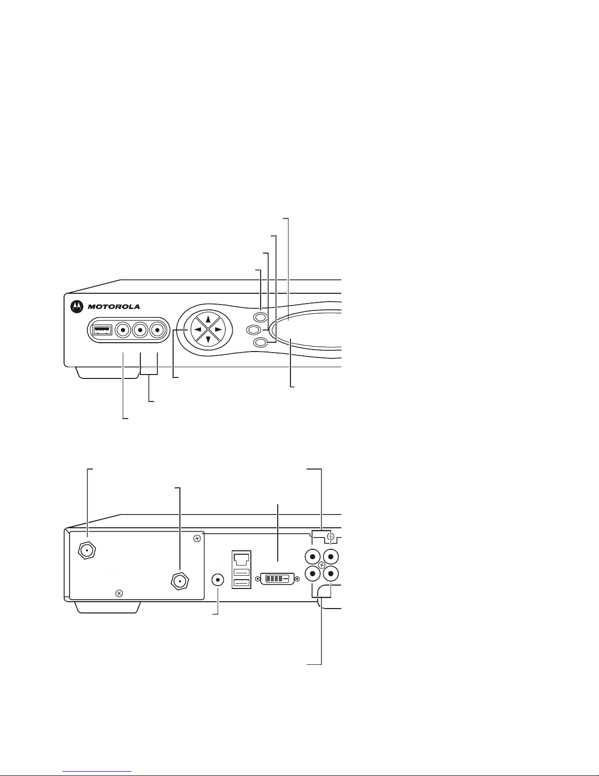
FRONT PANEL
A
UDIO IN (R/L)
A
UDIO IN (L/R)
POWER switch
INFO switch
MENU switch
A
UDIO OUT (R/L)
Connects to audio input of a stereo receiver or TV
Connects to a CD player or stereo tuner
Connects to a CD player or stereo tuner
Turns the DCT6200 on or off
Displays current channel and program information
Displays the menu area
VIDEO IN
Connects to baseband video output of a
VCR, camcorder, or other video device
DVI
TO TV/VCR
Connects DCT6200
to a high definition TV
Connects to TV or VCR
CABLE IN
Connects to cable signal
from your service provider
IR
Enables DCT6200 to control a VCR
while recording a selected program.
(Not supported by all program guides).
INFO
MENU
POWER
C
U
R
S
O
R
MSGS.
ON
USB VIDEO IN L AUDIO IN R
CURSOR
Moves cursor around pro
g
ram
guide and menu screens
POWER
indicator
Li
g
hts to indicate
DCT6200 is on
Message Indicator
Li
g
hts when a messa
g
e is waitin
g
AUDIO OUT
AUDIO IN
R L
IR DVI-D OUT
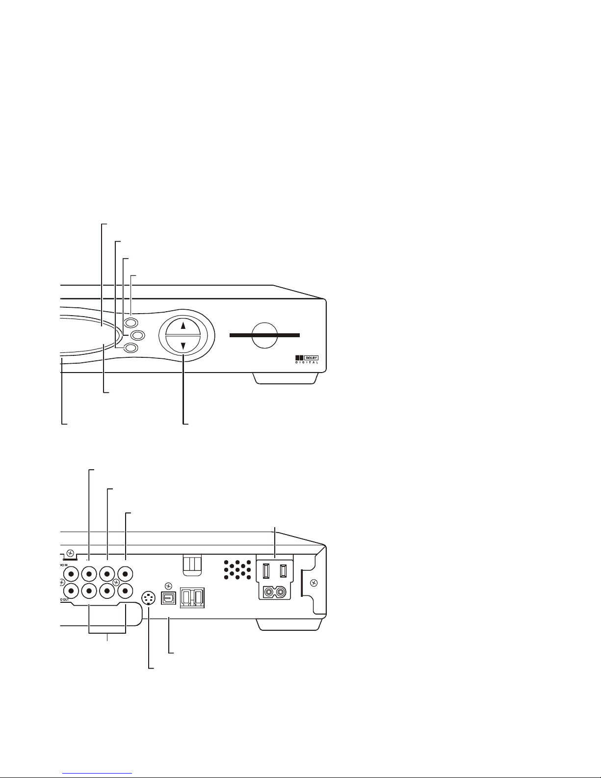
Provides Dolby Digital 5.1 audioor PCM audio®
SPDIF
CHANNEL
A/B Indicator
SELECT switch
A/B switch
GUIDE switch
Lights, if optional switch is activated
Selects menu options
Manually enables RF bypass function (optional)
Displays the program guide
Scrolls down or
up through the
channels
VIDEO IN*
VIDEO OUT
Connects to baseband video output from
a VCR, camcorder, or other video device
Delivers video to an external
device, such as a TV or VCR
Y Pb Pr
C Switched Outlet
Delivers component video
to an HDTV
S-Video
Connect to S Video input of TV or VCR
OPTICAL SPDIF
Provides Dolby® Digital 5.1 audio or PCM audio
Connect AC power cord from
another device, such as a TV or VCR
A/B
GUIDE
SELECT
C
H
A
N
N
E
L
SMART CARD
REMOTE
A/B
Display
Displays channel number
and time of day
BACK PANEL
REMOTE
indicator
Lights to indicate
remote control
is in use
VIDEO
IN OUT
S-VIDEO
OPTICAL
SPDIF
SPDIF
Y Pb Pr
L
5

Remote Control
The DRC 450 remote control provides basic control of the DCT6200, TV, VCR, DVD, and audio
devices. For programming instructions and remote codes, refer to the DRC 450 User Guide
included with your remote control.
noitpircseDyeK1 AUDIO, VCR/DVD, CABLE, OR TV
Selects a device to control.
2 HELP
Displays the help screen (if supported by program guide).
3 POWER
Turns the currently selected device on or off.
4 PAGE � PAGE �
Pages through menu screens and program guide.
5 EXIT
Exits a menu or program guide.
6 CURSOR
Moves the cursor around the program guide and menu screens.
7 OK/SELECT
Selects menu options, VOD, Pay-Per-View events or programs
from the program guide.
8 GUIDE
Displays the program guide.
9 VOLUME + VOLUME -
Increases or decreases the volume of the currently selected
device.
10 A / B / C
Functionality is determined by your service provider.
11 NUMBER KEYS
Use to directly select a channel.
12 TV/VCR BYPASS or A/B
Use to manually enable the RF bypass function. Requires a
cable-ready TV to operate. (Not available on all units.)
13 STOP, PAUSE, PLAY, REW, RECORD, F.FWD
Controls cable Video On Demand (VOD), VCR, or DVD player.
14 MUTE
Toggles the sound on and off.
15 LOCK/PPV
Use to limit viewing of selected programs.
16 INFO
Displays the current channel and program information. (Not
supported by all applications.)
17 MENU
Displays the main menu.
18 LAST
Recalls the last channel or returns to the previous menu screen.
19 CHANNEL + CHANNEL -
Changes the channels up or down.
20 FAVORITE
Displays preset favorite cable channels.
AUDIO
HELP
LOCK
PAGE
EXIT INFO
MENU
PAGE
VCR/DVD CABLE
POWER
TV
OK
LAST CHANNELVOLUME
A
1
4
7
TV/VCR
REW
STOP
DAY
B
2
5
8
0
C
3
6
9
ENTER
FFWD
PAUSE
RECORD
PLAY
DAY
FAVORITE
11
10
9
8
7
6
5
4
3
2
1
14
15
16
17
18
20
19
21
12
13
21 ENTER/MUSIC
Displays digital music channel menus.
6

a`qSOMM rëÉê dìáÇÉ
7
GETTING STARTED
Before you connect your DCT6200, be sure to review the following:
• Disconnect power from the DCT6200 before connecting or changing cable connections.
• For basic cable connections, use 75-ohm coaxial cables equipped with F-type connectors.
• A coaxial cable is provided to connect the DCT6200 to your cable wall outlet. A component video
cable and left/right audio cables are also provided to connect the DCT6200 to your TV.
• If you are connecting a coaxial cable from the TO TV/VCR connector on the DCT6200 to the coaxial
CABLE/ANTENNA IN connector on the TV, you must tune your TV to channel 3 or 4 to view the
DCT6200 output. Connecting the DCT6200 in this manner will remove its high definition video
output capability.
CAUTION!
Do not place anything on top of the DCT6200, especially other home entertainment components. Be sure to
provide adequate ventilation to prevent overheating.

8
CONNECTING YOUR DCT6200
This section describes how to connect the DCT6200 to your home entertainment system. Instructions and
diagrams are included for the following connections to the DCT6200:
• High Definition Television (HDTV)
• A/V Receiver
• HDTV and D-VHS Digital VCR
• Stereo TV
• Stereo TV and Stereo VCR
• Stereo TV and Mono VCR
• A/V Receiver, TV, and Stereo VCR
• Stereo TV, Stereo or Mono VCR, and DVD
Video Options
Before connecting your TV to the DCT6200, you must determine which type of video connection to use.
The DCT6200 offers five different video options. The options, listed in order from highest to lowest video
quality, are:
• DVI
• IEEE 1394
• Component video (YPbPr)
• S-Video
• Video (also referred to as composite video)
To determine whether your TV features DVI, IEEE 1394, component video, S-Video, or composite video,
check the manual supplied with your TV to determine the best connection available.
High definition video can only be viewed with DVI, IEEE 1394, or component video connections.
DVI, IEEE 1394, and component video allow you to view both high definition (HD) and standard TV
programming. Composite video and RF coaxial connections allow you to view only standard definition TV
programming.
If your TV has a DVI input, connect to the DVI-D connections on your DCT6200 instead of the IEEE 1394
or component video connections (Y, Pb, and Pr connectors).
If your TV doesn’t have a DVI input but does have an IEEE 1394 connector, connect to the IEEE 1394
connection on your DCT6200 instead of the component video connections (Y, Pb, and Pr connectors).
The IEEE 1394 is a video and audio connection, so no audio connections are required if you are using
the IEEE 1394 connection.
If component video connections are not available on your TV, use the S-Video connections.

a`qSOMM rëÉê dìáÇÉ
9
CONNECTING YOUR DCT6200 TO AN HDTV
Video Connections
DVI, IEEE 1394, and component video provide the highest level of picture quality. If your TV has a DVI
input, connect to the DVI-D connections on your DCT6200 instead of the component video connections
(Y, Pb and Pr connectors).
For instructions on connecting for IEEE 1394, see “Connecting your DCT6200 to an HDTV and D-VHS”
on page 13.
For the connections described on the following page you will need these cables:
RF (75 ohm)
(supplied)
DVI
or
Component video
(supplied)

10
To connect your video connection(s) for HDTV:
1 Connect an RF coaxial cable to the cable wall outlet and the CABLE IN connector on the DCT6200.
2 Connect an DVI cable to the DVI-D OUT connector on the DCT6200 and the DVI-HDTV connector on
your TV:
DVI-HDTV
HDTV
DVI Cable
Or
Connect the component video cables to the Y, Pb, and Pr connectors on your DCT6200 and HDTV:
COMPONENT
VIDEO INPUT
Y
Pb
Pr
HDTV
AUDIO IN
A
UDIO OUT
VIDEO
R
IN
L
OUT
SPDIF
YPbPr
Component Video Cable
3 Proceed to the instructions for “Audio Connections”.
a`qSOMM rëÉê dìáÇÉ
11
CONNECTING YOUR DCT6200 TO AN HDTV
Audio Connections
If you have a home theater system with an A/V receiver, see the instructions “Audio Connections for an
A/V Receiver” on page 12.
For the connections described below you will need the following cables:
A
udio
(supplied)
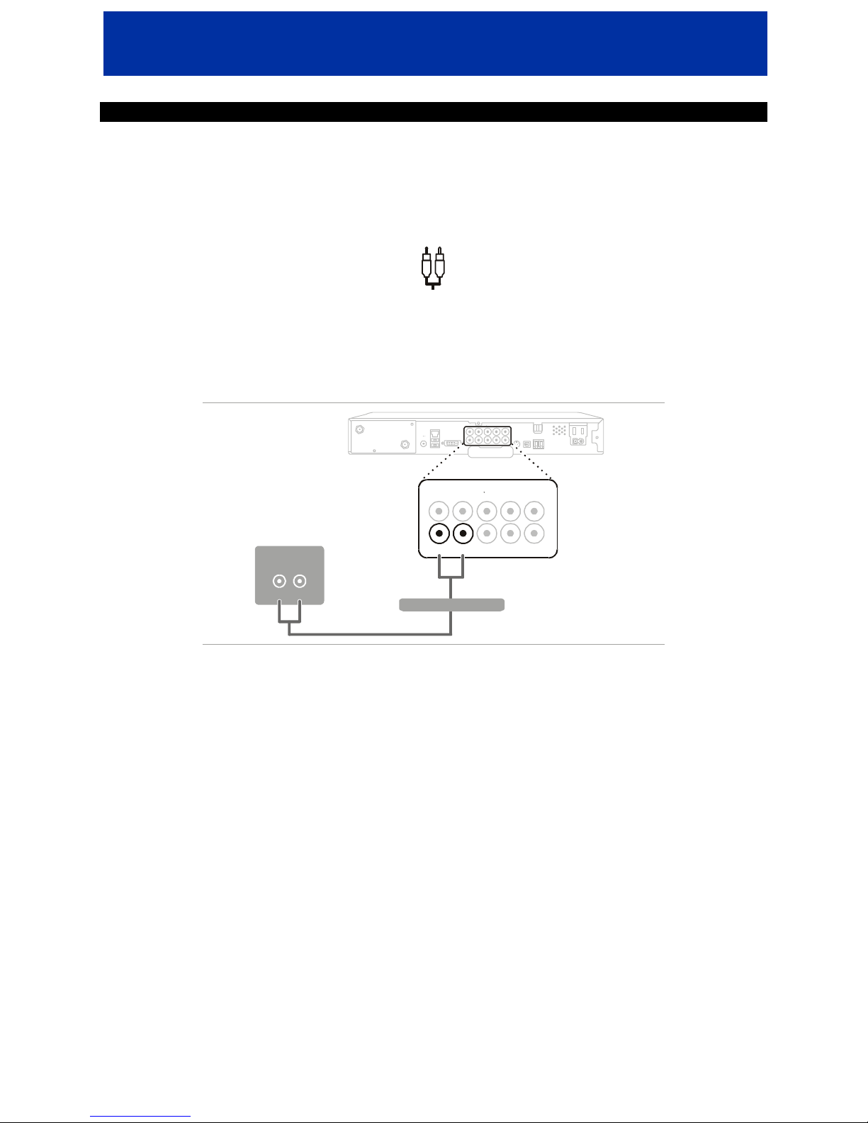
To connect your audio connections for HDTV:
• Connect the stereo audio cable to the AUDIO OUT R and Lconnectors on the DCT6200 and the AUDIO
INPUT RIGHT and LEFT connectors on the HDTV:
AUDIO IN
VIDEO
R
IN
L
OUT
SPDIF
YPb
Pr
AUDIO
INPUT
LR
HDTV
A
UDIO OUT
Stereo Audio Cable
After you have finished connecting your DCT6200, see “Setting Up Your New DCT6200 for Digital Cable
Services” on page 22.

12
Audio Connections for an A/V Receiver
There are three options available for audio connections to your A/V receiver:
• Optical (OPTICAL SPDIF)
• Coaxial (SPDIF)
• Stereo audio (AUDIO Rand L)
If your equipment supports it, the optical (OPTICAL SPDIF) or coaxial (SPDIF) audio outputs may be used in
place of the stereo audio outputs (AUDIO R and L). In most cases these outputs offer a higher level of
audio quality, including support for 5.1 surround sound.
To connect your audio connections for an A/V receiver, choose one of the following:
• Optical SPDIF: Connect the optical SPDIF cable to the OPTICAL SPDIF connector on the DCT6200
and the OPTICAL connector on the A/V receiver.
• SPDIF: Connect the digital audio cable to the SPDIF connector on the DCT6200 and the DIGITAL
INPUT COAX connector on the A/V receiver.
• Stereo audio: Connect the stereo audio cable to the AUDIO OUT R and Lconnectors on the DCT6200
and the AUDIO RIGHT and AUDIO LEFT connectors on the A/V receiver.
CABLE/TV DIGITAL INPUT
COAX
OPTICAL
AUDIO
LR
A/V Receiver
AUDIO IN
A
UDIO OUT OPTICAL
SPDIF
VIDEO
R
IN
L
OUT
SPDIF
PbPr
S-VIDEO
Choose one
Optical SPDIF cable
Digital Audio Cable
Stereo Audio Cable
After you have finished connecting your DCT6200, see “Setting Up Your New DCT6200 for Digital Cable
Services” on page 22.
a`qSOMM rëÉê dìáÇÉ
13
CONNECTING YOUR DCT6200 TO AN HDTV AND D-VHS
To record high definition programming, you must have a D-VHS digital VCR and connect to the
IEEE 1394 connector on your DCT6200.
For the connections described below you will need the following cables:
RF (75 ohm)
(supplied)
IEEE 1394
(2)
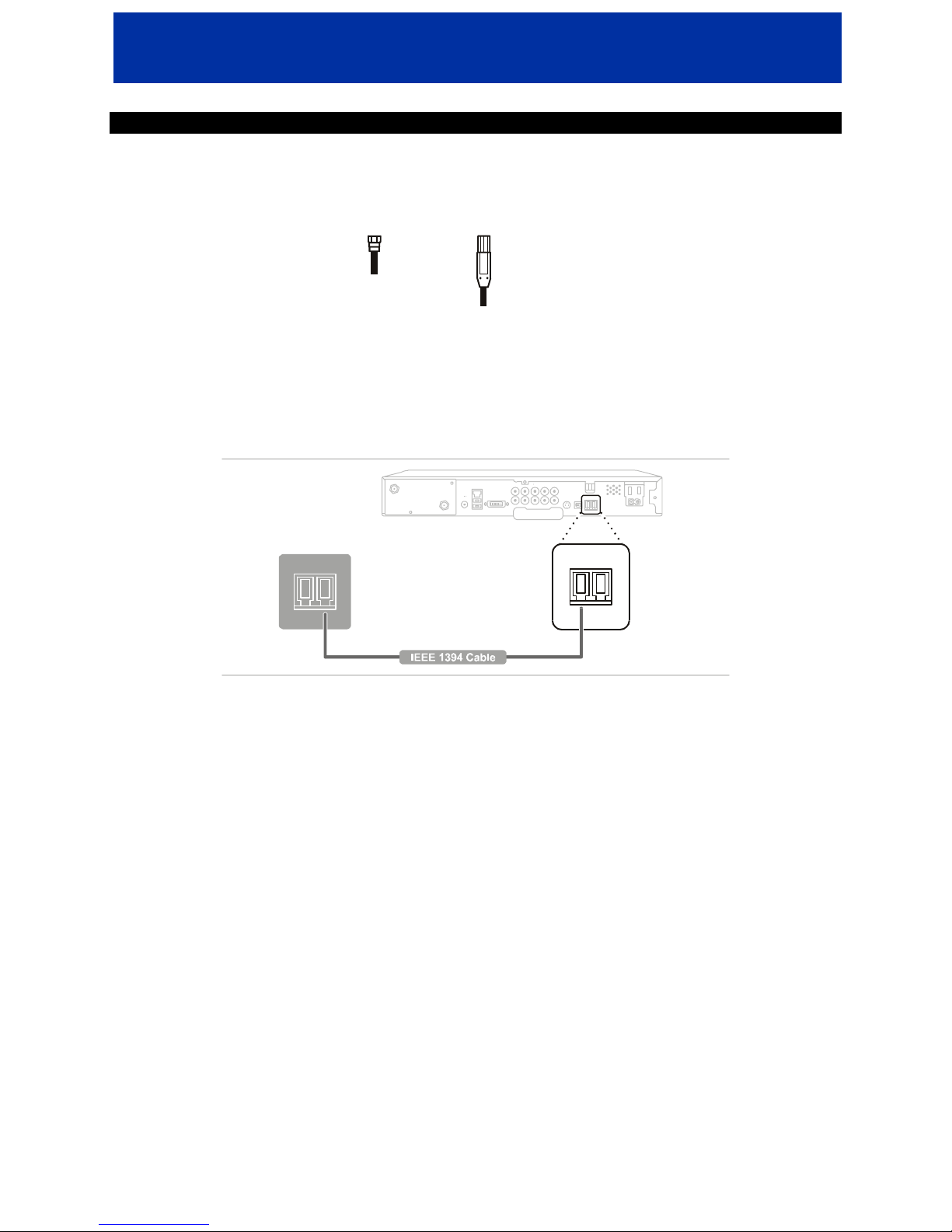
To connect your DCT6200 to an HDTV and D-VHS digital VCR:
1 Connect an RF coaxial cable to the cable wall outlet and the CABLE IN connector on the DCT6200.
2 Connect an IEEE 1394 cable to the IEEE 1394 connectors on your DCT6200 and D-VHS digital VCR.
IEEE-1394
IEEE 1394
D-VHS
3 Connect an IEEE 1394 cable to the IEEE 1394 connectors on your D-VHS digital VCR and HDTV.
The IEEE 1394 is a video and audio connection so no audio connections are required if you are using the
IEEE 1394 connection.
On-screen graphics will not be displayed when you are using the IEEE 1394 connection on the rear panel
of the DCT6200.
After you have finished connecting your DCT6200, see “Setting Up Your New DCT6200 for Digital Cable
Services” on page 22.
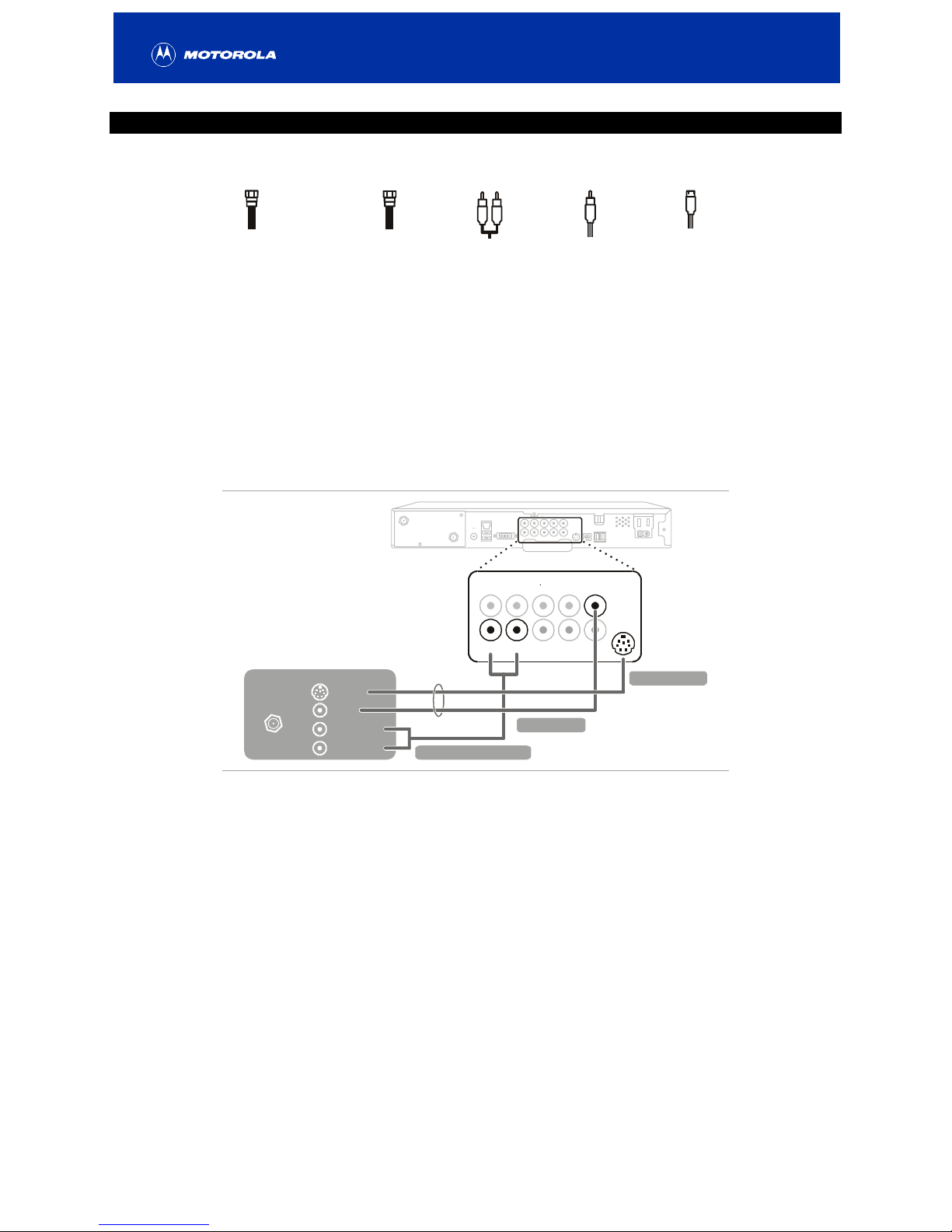
14
CONNECTING YOUR DCT6200 TO A STANDARD DEFINITION STEREO TV
For the connections described below you will need the following cables:
RF (75 ohm)
(2: one supplied;
one extra)
or
RF (75 ohm)
(supplied)
A
udio
(supplied)
V
ideo
S-Video
1 Connect an RF coaxial cable to the cable wall outlet and the CABLE IN connector on the DCT6200.
2 Connect a second RF coaxial cable to the TO TV/VCR connector on the DCT6200 and the
CABLE/ANTENNA IN connector on the TV.
Or
Connect the stereo audio cable to the AUDIO OUT R and Lconnectors on the DCT6200 and the
INPUT AUDIO RIGHT and LEFT connectors on the stereo TV. Connect a video cable to the VIDEO OUT
connector on the DCT6200 and the INPUT VIDEO on the TV or an S-video cable to the S-VIDEO
connectors on the DCT6200 and the TV.
Stereo TV
Either / or
S-VIDEO
CABLE/
ANTENNA IN
VIDEO
AUDIO LEFT
AUDIO RIGHT
INPUT
AUDIO IN
A
UDIO OUT
VIDEO
R
IN
L
OUT
SPDIF
YPb
V
ideo Cable
S-Video Cable
Stereo Audio Cable
This video connection method doesn’t support High Definition video. For more information, see
“Connecting your DCT6200 to an HDTV” on page 9.
After you have finished connecting your DCT6200, see “Setting Up Your New DCT6200 for Digital Cable
Services” on page 22.
Table of contents


