Seating Matters Sorrento 2 User manual

Sorrento 2
TM
Instruction Manual

This Instruction Manual is frequently updated to ensure safe use of your chair.
Visit seatingmatters.com where you can nd a free copy of the most up to date version.
Terminologies
Patient
The person sitting in the chair.
User
Competent person with responsibility for the persons sitting in the chair as well as the
suitability of the equipment for the Patient. The User is responsible for checking the chair
for faults during the course of its use.
All instructions must be read and understood before the chair may be used.

1
Contents
2Technical Specication
4Operating Instructions
4Tilt in Space (Manual Option)
5Back Angle Adjustment (Manual Option)
6Leg Elevation (Manual Option)
7Back Height Adjustment
8Seat Depth Adjustment
9Seat Width Adjustment
10 Arm Removal
11 Arm Height Adjustment
12 Footplate Angle
13 Footplate Height
14 Seat Cushion
15 Chair Function (Motorised Option)
18 Chair Movement
20 Cleaning Instructions
21 Safety Instructions
22 Maintenance & Servicing
23 Recycling Policy
24 Warranty
25 Intellectual Property

2
Sorrento 2TM
Technical
Specication

3
Basic Dimensions
A Overall Height*
BBack Height
C Seat Height*
D Overall Length
Standard: 50" / 1270mm
Range: 48"-54" / 1220mm-1370mm
Standard: 28" / 710mm
Range: 26"-32" / 660mm-810mm
24" / 600mm
49" / 1250mm
*Height measurements are based on 100mm castors.
Footplate Height Adjustments (from seat)
EHigh
FLow
15" / 380mm
20" / 510mm
Available Seat and Overall Widths
G (Seat Width)
14" / 350mm*
16" / 400mm
18" / 450mm
20" / 500mm
22" / 550mm
24" / 600mm
H (Overall Width)
25" / 660mm
25" / 660mm
26" / 670mm
28" / 720mm
30" / 770mm
32" / 820mm
* This seat width is achieved using a 400mm/16" seat
width and a set of 25mm/1" padded arm covers.
Arm Height Options (from seat cushion)
ILow
JMedium
KHigh
6" / 160mm
7" / 185mm
8" / 210mm
Seat Depth
L17 - 22" / 430mm - 550mm
Clearance Height
M 5" / 130mm*
*Height measurements are based on 100mm castors.
Full Recline Length
N 69" / 1750mm
Recline and Tilt Angles
ii Back Angle Recline
90° - 130°
40° range
iii Leg Rest Angle
80° - 150°
70° range
iv Tilt in Space
From 5° forward, or anterior, tilt to 30° or 45°
backward tilt (dependent on chair model)
Chair Weight Unloaded
Motorised: 10 Stone / 64 Kg / 141 lb
Manual: 8 Stone / 51 Kg / 111 lb
Patient Weight Limit
31.5 Stone / 200 Kg / 440 lb
A
B
C
E
F
G
H
ii
iii iv
IJ
L
K
N
M
D
4
For motorised option, see page 15.
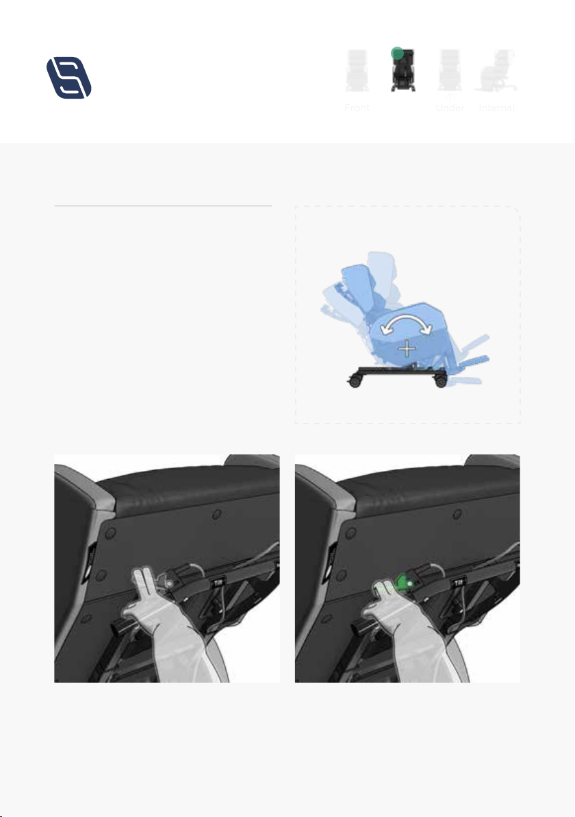
To adjust the tilt angle of the chair (g.1).
From the back of the chair, place both
hands on the push handle and locate the
left release lever (g.1a) with your
left hand. To tilt the chair, close your left
hand pulling the lever towards you (g.1b).
With the lever engaged, tilt the chair to the
required angle and release the lever again
to lock the tilt in this position.
Operating
Instructions
Back
Under
Internal
Front
Tilt in Space (Manual Option)
(g.1)
(g.1a) (g.1b)
5
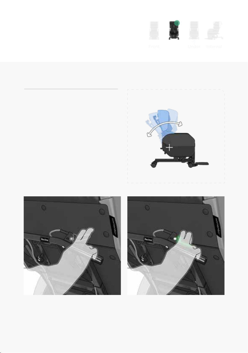
For motorised option, see page 15.
To adjust the back recline of the
chair (g.2).
From the back of the chair, place both
hands on the push handle and locate the
right release lever with your right
hand (g.2a). To recline the back of the
chair, close your right hand pulling the
lever towards you (g.2b). With the lever
engaged, recline the back to the required
angle and release the lever again to lock
the back in this position.
Back Angle Adjustment (Manual Option)
(g.2)
(g.2a) (g.2b)
Back
Under
Internal
Front

6
For motorised option, see page 15.
To adjust the angle of legrest
elevation (g.3).
From the front of the chair, locate the
leg rest lever attached to the right side
base frame. (g.3a). To elevate the leg
rest, engage the release lever, pushing it
downwards. (g.3b). If adjusting the legrest
elevation while the patient is in the chair,
assist the elevation. To retract the leg rest,
engage the release lever and pushing the
leg rest assembly inwards.
Leg Elevation (Manual Option)
(g.3)
(g.3a) (g.3b)
Back
Under
Internal
Front

7
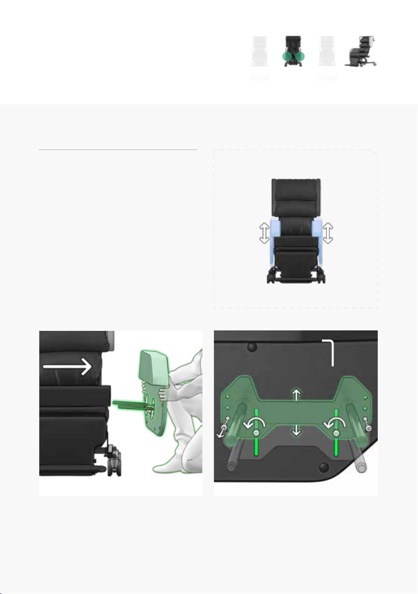
To adjust the back height of the
chair (g.4).
Remove left safety knob fully and loosen
right adjustment knob so the back can slide
freely (g.4a). Loosen the sliding bolts if
necessary. Slide the back up or down to the
desired back height position, tighten the
right adjustment knob then reattach and
tighten the left safety knob (g.4b).
Back Height Adjustment
(g.4)
(g.4a) (g.4b)
Back
Under
Internal
Front

8
Back
Under
Internal
Front
To adjust the seat depth of the chair (g.5).
From the back of the chair, disengage the
seat depth clamping lever by pushing it
downwards (g.5a).With your right hand
disengage the seat depth safety plunger
and push the seat base assembly forward
or back to the required position (g.5b).
Ensure the safety pin locates to the desired
position before re-engaging the seat depth
clamping lever. The seat depth settings can
be found below.
Seat Depth Adjustment
(g.5)
(g.5a) (g.5b)
*There are six options for seat depth.
0430mm 1450mm 2475mm 3500mm 4525mm 5550mm
17" 18" 19" 20" 21" 22"
9
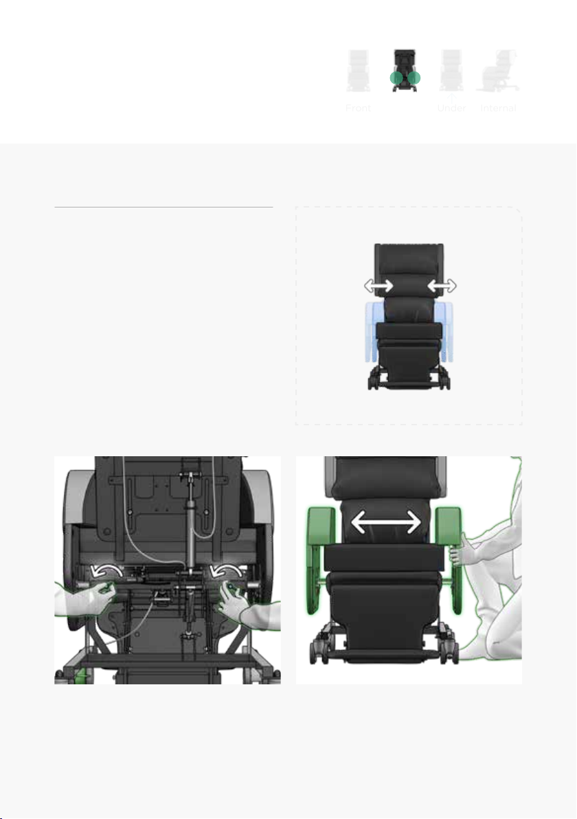
Seat Width Adjustment
To increase or decrease the seat width of
the chair (g.6).
From the back of the chair locate the
blue wing knobs on the left and right of
the seat frame, loosening them slightly.
(g.6a) Reposition the arms to the required
position (g.6b) and tighten both wing
knobs to resecure.
(g.6)
(g.6a) (g.6b)
Back
Under
Internal
Front
10
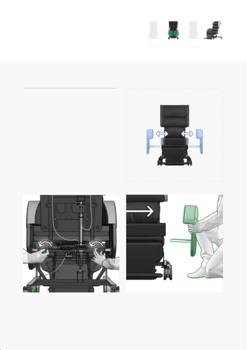
Arm Removal
To remove the arms of the chair (g.7).
From the back of the chair locate the blue
wing knob on the side of the arm you want
to remove (g.7a). Loosen the wing knob
slightly. With the arm now free, remove it
and set it in a safe place. Tighten the wing
knob to resecure the arm.
(g.7)
(g.7a) (g.7b)
Back
Under
Internal
Front
11
Arm Height Adjustment
To adjust the arm height of the
chair (g.8).
With the arm removed (g.8a), using a
5mm allen key remove the safety bolts from
the arm bracket. Loosen the sliding bolts
if necessary. Slide the arm bracket to the
desired position (g.8b).Secure the safety
bolts in place and tighten the sliding bolts.
Tighten the wing knob to resecure the arm.
(g.8)
(g.8b)(g.8a)
5mm
Back
Under
Internal
Front

12
Footplate Height
To adjust the seat to footplate height of
the chair (g.9).
From the front of the chair, and with both
hands, locate the two spring plungers at
either side of the calf pad (g.9a).
Pull both spring plungers outward at the
same time and move the footplate to the
required position before releasing.
The pin of the spring plunger will locate
to the nearest hole position and lock
into place (g.9b).
(g.9)
(g.9a) (g.9b)
Back
Under
Internal
Front

13
Footplate Angle
To adjust the angle of the footplate (g.10).
Some tools are required to carry out this
adjustment (g.10a).
Using a 4mm allen key and 10mm spanner,
loosen and remove the xing bolt at either
side of the footplate pivot (g.10a).
Relocate both bolts to the required setting
(g.10b) and tighten securely.
(g.10)
(g.10a) (g.10b)
Back
Under
Internal
Front
4mm 10mm

14
Seat Cushion
Removal and tting of the modular
Seating Matters cushion (g.11).
The underside of the Seating Matters
cushion and the baseboard of the chair are
upholstered with non-slip material, which
combine to create a friction contact when
the chair is occupied. To t the cushion
correctly, place the cushion onto the
baseboard of the chair, with the non-slip
underside of the cushion facing downwards
(g.11a). The rear, zipped end of the
cushion should be facing towards the back
of the chair (g.11b). See cushion label for
orientation. To remove the cushion, simply
lift it out from the chair.
Correct tment of the Seating Matters cushion is important as the structure of the foam
allows good immersion ONLY when tted as instructed above.
(g.11)
(g.11a) (g.11b)
Back
Under
Internal
Front
1515
Chair Function (Motorised Option)
Forward
Tilt Backward
Tilt
Legrest
Down Legrest
Up
30°
Tilt Limit
45°
Tilt Limit
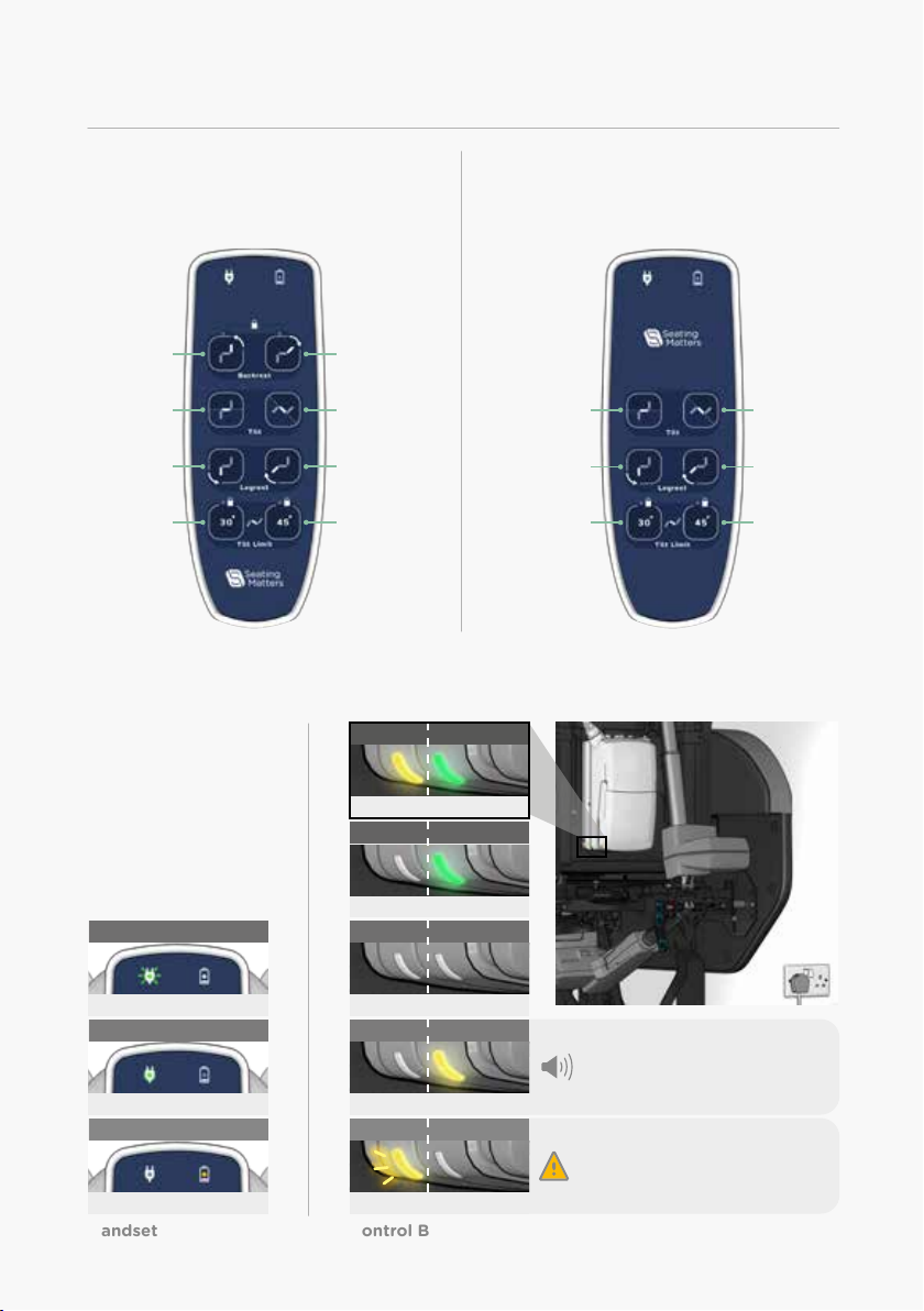
Part Motorised Handset
If your chair is a part motorised model,
Tilt in Space and Leg Elevation are
controlled by the handset.
Forward
Tilt Backward
Tilt
Legrest
Down Legrest
Up
30°
Tilt Limit
45°
Tilt Limit
Backrest
Up Backrest
Down
Fully Motorised Handset
If your chair is a fully motorised model,
Back Recline, Tilt in Space and Leg
Elevation are controlled by the handset.
Charging Status
Handset (g.12a) Control Box (g.12b)
Monitor the charging
status of your chair using
the Power lights on the
Handset (g.12a).
Status lights are also
located on the left side
of the control box and
battery (g.12b).
Control Box
Plugged in / Charging
Battery
Plugged in / Charging
Battery
Low Battery
Control Box
Plugged in / Fully charged
When error light shows switch o
and unplug your chair immediately.
Contact: technical@seatingmatters.com
The buzzer will make a warning
when a button on the hand control is
pressed and the battery is low.
Battery
Normal state / Not in operation
Control Box
Control Box
Control Box
Not in operation / Normal state
In operation / Using battery power
Orange Flashing Light - Error
Battery
Plugged in / Charging
Battery
Low Battery
Battery
Normal state / Not in operation
Orange Flashing Light
Green Light
Green Flashing Light
Plugged in / Charging
Plugged in / Fully charged
Low Battery
Battery
Battery
Battery
Battery
Battery
16
Chair Function (Motorised Option)
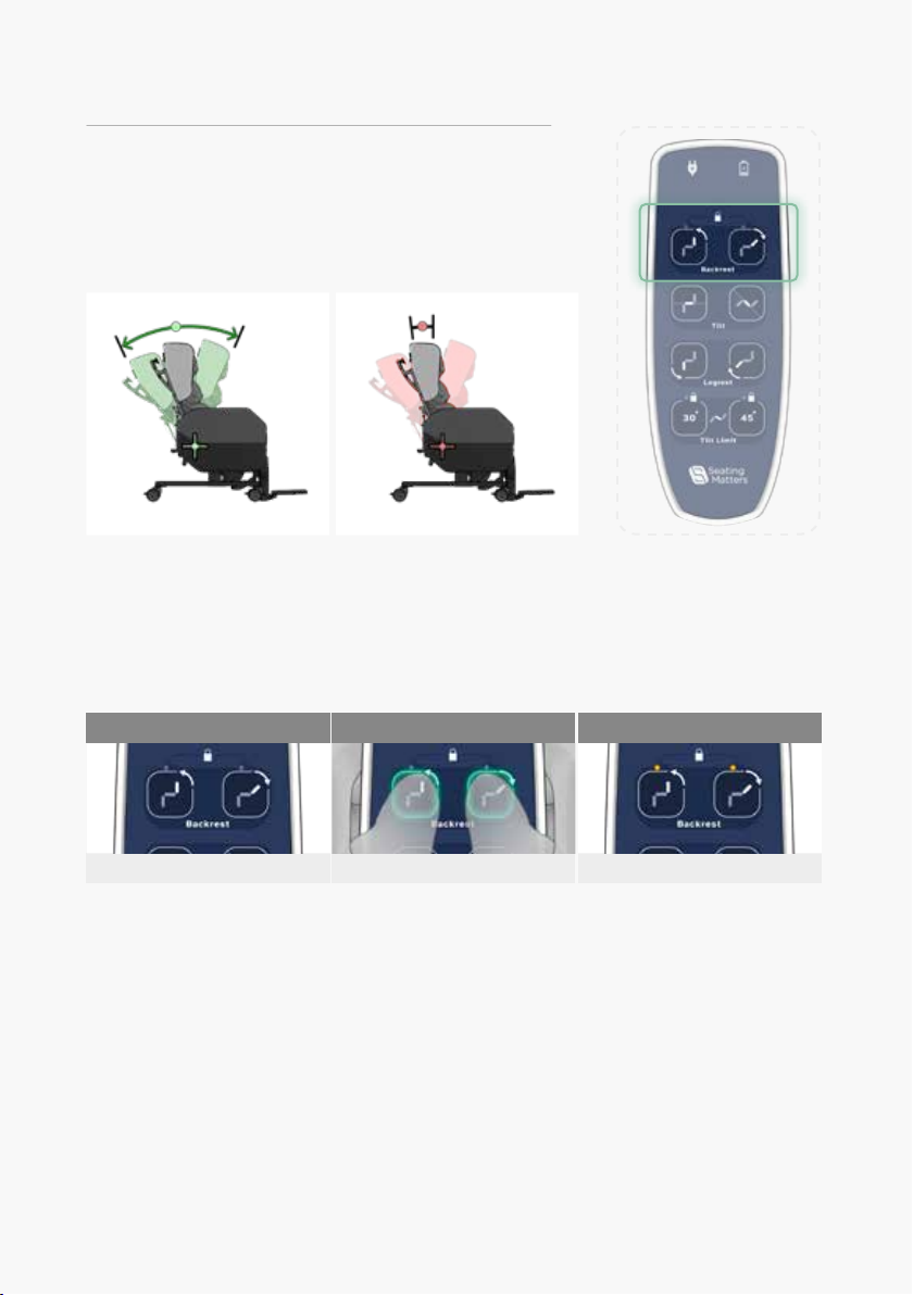
Backrest Lock (Fully Motorised Only)
If your chair is a fully motorised model,
the Backrest can be locked in position using
the handset.
Backrest Unlocked Backrest Locked
Lock/Unlock the Backrest
If the Backrest is unlocked, no lights will show above the Backrest buttons (g.13a).
Orange lights will indicate the Backrest is locked in position (g.13c).
To lock/unlock the Backrest press and hold both Backrest buttons for 5 seconds (g.13b).
Press and hold (5 Sec)
(g.13c)(g.13b)(g.13a) No lights.

17
(g.14b) (g.14c)
TIlt Limit set to 45°
Press and hold (5 Sec)
Chair Function (Motorised Option)
Tilt Limit
The Maxiumum Tilt Limit can be set using
the handset.
Set the Maxiumum Tilt Limit to 30° or 45°
To set the Tilt Limit press and hold the 30° or 45° button on the handset for 5 seconds (g.14b).
The orange light will indicate which setting is currently activated (fig.14a & fig.14c).
(g.14a)
TIlt Limit set to 30°
18
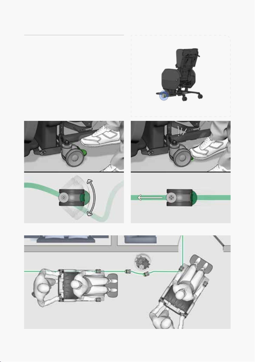
Chair Movement
Directional Lock Castor
For control of direction and
manoeuvrability while pushing the chair
(g.13c).
The directional lock castor is located on the
front left side of the chair (g.13).
To engage the directional lock castor
simply press the green pedal with your foot
(g.13a) and swivel the castor until it clicks
into the forward line (g.13b).(g.13)
(g.13a) Directional lock disengaged. (g.13b) Directional lock engaged.
(g.13c) Image showing use of the directional lock to improve manoeuvrability.
This manual suits for next models
1
Table of contents


