SEC America 7058 User manual

Model 7058 DC-DC Converter
Owner's Manual
SEC America Corp
SEC
Rev 4
June 3, 2018

TABLE OF CONTENTS
page
I Introduction 1
II Installation 1
2.1 Mounting 1
2.2 Connections 1
2.3 Methods of Converter Activation 2
III Performance Characteristics and Indicator Lights 3
IV Internal Adjustment of Output Voltage 5
4.1 Voltage Adjustment 5
V Warranty 6,7
VI Mechanical Drawing 8
VII Electrical Specifications 9

IIntroduction
Model7058isshippedinfullyassembledform.Theinstallershouldlocateabagcontainingaquantity
of(4)bladeterminalsintendedforusewiththeI/Ocablingtobeusedwiththeunit.Afterremovalof
theunitfromitspackagingitshouldbeverifiedthatithassufferednodamageinshipment.Itisvery
importanttofollowtheinstructionsofthismanualtoensureproperconnectionandmounting.
Model7058isahighpower12Volttoamaximumof58.4VoltDC‐DCbatterychargercapableof
delivering20Atoalithiumironphosphatebatterybankof16cellsandnominal51.2Vrating.Itis
designedformountinginvehiclesofalltypesandiscapableofenduringharshvibrationandshock.
IIInstallation
2.1Mounting
Model7058hasanoveralllengthof17.85incheswithmountingflangesincludedinthisdimension.
Holemountingcentersare17.34x3.93(inches)
2.2Connections
ToolsRequired‐1flatbladescrewdriver(1/4in.wide)
Figure1showstheconnectionpanelviewofthe7058.
4040
Input
24 VDC
Common
Ground
Output
nominal
Hi Charge TBA, 1 - enable / ignition
TBA, 2 - 24 VDC aux. TBA
Circuit breakers
TBB
123
12
1
2
Float Charge
Figure1
Page1

PriortoMainInputPowerConnections:
The7058comessuppliedwith4bladeterminalsintendedforcrimpingonto#2AWGmulti‐stranded
batterycable.Itisimportanttoutilizetheseterminalsinordertorealizereliablehighcurrentcapacity
connectionsbetweentheterminalblockandinput/outputcables.
Priortohookuptothevehiclepowersource,thebuttonsonthetwocircuitbreakersshownin
Figure1shouldbepulledoutintotheOFFposition.Thispositionisindicatedbytheexposureofthe
whiteportionofthebreakerbuttonshaft.Thisensuresthatthereisnosparkingfromthesourceof
powerandalsoallowsareprieveincasethereshouldbeahookuperror.(Thiserrorwouldhavetobe
detectedpriortoenergizingtheunit).
Oncethebreakerbuttonsarepulled,proceedtomakeconnectionsasfollows:
A) Connectinput+24Vlinetoposition#1ofTBB.
B) ConnectinputGROUNDtoposition#2ofTBB.
C) Connectoutput(+51Vnominal)linetoposition#3ofTBB.
D) ConnectoutputGROUNDtoposition#2.
Priortodepressingthecircuitbreakerbuttons,installershould:
1) EnsurethathookupinstepsAthroughDarecorrect.
2) Selectthemethodofconverteractivation.
GroundingStud:Theflatsideoftheunitisequippedwithagroundstudwhichisconnectedtothe
7058housing.Itmaybeconnectedtothebatterygroundofthevehicleattheuser’soption.
2.3MethodsofConverterActivation(withallcircuitbreakerson)
A) Connectterminal#1toterminal#2onterminalblockTBA.(The7058isshippedfrom
thefactorywithashortingjumperinplacebetweenthoseterminals.)Thisconfiguration
allowsforconverteractivationbyturningthesourcepower“ON”.Forthismethodthe
circuitbreakersmustbeleftintheONposition.
B) Alternatelytheconvertercanbeswitchedonfromthevehicle’signitionsystem.
Removethejumperbetweenterminals#1and#2onTBA.Toenergizethecharger,
connectterminal1to24Vthroughtheignitionswitchoranotherswitchthatwould
enableterminal 1toaccess12VDC.Forthismethodthecircuitbreakersmustbeleftin
ONposition.
C) Terminal#1canbeconnectedtoterminal#2througharemoteON/OFFswitchorrelay
contactstherebyactivatingthecharger.Forthismethodthecircuitbreakersmustbe
leftinONposition.
Page2

IIIPerformanceCharacteristicsandIndicatorLightFunctions
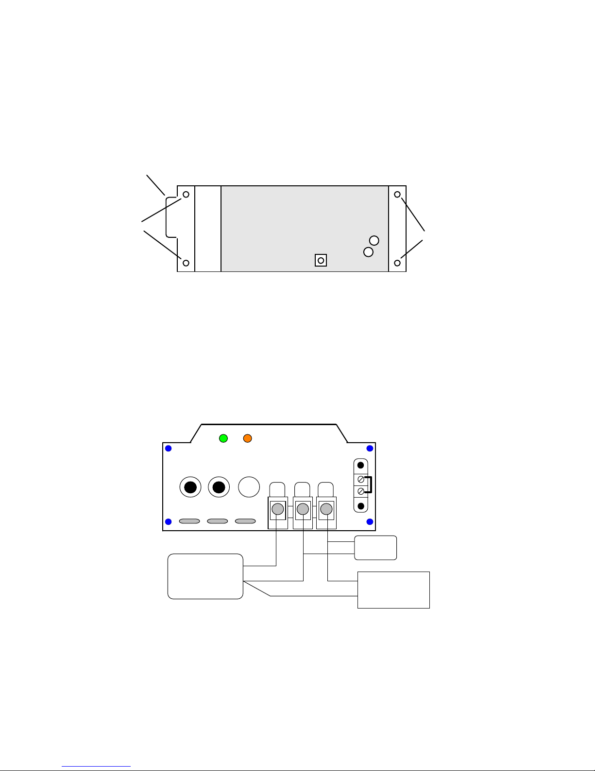
Once7058isproperlyconnected,itisreadyforactivation.Amicroprocessorcontrolsthe7058
performanceandprotectionfunctions:
ONSTATEFUNCTIONS
OutputVoltageCycles
A) Uponinitialturnon,theunitcomesonwithachargingvoltageof58.4VDClimitedto30A.This
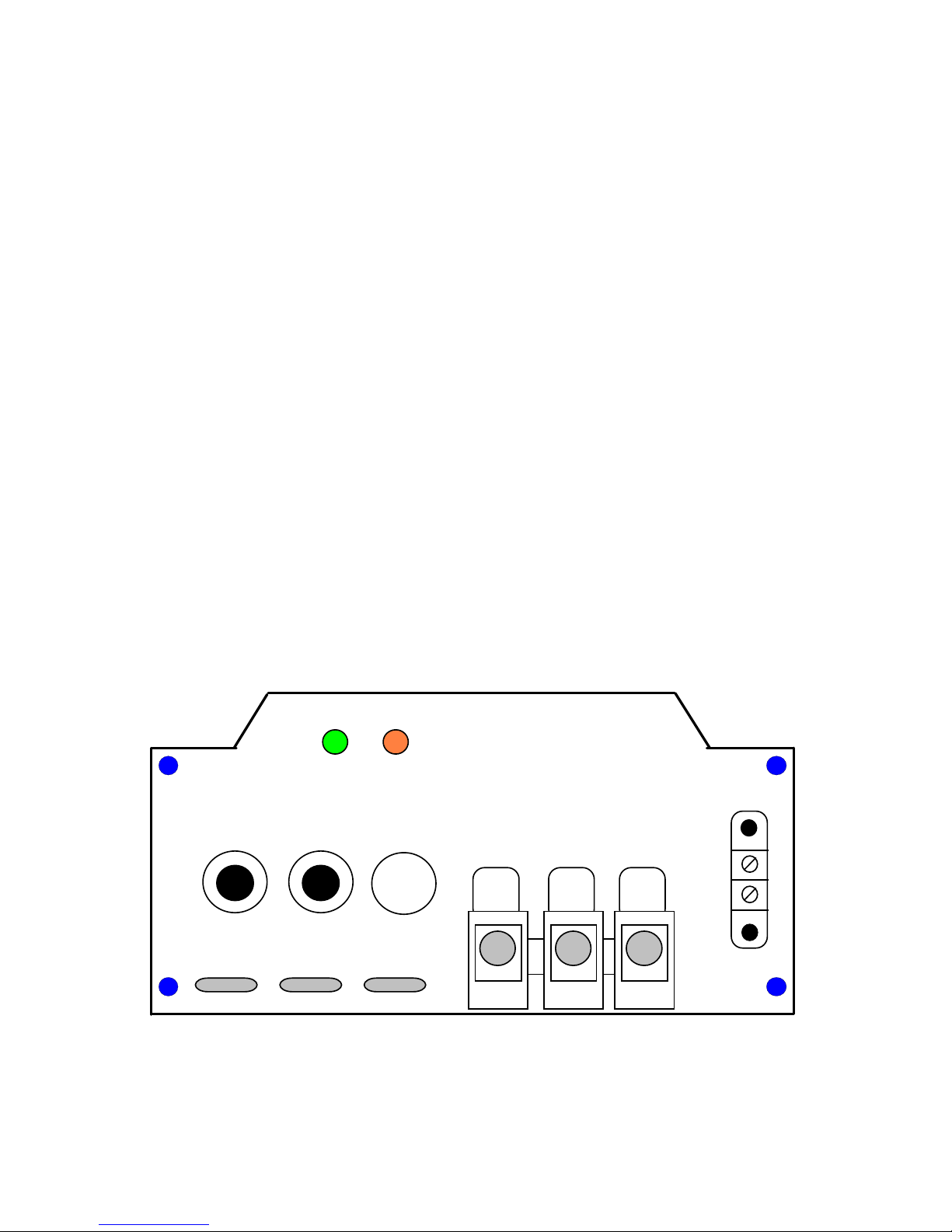
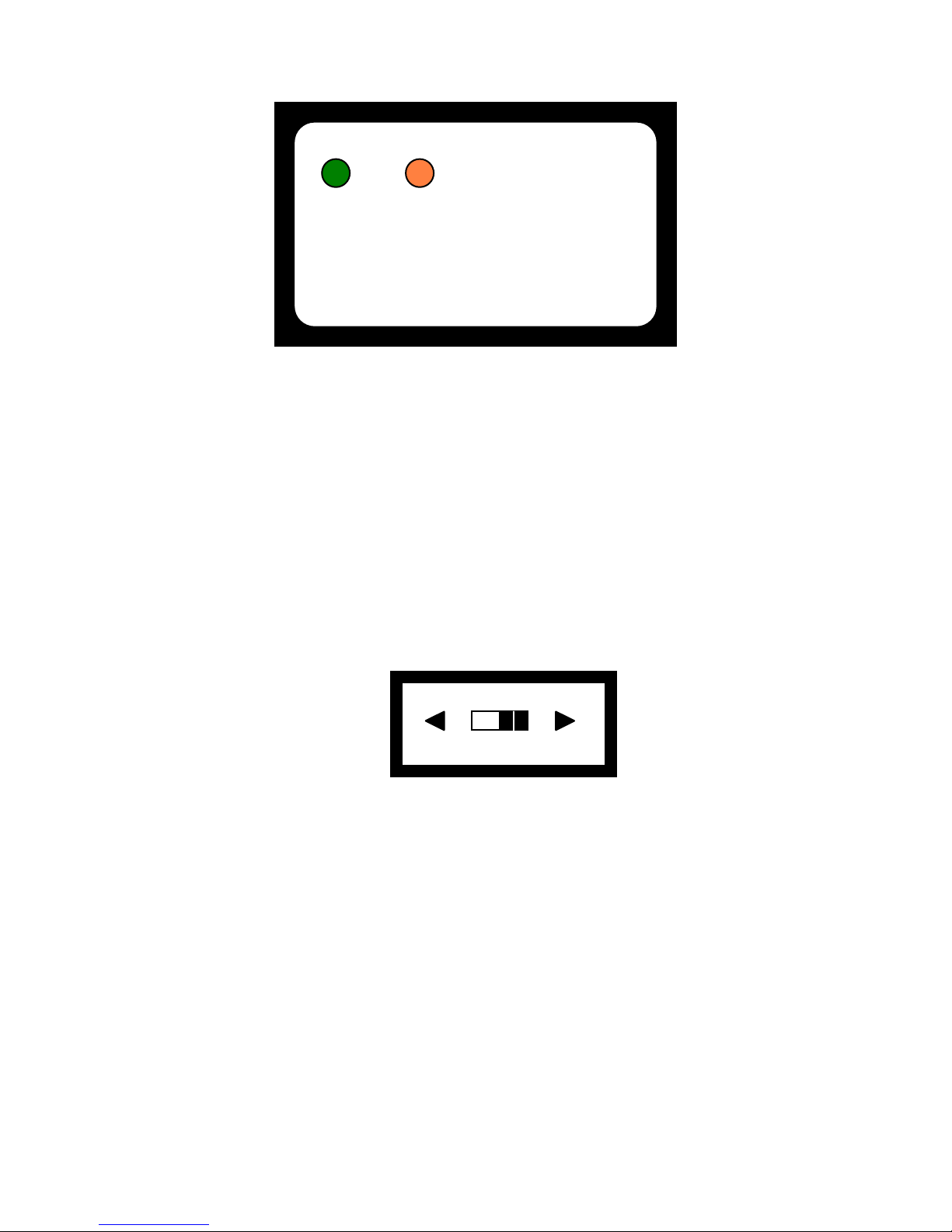
stateisdiscerniblebytheilluminationofthegreenlight(highchargeindicator).Ifthebattery
bank(load)becomesfullychargedwithbatterychargingcurrentbeinglessthan1.5A,theunit
willstopchargingandremaininastateofsensingtheoutputvoltage.Inthisstatetheamber
lightturnsONandthegreenoneturnsOFF.
B) Shouldthevoltagefloatdownto51V,the7058willautoadjustitsvoltageto58.4VDCwhichis
discerniblebytheamberlightturningoffandthegreenlight(highchargeindicator)turningon.
C) Asthebatterybankchargesupagain,the7058monitorsoutputcurrent.Whenthecurrentdips
below1A‐2A,thechargerturnsoff.ThisbecomesdiscerniblebythegreenlightturningOFFas
theamberlightturnsON.
D) Eachtimethechargerisactivatedbytheremoteterminalsorenergizedbytheapplicationof
power,itgoesintochargemode.
CurrentLimitandOverload
A) Inchargemode,the7058willsupplyuptoamaximumof30Aat58.4VDCandwillcurrentlimit
shouldtheloaddemandmorethan32A.
B) Shouldsevereloadingoccur,bringingtheoutputvoltagebelow36VDC,theunitwillshutoff.
C) Oncetheunithasenduredsuchsevereoverloads(B),inorderforittoresumenormalfunctions
theoverloadmustberemoved.Thenthechargerneedstoberesetbypowerdownandthen
powerupbyanyofthemeansdescribedinsection2.3.Tenminutesshouldbeallowedpriorto
powerup.Inthisperiodthecoolingfanoftheunitmaybringinternaltemperaturesdownto
tolerablelimits.
InputVoltageLimits
A) ThenominalinputoperatingvoltageoftheModel7058is24VDC.Theunitwillacceptarange
between21.5VDCand32VDC.Wheninputvoltageisoutsideofthisrange,theunitshuts
downandtheamberlightflashescontinuously.
B) Aftertheunitshutsdownduetotheinputvoltagedippingbelow21.5,itwillturnbackONonce
inputvoltageisrestoredbacktoatleast23.5Vafteraminimumtimelapseof5seconds.This
hysteresisanddelaypreventON/OFFinputchatter.
OFFSTATE
A) Whentheunitisinactivebothlightsareoff.
Page3

Table1showsthecorrespondencebetweenindicatorlightstatesandthestateofunit’soperation:
GREEN AMBER
ONOFF
FLASHING
Charging Off
OFFON Charge On
OFF Low Input Voltage
OFF OFF Unit Off
STATE
Table1
IV Battery Type Selection
Model 7058 is preprogrammed at the factory to be usable with batteries of 2 distinctive chemistries – 16 cell
Lithium Iron Phosphate and 48V Lead Acid (AGM). The algorithm to charge Lithium Iron Phosphate or AGM is
selectable by the position of a slide switch located on the blank panel of the unit.
Units are shipped from the factory with switch position in the Lithium mode. Figure 2 shows a battery type
selector switch available at the rear of the unit to allow the user to select the AGM profile.
Battery Selector Switch
Lithium
AGM
Figure #2
Page4

IVInternalAdjustmentofOutputVoltage
Thereshouldbenoneedforanyadjustmentprovidedtheunitisusedforitsintendedapplication.Intheeventthatthereis
aneedtoaltertheoutputvoltage,usethefollowingprocedure:
VaryingtheadjustmentsoftheModel7058requiresthetechniciantohaveastableDCpowersupplyvariablefromatleast
20VDCto30VDCwithacurrentcapacityofatleast3A.Thisadjustmentshouldbeconductedwithnoloadonthecharger.
Toaccesstheadjustmentturntheunitupsidedownandremovethebaseplatebyunscrewingthe4securingscrewsinits
corners.
Orienttheconverterupsidedownandhorizontallywiththeconnectionpaneltotheleftasshowninfigure#3.
Potted Module
Vadj. Pot.
Output
I/O terminal block
securing screws
securing screws
Figure #3
Apotentiometercanbenoticed.Pinksealantcompoundmayneedtoberemovedtogainaccess.
Thepotentiometerisusedtoadjustoutputvoltageinarangeof47.5‐56.3VDCatnoloadfloatcondition(amberlightis
ON).7058isfactoryadjustedintheLithiumIronPhosphatesettingto51.2VDCoutputatnoload(floatvoltage).This
correspondstoahighchargevoltageof58.4.Ifthefloatvoltageischanged,thehighchargevoltagewillautomaticallyalso
bealteredbythesameamount.
4.1)InstrumentationConfigurationforVoltageAdjustment
a)HookuptheunitundertestasshowninFigure#4
4040
Input
24 VDC
Common
Ground
Output
Nominal
Green
Light
Circuit breakers
TBB
123
12
TBA, 1 - enable / ignition
TBA, 2 - 24 VDC aux. TBA
1
2
Power Supply
+24V
Ret
DVM
+50V-60V
Ret
Figure #4
Amber
Light
4A @ 50V
Load.
+
-
b)Makesureterminals1&2onTBAarejumpered(shortedtogether)andthatthepowersupplyisturnedoff.SettheDVM
totheappropriatescaletoread60VDCatthedesiredaccuracy.
c)Energizepowersupplyandadjustitsoutputvoltageto+24VDC.Adjustpotentiometertothedesiredoutput(between
47.5VDCand56VDC)asreadontheDVM.
d)Turnoffpowersupply.
Page5

VWarrantyandRepair
ShouldyourinvestigationsindicatethatyournewModel7058isdefectiveordamagedandyourunitis
stillunderwarranty,contactSECAmericaCorp.at802‐865‐8388andobtainreturnmerchandise
authorizationforcreditorexchange.
Ifthewarrantyperiodhasexpiredorifthewarrantyhasbeenviolatedduetooperatorerrorormisuse,
call:
SECAmerica,Corp,RepairDepartment,at802‐865‐8388orfaxSECAmericaCorp.at802‐865‐8389to
receiveauthorizationforshipmentbacktofactoryforanalysisandpossiblerepair.
Warranty
TheModel7058hasa2yearwarrantycoveringpartsandlabor.Thewarrantyisfoundonpage7of
thisowner’smanual.
Page6

We warrant each instrument, sold by us, or our authorized agents, to be
free from defects in material and workmanship and that it will perform
within applicable specifications for a period of two years after original
shipment. Our obligation under this guarantee is limited to repairing or
replacing any instrument or any part thereof,except fuses and pilot lights,
which shall within one year after delivery to the original purchaser, be
returned to us with transportation charges prepaid, prove after our exa-
mination to be thus defective.
LIMITED WARRANTY
The above limited warranties take the place of all other warranties,
expressed or implied, and correction of such defects by replacement or
repair shall constitute a fulfillment of all obligations under the terms of the
warranties. The warranties do not cover any unit that has been damaged
either in transit or by misuse, accident or negligence. No warranty or re-
presentation by anyone other than this Company shall be binding on us.
To return a unit send only to the following address:
SEC America, Corp
78 Ethan Allen Drive
S. Burlington, VT 05403
PLEASE RETAIN YOUR ORIGINAL BILL OF SALE. IT MUST
BE SUBMITTED WHEN MAKING ANY WARRANTY CLAIM
Page 7

VI Mechanical Drawing
Page 8

VII Electrical Specifications:
Output Voltage: 58.4V Charge Nominal (16 cell LiFePO4)
Output Voltage Adjust Range 47.5 VDC to 56.0 VDC (float)
Continuous Max Load Amps: 30 ADC @ 40C ambient (Input 12.5 VDC)
22 ADC @ 60C ambient
Maximum Power Dissipation: 110 Watts @ Full Load (30A, 58.4 VDC out)
Maximum Input Current: 77 A (24 VDC in)
Overload Protection: Electronically current limited (primary protection)
Thermal Circuit Breakers at the Input (secondary
protection)
Cooling: Convection and Forced Air
Thermostat Controlled Fan
Output Ripple Voltage: 10 mV RMS (20C to 75C)
50 mV RMS (-30C)
Input Voltage Range: 21.5 VDC to 32 VDC
Input Output Isolation: Input and Output returns are Common (non isolated)
Low Voltage Cutout Circuit:
Low Voltage cutout point: 21.5 VDC
Low Voltage cutout Hysteresis: 1.8 VDC; Unit turns on at 23.5 VDC
Activation Circuits:
1) The unit may be activated through the command terminal #1 of terminal block TBA which
when connected to +24 VDC of the vehicle will turn the charger ON..
2) The charger may be turned on by energizing the primary power source.
Ambient Operating Temperature: -30C to + 60C
Maximum Humidity: 100% non condensing
Maximum Elevation: 15000 ft. above sea level
Mechanical Specifications:
Dimensions: See Drawing on Page 8
Shipping Weight: 16 lb.
Construction: Aluminum housing with painted steel end panels and base
Mounting Method: #12 Hardware via front and rear mounting flanges
Mounting Centers: 17.34 x 3.93 (inches)
Hook Up: 3 Position Splicer Terminal Blocks
Page 9

SEC America Corp
SEC
Table of contents
Other SEC America Media Converter manuals