SEC America 680 CE User manual

Model 680 CE, DC-DC Converter
Owner's Manual
SEC America Corp
SEC
April 1, 2019

TABLE OF CONTENTS
page
I Introduction 1
II Installation 1
2.1 Mounting 1
2.2 Connections 1
2.3 Methods of Converter Activation 2
III Internal Adjustments 3
3.1 Voltage Adjustment 3
3.2 Low Voltage Cutout 4
IV Warranty 5,6
V Mechanical Drawing of Base Plate 7
VI Electrical Specifications 8
I Introduction
Model 680CE is shipped in fully assembled form. The installer should locate a bag containing a quantity
of (4) blade terminals intended for use with the I/O cabling to be used with the unit. It is recommended
that #2 gauge multi stranded cable be used to minimize voltage drops through them. After removing the
unit from its packaging and ensuring that it has suffered no damage in shipment, it is important to read
this manual and follow its instructions to ensure proper connection and mounting.
Model 680CE is a high power 12 Volt to 24 Volt DC-DC converter capable of delivering 40A to its
load. It is designed for mounting in vehicles of all types and is capable of enduring harsh vibration and
shock conditions
II Installation
2.1 Mounting
Model 680CE has an overall length of 13.8 inches with mounting flanges included in this dimension.
Hole mounting centers are 13.3 x 3.93 (inches)
2.2 Connections
Tools Required - 1 flat blade screw driver (1/4 in. wide)
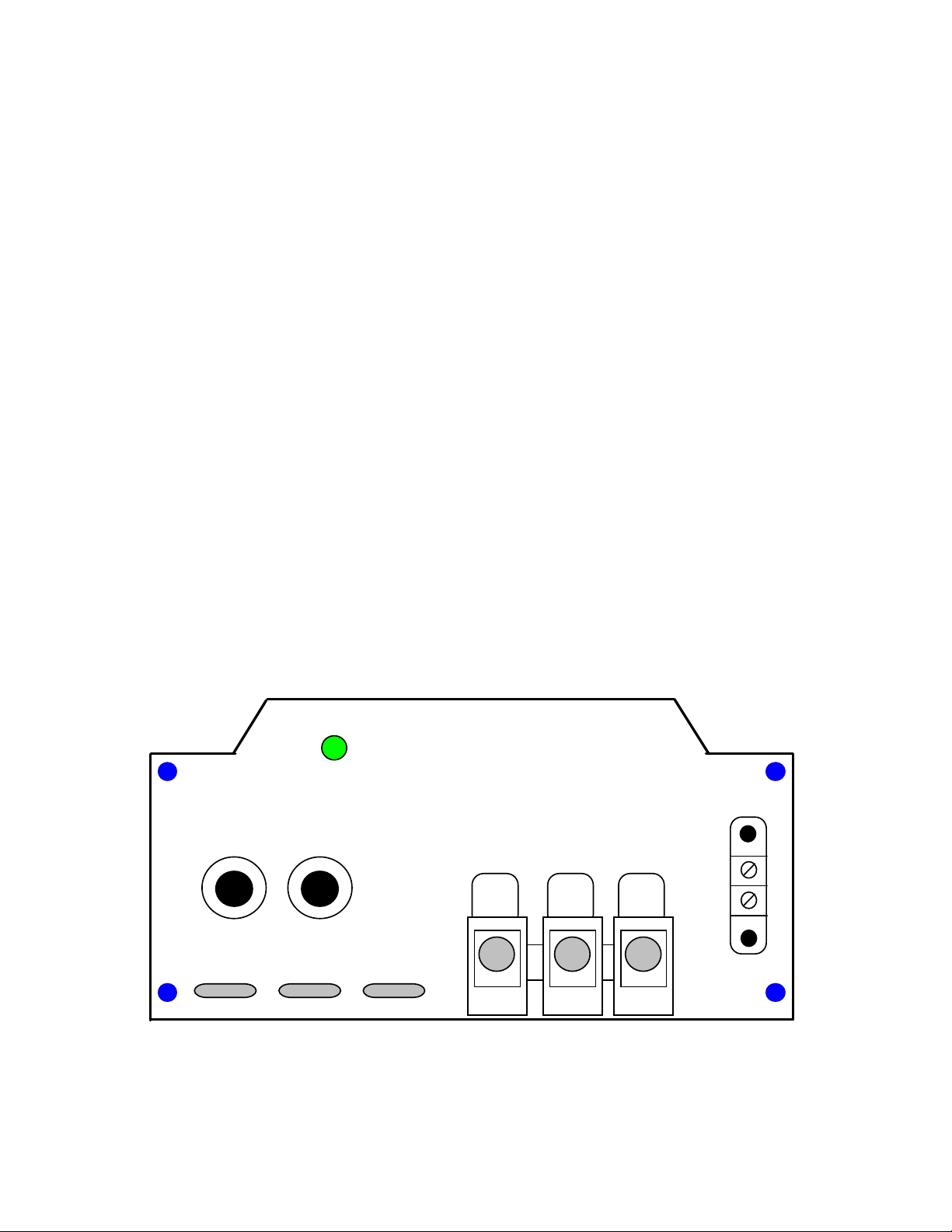
Figure 1 shows the connection panel view of the 680CE.
5050
Input
12 VDC
Common
Ground
Output
24 VDC
Activity
Light
TBA, 1 - enable / ignition
TBA, 2 - 12 VDC aux. TBA
The 680 CE, DC-DC Converter can be activated by:
1) Connecting Terminals 1 & 2 on TBA (as factory supplied)
2) By disconnecting Terminal 1 from Terminal 2 on TBA and
connecting terminal 1 to 12 VDC through an ignition switch
OR
Circuit breakers
TBB
123
12
1
2
Figure 1
Page 1

Prior to Main Input Power Connections:
Prior to hook up to the vehicular power source, the buttons on the two circuit breakers shown in
Figure 1 should be pulled out into the disconnect position. This position is indicated by the
exposure of the white portion of the breaker button shaft. This ensures that there is no sparking from
the source of power and also allows a reprieve in case there is a hook up error. (User should carefully
review connections as such an error would have to be detected prior to energizing the unit).
Once the breaker buttons are pulled, proceed to make connections as follows:
A) Connect input +12V line to position #1 of TBB.
B) Connect input 12V ground to position #2 of TBB.
C) Connect output +24 V line to position #3 of TBB.
D) Connect output 24 V ground to position #2 either at the Terminal block or other convenient
junction.
Prior to depressing the circuit breaker buttons, installer should:
1) Ensure that hook up in steps A through D is correct.
2) Select the suitable method of converter activation.
2.3 Methods of Converter Activation
A) Connect terminal #1 to terminal #2 on terminal block TBA. The 680CE is so configured
when shipped from the factory. This configuration allows for converter activation by
turning the source power ON and OFF.
B) The converter can be switched from the vehicle’s ignition system. For this method,
remove the shorting jumper between terminals #1 and #2 on TBA and connect terminal 1
to the ignition switch or other switch that can enable terminal 1 to access 12 VDC.
C) Terminal #1 can be connected to terminal #2 through a remote ON/OFF switch and
thereby activating the converter.
Page 2

III Internal Adjustments
Varying the adjustments of the Model 680CE require the technician to have a stable DC power supply
variable from at least 10 VDC to 15 VDC.
To access adjustments turn the unit upside down and remove the base plate by unscrewing the 4
securing screws in its corners. (See drawing 63-1448, p 6).
Orient the converter upside down and horizontally with the connection panel to the left as shown in
figure #2.
Potted Module
Vadj.
Cutout Adj.
(A) (B)
Bottom View
Terminal
Main
Block
Two potentiometers (A) and (B) can be noticed.
Potentiometer (A) is used to adjust the converter’s low voltage cutout point. This point corresponds to
the minimum input voltage necessary to keep the converter “ON” (maintaining approximately 26V at
the output).
When the converter is in the “OFF” state, the output voltage approximately equals the input voltage.
Potentiometer (B) is used to adjust output voltage.
3.1) Voltage Adjustment
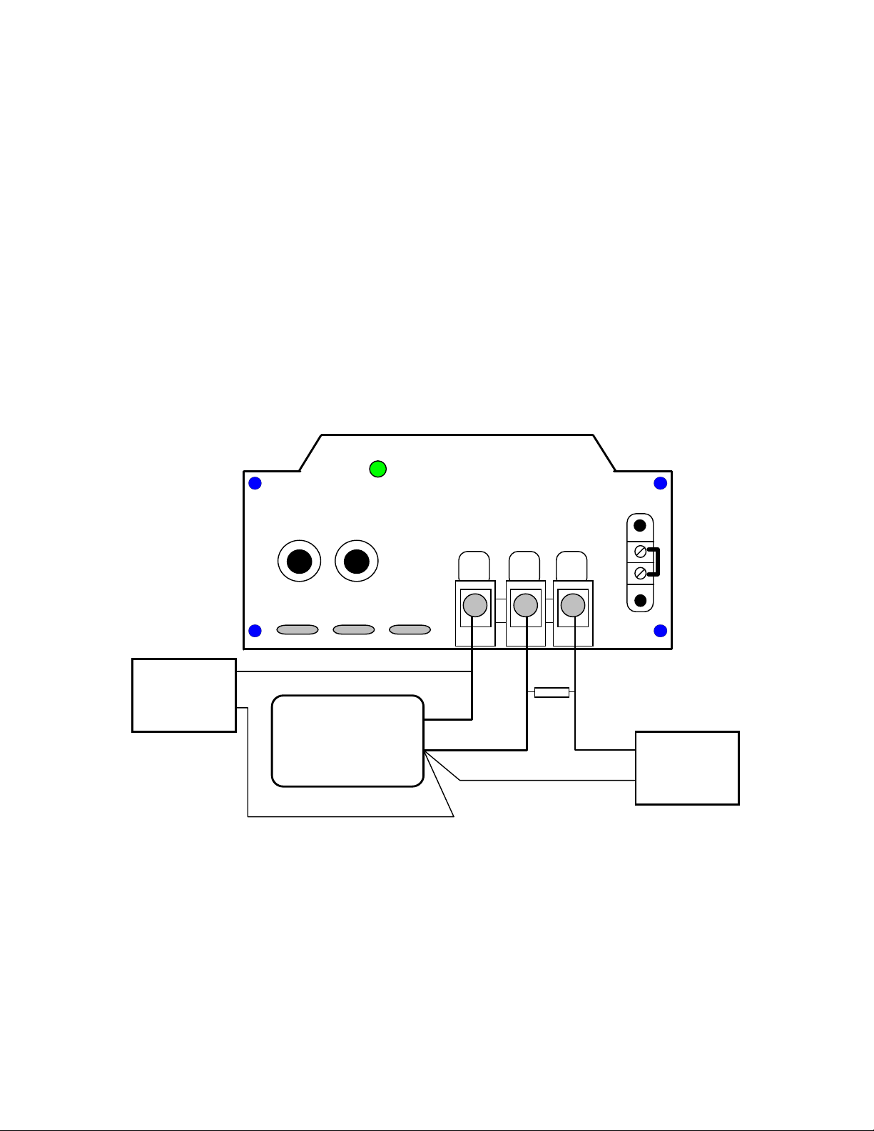
a) Hook up the unit to be adjusted as shown in Figure #3 under no load conditions:
5050
Input
12 VDC
Common
Ground
Output
24 VDC
Activity
Light
Circuit breakers
TBB
123
12
Power Supply
+12V
Ret
DVM
+24 V
Ret
Figure #3
TBA, 1 - enable / ignition
TBA, 2 - 12 VDC aux. TBA
1
2
b) Make sure terminals 1 & 2 on TBA are shorted and that the Power supply is turned off. Set the Digital
Volt Meter to the appropriate scale to read 24 VDC to two decimals.
c) Energize power supply and adjust its output voltage to +12 VDC. Adjust Potentiometer (B) to the
desired setting (between 24 VDC and 28 VDC) and observe converter voltage output reading on DVM
d) Turn off power supply.
Page 3
3.2) Low Input Voltage Cutout Adjustment
The Model 680CE is provided with a circuit to protect against destructively deep battery discharges, or
discharges beyond the point where the vehicle battery can no longer support ignition.
680CE’s are adjusted at the factory to the minimum low input voltage cutout (LIVC) of 10.8 V below
which the converter remains inactive. The low input voltage cutout (LIVC) may be readjusted to another
level using the test circuit in Figure #4. The LIVC functions such that when the vehicle voltage is drawn
below the LIVC, the converter shuts off and becomes dormant as the activity light extinguishes. In this
state the converter will feed its input voltage to its output. When in this state, in the event that a voltage
equal to or higher than the converter input should be superimposed on the output (e.g. a 24V battery
bank) the output configuration of the converter will prevent current from back feeding by presenting an
extremely high output impedance. An audible click can be heard and the activity light extinguishes as
the LIVC circuit turns off the converter. Its output voltage can be measured to drop from its normal
output voltage setting to approximately the source input voltage. The range of LIVC adjustment is 10.8
to 13.0 VDC.
The LVC adjustment set up is as shown in Figure #4.
5050
Input
12 VDC
Common
Return
Output
24 VDC
Activity
Light
Circuit breakers
TBB
123
12
Power Supply
+12V
Ret
DVM 2
Read Output +24 V
Ret
DVM 1
Read Input Cutout
Ret
Unit Under Adjustment
TBA, 1 - enable / ignition
TBA, 2 - 12 VDC aux. TBA
1
2
100 ohm, 10W
Load Resistor
R1 R1 =
Figure #4
a) Turn pot (A) completely clock wise
b) Activate converter by turning on the power supply and setting it to the desired cutout voltage
c) Very gradually turn pot (A) counter clockwise until simultaneously a click can be heard and the
activity light extinguishes accompanied by a drop in the reading on the DVM 2.
d) Adjustment is over.
There is approximately 0.8 Volt of Hysteresis between the cutout and turn on voltages of Model 680CE.
e.g. if 11 VDC is selected for cutout, that unit will turn back on when an input of at least 11.8 Volts is
reapplied. This design serves to prevent rapid fluttering as battery voltage recovers with load removal.
Page 4

IV Warranty and Repair
Should your investigations indicate that your new Model 680CE is defective or damaged and your unit
is still under warranty then contact SEC America Corp. at 802-865-8388 and obtain return merchandise
authorization for credit or exchange.
If the warranty period has expired or if the warranty has been violated due to operator error or misuse,
then call :
SEC America Corp., Repair Department, at 802-865-8388 or fax SEC America Corp. at 802-865-8389
to receive authorization for shipment back to factory for a survey and possible repair.
Warranty
The Model 680CE has a 2 year warranty covering parts and labor. The warranty is found below:
We warrant each instrument, sold by us, or our authorized agents, to be
free from defects in material and workmanship and that it will perform
within applicable specifications for a period of two years after original
shipment. Our obligation under this guarantee is limited to repairing or
replacing any instrument or any part thereof,except fuses and pilot lights,
which shall within one year after delivery to the original purchaser, be
returned to us with transportation charges prepaid, prove after our exa-
mination to be thus defective.
LIMITED WARRANTY
The above limited warranties take the place of all other warranties,
expressed or implied, and correction of such defects by replacement or
repair shall constitute a fulfillment of all obligations under the terms of the
warranties. The warranties do not cover any unit that has been damaged
either in transit or by misuse, accident or negligence. No warranty or re-
presentation by anyone other than this Company shall be binding on us.
To return a unit send only to the following address:
SEC America Corp
78 Ethan Allen Drive
S. Burlington, VT 05403
PLEASE RETAIN YOUR ORIGINAL BILL OF SALE. IT MUST
BE SUBMITTED WHEN MAKING ANY WARRANTY CLAIM
Page 5

V Base Plate Mechanical Drawing
SEC America, LLC
S. Burlington, VT 05407
REV
DWG. NO.
63-1448 C
0.215 dia. 4 places
1.250
6.430
0.400
1.650
10.500
0.580
13.800
0.625
3.930
5.430
0.869
0.468
45 deg. @ 0.400 from edges (4 places)
0.250
0.080
0.375
0.250
0.125 radius
4 places
0.250
0.200 dia.
4 places 0.562 0.625
0.125
CL
side view is symetric about
the center line
Page 6

VI Electrical Specifications:
Output Voltage: 26.4 Nominal (Internally adjustable +,- 0.5V)
Output Voltage Adjust Range 24.5 VDC to 28.0 VDC (internally adjustable)
Continuous Max Load Amps: 40 ADC @ 40C ambient (Input 12.5 Vdc)
40 ADC @ 60C ambient
Maximum Power Dissipation: 60 Watts @ Full Load (40A, 26.4 VDC out)
Maximum Input Current: 90 A (12 VDC in)
Overload Protection: Electronically current limited (primary protection)
Circuit Breakers at the Input (secondary protection)
Cooling: Convection or Forced Air
Thermostat Controlled Fan
Output Ripple Voltage: 10 mV RMS (20C to 75C)
50 mV RMS (-30C)
Input Voltage Range: 11 VDC to 15 VDC
Input Output Isolation: Input and Output returns (Ground) are Common
Low Voltage Cutout Circuit:
Low Voltage cutout point: Adjustable from 10.5 VDC to 13 VDC
(internally adjustable)
Low Voltage cutout Hysteresis: 1.2 VDC @ 13.0 V/ 0.9 VDC @ 10.5 VDC
Activation Circuits:
1) The unit may be activated through the command terminal #1 of terminal block TBA which
when connected to +12 VDC of the vehicle will turn on the converter.
2) The converter may be turned on in sections by using the circuit breakers on the front panel.
e.g. if only a 20 Amp load is required, section one only may be selected.
Ambient Operating Temperature: -30C to + 60C
Maximum Humidity: 100% non condensing
Maximum Elevation: 15000 ft. above sea level
Mechanical Specifications:
Dimensions: 13.7 L x 7.0W x 3.5 H (inches overall maximum)
Shipping Weight: 10 lb.
Construction: Steel base with Aluminum wrap around (painted)
Mounting Method: #12 Hardware via front and rear mounting flanges
Mounting Centers: 13.3 x 3.87 (inches)
Hook Up: 3 Position Splicer Terminal Blocks
Page 7
Table of contents
Other SEC America Media Converter manuals


Popular Media Converter manuals by other brands

ConnectGear
ConnectGear GC-H21MR user guide

Procon
Procon MelCOMMS MINI installation manual

Chauvet Professional
Chauvet Professional VIP DRIVE 10-5 Nova user manual

Euromag
Euromag MC608 Series instruction manual
 user guide")
Transition Networks
Transition Networks E-PSW-FX-03(LH) user guide

Motrona
Motrona GV224 operating manual


