System
These RF receivers are compatible with both code hopping and fixed-code transmitters (see page 4 of this manual for
a list of compatible transmitters). They can be used for a variety of applications, such as allowing the same transmitter to
arm/disarm a vehicle alarm and open/close a garage door opener. The receivers come in one- or two-channel
versions. Each channel can learn the codes of up to 15 different transmitter buttons on a first-in, first-out basis.
Installation Notes
1. Mount out of sight in a location where it is not surrounded by metal, and where it is not exposed to the weather or
moisture. Metal will block the RF signal, resulting in a reduced range.
2. For best range, pull the antenna wire as long and straight as possible. If the receiver receives interference from
local RF activity (e.g.., airport or military base), the antenna wire can be folded. DO NOT CUT THE ANTENNA WIRE.
Learning a New Button Code (channel 1)
1. Press mode switch #1 for three seconds. The green LED will start to flash quickly.
2. While the green LED is flashing quickly, press a button on a compatible transmitter. The green LED will flash once
and then turn off to show that that button was learned.
3. Repeat steps 1 and 2 to learn more buttons into channel 1.
NOTE — The green LED will flash a maximum of 15 seconds. If no transmitter button is pressed during this time, the
receiver will exit the code-learning mode, and the green LED will turn off.
Learning a New Button Code (channel 2)
The procedure is the same as for channel 1, except mode switch #2 initiates the code-learning process, and the red
LED shows status.
Note Regarding Code Learning
1. The receiver will only learn the code of a particular button once. Once a button’s code is learned, if you try to
code-learn that button again, whether it is for the same channel or not, the receiver will exit code learning mode.
2. Each channel can learn the codes of a maximum of 15 transmitter buttons. If you attempt to learn a sixteenth
button, the earliest code learned will be deleted.
3. To clear all codes — Press the appropriate mode switch (#1 or #2) for three seconds. When the LED starts
flashing, press that switch again for three seconds. The LED flashes twice to indicate that all codes associated
with that channel are now deleted.
Programming Relay Output Modes
The relay output(s) can be programmed for one of four different modes, depending on the application:
• 4-second momentary — Press the transmitter button once. The relay turns on for 4 seconds, and then turns off.
(This is the DEFAULT mode)
• 1-second momentary — Press the transmitter button once. The relay turns on for 1 second, and then turns off.
• Toggle — Press the transmitter button once, and the relay turns on. Press a compatible transmitter button again,
and the relay turns off.
• Validity — The relay turns on for as long as the transmitter button is pressed.
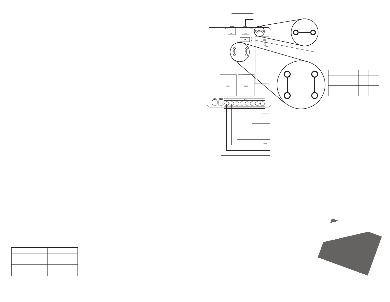
To program outputs, open case and find the 2 jumpers marked LP1 and LP2. Cut these jumpers, if needed, as shown
on Table 1:
NOTE — On the 2-channel models, the output mode of both relays is the same. In other words, you cannot have
4-second momentary output for channel 1 and latch output for channel 2.
CH 2 DRY RELAY COM
CH 2 DRY RELAY NC
CH 2 DRY RELAY NO
CH 1 DRY RELAY COM
CH 1 DRY RELAY NC
CH 1 DRY RELAY NO
CH 2 STATUS LED - SK-910R2Q only
CH 1 STATUS LED
MODE SWITCH #1
MODE SWITCH #2
}(SK-910R2Q only)
LP1
LP2
LP3
(see Below)
Output type LP1 LP2
4-second momentary Uncut Uncut
1-second momentary Uncut Cut
Toggle Cut Uncut
Validity Cut Cut
Three-Pin Antenna Port
(see Extended Range Antennas below)
Output Program Loops
Antenna Program Loop
(see Extended Range Antennas below)
Extended Range Antennas
Two antennas are now available for range extension of the SK-910 receivers:
SK-91ERSWQ Extends RF receiver range up to 900 feet (open air) with existing remote.
SK-91ERSDQ Extends RF receiver range up to 1600 feet (open air) with existing remote.
These antennas come with a 9’ cable which easily plugs into the 3-pin antenna port located on the RF receiver
(See SK-910RQ/R2Q PC board diagram - above).
Note:
If an extended range antenna is used with either receiver, the loop on the receiver PC board marked “LP3” must be cut.
Mode Switch Operation (one per channel)
• Learn mode — Press and hold the switch for three seconds.
• Clear memory — Press three seconds, then when the LED starts flashing, press again for three seconds to delete
all previously learned codes.
• Memory Display — Press and release the mode switch to show number of codes stored. LED will flash a number
of times to correspond to the number of codes stored.
LED Indication (one per channel)
• Steady on — Senses signal from a transmitter button whose code was already learned.
• Fast flash — In the code-learning mode.
• One flash — A transmitter button code was learned.
• Two flashes — All previously learned
transmitter button codes were deleted.
SK-91ERSWQ
SK-91ERSDQ
+}POWER INPUT (see General Specifications on the back page)
Output type LP1 LP2
4-second momentary Uncut Uncut
1-second momentary Uncut Cut
Toggle Cut Uncut
Validity Cut Cut
Table 1 – Programming relay output modes


