Amphenol Procom PRO-DAR4 User manual

User Manual
19” Rack-mountable
Dual Amplifier Receiver Multicoupler
type
PRO-DAR4
PRO-DAR8
PRO-DAR12
PRO-DAR16

Page 2 of 15
Title:
User Manual for 19” Rack-mountable Dual Amplifier Receiver Multicoupler models PRO-DAR
(4, 8, 12 or 16 channels)
Document version:
Reviewed: 1r3
Document Change Record
Issue
Date
Sheet (s)
Description of change
Alterations
endorsed and
implemented by
1r0
31-05-2023
All
First release
SMN
1r1
23-06-2023
Page 12
Connection of Power supply voltage
SMN
1r3
04-09-2023
All
Div. corrections
SMN
Amphenol Procom Contacts:
Adnan Ahmad
Director of Engineering
Customer service
Phone: (+45) 48 27 84 84
Direct: (+45) 48 27 02 77
aa@amphenolprocom.com
dksales@amphenolprocom.com
EU and UK DECLARATION OF CONFORMITY
Hereby Amphenol Procom declare that the product of PRO-DAR models is in compliance with EU Directive
2014/53/EU and the UK Radio Equipment Regulations 2017 (S.I. 2017 No. 1206).
The full text of the Declaration of Conformity is available at:
https://amphenolprocom.com/images/shop/catalog/pdf-for-catalouges/Declaration-of-Conformity-PRO-DAR.pdf

Page 3 of 15
List of Contents
1Preface..............................................................................................................................4
2Safety precautions.............................................................................................................4
2.1 Environment...............................................................................................................4
2.2 Protective earth..........................................................................................................4
2.3 Equipotential bonding.................................................................................................4
2.4 Fuses .........................................................................................................................4
2.5 Power on/off...............................................................................................................4
2.6 Reading this manual...................................................................................................5
3Introduction........................................................................................................................5
4Technical Specifications ....................................................................................................5
5Block Diagrams..................................................................................................................6
5.1 Block diagram PRO-DAR4 .........................................................................................6
5.2 Block diagram PRO-DAR8 .........................................................................................6
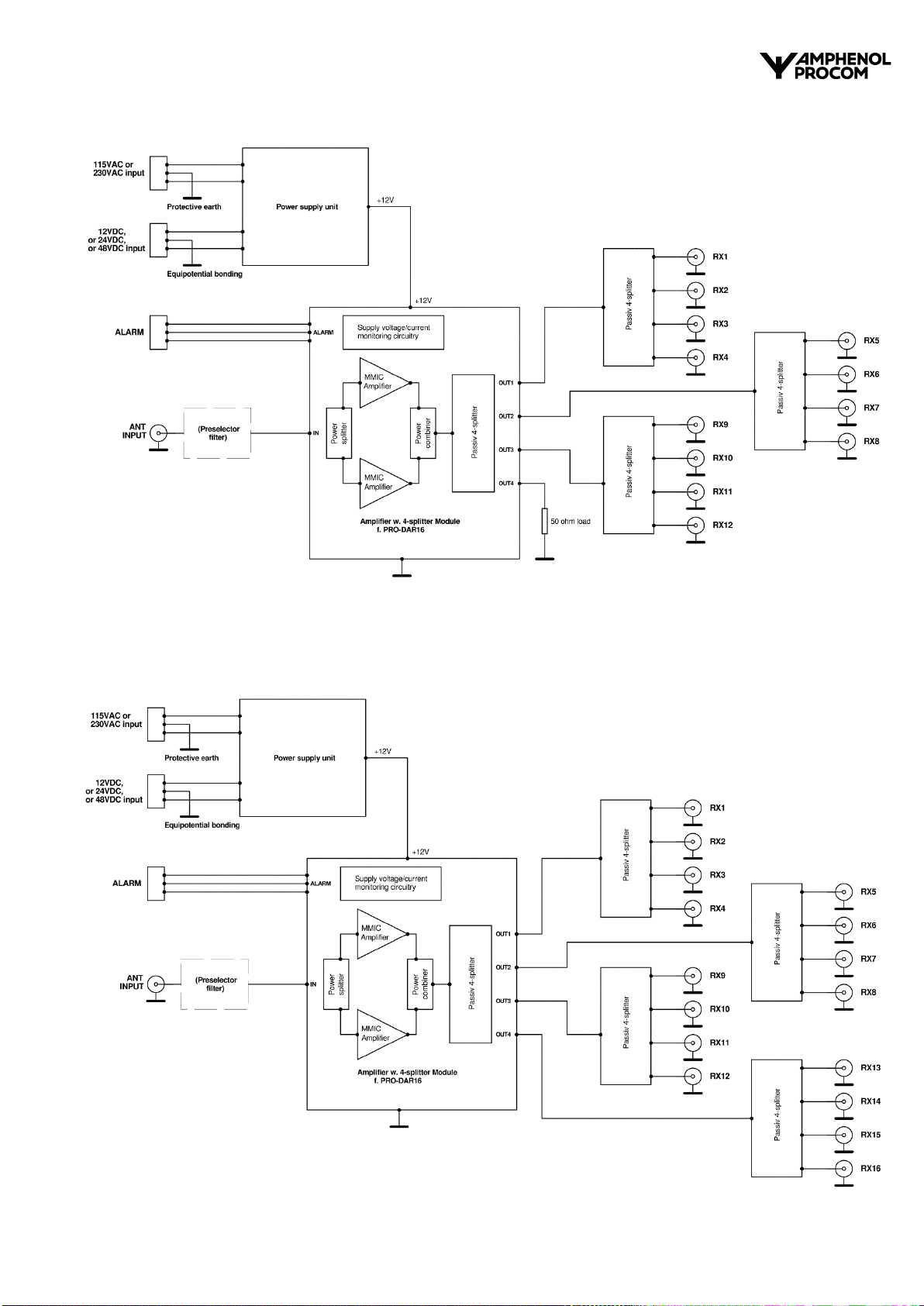
5.3 Block diagram PRO-DAR12 .......................................................................................7
5.4 Block diagram PRO-DAR16 .......................................................................................7
6Circuit description..............................................................................................................8
6.1 Amplifier/splitter modules............................................................................................8
6.2 Alarm system..............................................................................................................9
6.3 Preselector (option)....................................................................................................9
6.4 Power supply............................................................................................................10
6.4.1 Power supply Block Diagram....................................................................................10
6.5 Power supply backup function..................................................................................10
7Installation .......................................................................................................................11
7.1 Front view.................................................................................................................11
7.2 Rear view.................................................................................................................11
7.2.1 Rear view PRO-DAR4.......................................................................................11
7.2.2 Rear view PRO-DAR8.......................................................................................12
7.2.3 Rear view PRO-DAR12.....................................................................................12
7.2.4 Rear view PRO-DAR16.....................................................................................12
7.3 Connection of power supply voltage.........................................................................12
7.3.1 Mains power connection....................................................................................12
7.3.2 Protective earth.................................................................................................13
7.3.3 DC power connection........................................................................................13
7.4 Equipotential bonding...............................................................................................13
7.5 Functional earth........................................................................................................14
7.6 Connection of alarm .................................................................................................14
7.7 Connection of antenna .............................................................................................14
7.8 Connection of receivers............................................................................................14
7.9 Mounting ..................................................................................................................14
8Operating instructions......................................................................................................14
8.1 POWER LED............................................................................................................14
8.2 Maintenance.............................................................................................................14
9Trouble shooting..............................................................................................................15
9.1 Spare Parts ..............................................................................................................15

Page 4 of 15
1 Preface
This user manual covers the Amphenol Procom Dual Amplifier Receiver Multicoupler
models: PRO-DAR4, PRO-DAR8, PRO-DAR12 and PRO-DAR16.
In the subsequent chapters, for the sake of clarity:
Where the descriptions are valid for all 4 receiver multicoupler models where each model
also comes in different versions depending on e.g., how many Rx-ports are in operation, or
preselector used etc., the figure in the model designation is replaced by “PRO-DAR
versions”.
2 Safety precautions
2.1 Environment
The PRO-DAR versions are intended for indoor use only.
Do not allow the unit to be wet.
Do not operate the unit at temperatures outside the specified range -10 C to +60 C.
Do not place the unit in a corrosive environment.
2.2 Protective earth
The main earthing point is the center contact of the IEC60320-1 C14 mains power inlet.
See chapter 7.2, 7.3 and 7.3.2.
Connection to protective earth is provided via the 3-wire IEC mains power cord.
As safety relies on connection to protective earth,
the PRO-DAR versions must be connected to an earthed mains socket-outlet.
2.3 Equipotential bonding
It is strongly recommended that all interconnected conductive accessible parts in a
system are connected to an equipotential bonding system.
The center terminal of the 3-pole terminal block for DC supply connection on the rear side
is intended for equipotential bonding. See chapter 7.2 and 7.4.
2.4 Fuses
Individual fuses are provided for both the mains voltage and the DC voltage.
The fuse holders are located on the rear side next to the supply voltage connectors.
On the top plate next to the fuse holders are marked the fuse specifications.
To maintain the safety level, a blown fuse must be replaced by a fuse of equal size,
type and value. Refer to chapter 9.1: “Spare parts”.
2.5 Power on/off
No power on/off switch is provided on the PRO-DAR versions.
Therefore, as soon as power is connected, the equipment will be immediately active
and the POWER LED on the front plate will light green, indicating power is on.
The mains power cord (mains plug or socket) serves as a mains switch and
either plug or socket of the cord must be easily accessible.
This equipment is not suitable for use in locations
where children is likely to be present.

Page 5 of 15
2.6 Reading this manual
Before installing or replacing of the PRO-DAR versions, this entire manual should be read
and understood. Incorrect installation and usage may damage the equipment.
3 Introduction
The typical function of an active receiver multicoupler is to distribute a received antenna
signal to a number of receivers,
without introducing any signal loss and interacting between the receivers.
A passive power splitter could be used to split the antenna signal for the required number of
receivers. However, this way each receiver will only get a part of the received signal power,
and the sensitivity of the individual receivers will be reduced.
If an active low-noise receiver multicoupler is used for antenna signal distribution,
an antenna signal virtually identical to the original one will be applied to each receiver,
as if the particular receiver was directly connected to the antenna exclusively.
This manual contains description, installation, and documentation of the Amphenol Procom
models PRO-DAR4, PRO-DAR8, PRO-DAR12 and PRO-DAR16, which are active receiver
multicouplers with one input (ANT) intended for connection of RF signal (antenna signal) and
4, 8, 12 or 16 identical outputs (RX1 to RX4/8/12/16) intended to provide RF signal (antenna
signal) for a similar number of individual receivers.
PRO-DAR models cover the frequency range 30 MHz to 960 MHz and can be used at any
frequency or frequency band within this range.
The PRO-DAR models of multicouplers can also be used for buffering and splitting any other
kind of RF signal within the specified signal dynamic range of the equipment.
4 Technical Specifications
Please refer to the PRO-DAR datasheet on www.amphenolprocom.com

Page 6 of 15
5 Block Diagrams
5.1 Block diagram PRO-DAR4
5.2 Block diagram PRO-DAR8

Page 7 of 15
5.3 Block diagram PRO-DAR12
5.4 Block diagram PRO-DAR16

Page 8 of 15
6 Circuit description
6.1 Amplifier/splitter modules
The PRO-DAR multicouplers contains a dedicated RF amplifier system, followed by
a passive n-way power splitter circuitry corresponding to the particular number of outputs.
The RF amplifier system compensates for the n-way splitter loss + circuitry insertion loss.
The RF amplifier system is of the redundant type. It is designed as 2 separate identical
amplifier stages, which operates in parallel.
On the amplifier input the RF signal is divided in 2 identical portions in a 2-way power
splitter, and the signal from each splitter output is fed to the input of the 2 amplifier stages.
On the amplifier output, the output signal from each amplifier stage is combined in a
2-way power combiner.
This redundant RF amplifier design provides maximum operational reliability for the
multicoupler. If one of the amplifier stages fails, the amplifier will continue to operate with
gain around -6 dB relative to the normal gain, providing uninterrupted service with only
minor performance deterioration.
The RF amplifier has low noise figure to ensure lowest possible signal-to-noise ratio
deterioration of the distributed RX signal.
Simultaneously, the RF amplifier has very good large signal capabilities, in order to avoid
intermodulation between strong signals in the distributed RF signal spectrum.
Moreover, paralleling of two amplifier stages provides further increased amplifier dynamic
range compared to a similar single stage amplifier design.
The output signal from the amplifier system is fed to an n-way passive power splitter
circuitry, where n corresponds to the number of outputs of the particular multicoupler.
The PRO-DAR4 is provided with a 4-splitter circuitry at the output. The 4 outputs from the
splitter form the 4 identical RX outputs.
The PRO-DAR8 is provided with a 2-splitter, followed by 2 identical 4-splitters, which forms
the 8 identical RX outputs.
The PRO-DAR12 and PRO-DAR16 are provided with a 4-splitter, followed by 3 or 4
identical 4-splitters, which forms the 12 or 16 identical RX outputs.
The power splitter circuitry is of the Wilkinson type and provides high isolation between the
individual RX outputs, ensuring insignificant low mutual coupling between the connected
receivers.
Gain of the amplifier is adjusted individually to compensate for the particular loss in the
different splitter systems.
See chapter 5: Block diagrams.
In order to maintain a high input dynamic range of the connected receivers (ability to
withstand strong antenna signals), RF gain from ANT input to RX output is selected to be
low, nominally +2 dB.
This gain value is factory adjusted and gain adjustment is not user accessible.
RF amplifier and power splitter circuitry are of wideband structure, meaning that signals in
the whole frequency range from 30 MHz to 960 MHz will be amplified equally.

Page 9 of 15
6.2 Alarm system
The RF amplifier system is provided with an alarm function, which monitors the DC
voltage/current of the 2 RF amplifier stages in the redundant amplifier system.
The functional status is given by means of 2 different indications:
1. The POWER LED on the front plate, which will light constantly with green light,
if the amplifier condition is OK. If a fault occurs in the RF amplifier system, the LED will
light with flashing red light.
2. A floating relay switch-over contact, which is connected to the alarm connector on the
rear side of the multicoupler.
This relay contact has a defined position if the condition of the 2 amplifier stages is OK.
If a fault occurs, the relay contact will switch over to the opposite position, thus indicating
a failure condition.
The position of the relay contact can be remotely read via the alarm connector.
Alarm relay normal condition Alarm relay failure condition
In normal condition, the C (Common) and the NC (Normally Closed) terminals are
connected.
In failure condition, the C (Common) and the NO (Normally Open) terminals are connected.
The relay contact is floating, that is, the contact, the wiring and the alarm connector are
electrically isolated from ground and the remaining circuitry.
The relay contact is rated to 60 V and 2 A DC.
6.3 Preselector (option)
If the receiver multicoupler shall operate within a narrower specified frequency band, it will
be advantageous to insert a preselector filter with pass range equal to the frequency band of
interest between the multicoupler ANT input and the RF amplifier.
The preselector filter will allow the wanted frequency band to pass and simultaneously
attenuate all signals outside this band, thus reducing the risk of possible interference from
strong unwanted out-of-band signals.
If desired, the PRO-DAR models can be ordered with a costumer selected factory built-in
preselector filter. Amphenol Procom offers a large number of standard low-loss filters, which
are suitable as multicoupler preselector.
An overview of available filters suitable for preselector is found on the PRO-DAR datasheet
on www.amphenolprocom.dk

Page 10 of 15
6.4 Power supply
The PRO-DAR versions are provided with a power supply unit which supplies DC voltage
for the RF amplifier module.
The power supply unit both can operate with 230 or 115 VAC mains voltage and with 12 or
24 or 48 VDC, depending on model.
The AC mains voltage directly feeds a mains voltage winding on the mains transformer,
The DC voltage feeds a 50 Hz power multivibrator circuitry, which supplies a 50 Hz square
wave to a low voltage winding on the mains transformer.
Another low-voltage winding feeds AC voltage to a rectifier and voltage regulator circuitry.
The voltage regulator output supplies 12 VDC to the RF amplifier module.
As both the mains supply voltage and the DC supply voltage thus are fully galvanically
separated from the amplifier supply voltage by the mains transformer, unwanted ground
loops etc. are avoided.
6.4.1 Power supply Block Diagram
6.5 Power supply backup function
The power supply unit is provided with backup function.
If DC voltage (12, 24 or 48 VDC depending on model) from e.g., a rechargeable battery is
connected to the multicoupler together with AC mains voltage, the DC voltage source will
function as power backup.
If AC mains supply voltage is applied to the multicoupler, the relays are activated, and the
relay contact setting will connect mains voltage to the transformer and the DC supply
voltage input will be switched off.
The mains voltage thus has priority, and the multicoupler will operate on the mains voltage
if present, independent of DC voltage is connected or not.
If the mains voltage falls out, the relays are deactivated, and the contact setting will
disconnect the mains voltage input and connect DC supply voltage to the power
multivibrator, which then feeds low-voltage AC to a separate winding on the transformer,
and the multicoupler will continue to operate.
This automatic power switch-over function thus ensures an uninterrupted service of the
multicoupler, in case of mains power outage.

Page 11 of 15
The multicoupler can of course also operate directly on the DC supply voltage only,
if no mains supply voltage is provided.
If both mains AC supply and DC supply fail, the multicoupler is completely de-energized,
the floating alarm relay switch-over contact will also be toggled to indicate fault condition.
The POWER ON / operating status LED will then be off in this situation.
7 Installation
7.1 Front view
The front plate is identical on all 4 receiver multicoupler models, except for the height:
PRO-DAR4 and PRO-DAR8 are 1HU (44.45 mm) high.
PRO-DAR12 and PRO-DAR16 are 2HU (89.9 mm) high.
Below is shown the front view of the PRO-DAR4/PRO-DAR8.
The front plate is provided with 2 pcs. 7 x 10 mm oval mounting holes in each side, intended
for rack mounting of the multicoupler, using M6 screws.
Further, a POWER ON LED is provided.
Front view of PRO-DAR4/PRO-DAR8:
7.2 Rear view
The rear panel of the multicouplers is provided with ANT and RX RF connectors,
mains power and DC power inlets, alarm connector, and holders for both mains and DC
fuses.
Below is shown the rear view of the 4 multicoupler models:
7.2.1 Rear view PRO-DAR4
(Protective
earth)
ANT
RX1 RX2 RX3 RX4
Mains
fuse
Mains
power inlet
(Equipotential bonding /
Functional earth)
POWER
Receiver Distribution Panel
POWER ON LED
Mounting
holes
Mounting
holes
DC
power
inlet
DC
fuse
+ –
Alarm
output

Page 12 of 15
7.2.2 Rear view PRO-DAR8
7.2.3 Rear view PRO-DAR12
7.2.4 Rear view PRO-DAR16
7.3 Connection of power supply voltage
7.3.1 Mains power connection
When operating on mains supply voltage, the PRO-DAR models are to be considered as a
class I product with requirement of connection to protective earth.
The PRO-DAR models are provided with a 3-terminal IEC60320-1 C14 (male) inlet for
mains power connection. The mains inlet is located on the rear side. See rear view above.
Applied mains voltage must be within the range:
230 VAC models:
198 –264 VAC (220 –240 V ±10 %)
115 VAC models:
99 –132 VAC (110 –120 V ±10 %)
AC frequency:
Within 47 to 63 Hz
(Protective
earth)
ANT
RX1 RX2 RX3 RX4 RX5 RX6 RX7 RX8
Mains
power inlet
(Protective
earth)
RX9 RX10 RX11 RX12
RX1 RX2 RX3 RX4 RX5 RX6 RX7 RX8
Mains
power
inlet
ANT
(Protective
earth)
RX9 RX10 RX11 RX12 RX13 RX14 RX15 RX16
RX1 RX2 RX3 RX4 RX5 RX6 RX7 RX8
Mains
power
inlet
ANT
DC
power
inlet
DC
fuse
Mains
fuse
+ –
+ –
DC
fuse
Mains
fuse
DC
power
inlet
+ –
DC
power
inlet
DC
fuse
Mains
fuse
Alarm
output
Alarm
output
Alarm
output
(Equipotential bonding /
Functional earth)
(Equipotential bonding /
Functional earth)
(Equipotential bonding /
Functional earth)

Page 13 of 15
A 3-wire IEC power cord must be used for mains voltage connection.
7.3.2 Protective earth
The main earthing point is the center contact of the mains power inlet.
See rear view above in section 7.2.
Connection to protective earth is provided via the 3-wire IEC power cord.
The PRO-DAR models therefore must be connected to an earthed mains socket-outlet.
7.3.3 DC power connection
When operating on DC supply voltage as back-up power, together with mains supply
voltage, the PRO-DAR models are to be considered as a class I product with requirement of
connection to protective earth.
In this situation, connection to protective earth is provided via the mains power 3-wire
IEC power cord.
When operating on DC supply voltage exclusively, without mains supply connection,
the PRO-DAR models are to be considered as a class III product with no requirement of
connection to protective earth.
The PRO-DAR models are provided with a 3 pole Phoenix 7.62 mm header/plug
(DC inlet) for connection of 12 VDC, 24 VDC or 48 VDC voltage (depending on model).
The Phoenix header/plug is located on the rear side.
See rear view above in section 7.2.
Regarding Phoenix 7.62 mm cable connector, see chapter 9.1: “Spare parts”.
Applied DC voltage must be within the range:
12 VDC models:
10.8 –14.4 VDC
24 VDC models:
20 –32 VDC
48 VDC models:
40 –60 VDC
On the top plate next to the Phoenix header/plug are indicated the polarity of the
terminals:
DC supply voltage (if used) must be applied correctly to the PRO-DAR multicoupler.
If the polarization of the applied DC voltage is wrong, the DC fuse will blow.
The fuse must be replaced by a fuse according to chapter 9.1: “Spare parts”.
7.4 Equipotential bonding
The center terminal of the 3-pole terminal block marked is intended for equipotential
bonding.
It is strongly recommended that all interconnected conductive accessible parts in a
system are connected to an equipotential bonding system, in order that no hazardous
touch voltage appears on exposed conductive parts.
+ –

Page 14 of 15
7.5 Functional earth
The center terminal of the 3-pole terminal block marked can be used as
functional earth as well, when needed.
7.6 Connection of alarm
The alarm output provides connection to a relay switch-over contact, which setting
indicates the operating condition of the RF amplifier system.
The alarm output is provided with a 3 pole Phoenix 5.08 mm header/plug.
The Phoenix header/plug is located on the rear side.
See rear view above in section 7.2.
Regarding Phoenix 5.08 mm cable connector, see chapter 9.1: “Spare parts”.
7.7 Connection of antenna
The antenna (or other RF source) shall be connected to the input connector marked
“ANT” on the rear edge of the PRO-DAR multicoupler top plate by means of a suitable
coax cable.
Be aware that the maximum RF input level of +23 dBm is not exceeded, in order to avoid
damaging of the RF amplifier.
As the ANT connector shield is connected to chassis, the coax cable shield will
automatically be connected to protective earth and be included in the equipotential
bonding (if used).
7.8 Connection of receivers
The individual receivers’ antenna inputs (RF inputs) shall be connected by a suitable coax
cable to the output connectors marked “RX1 to 4”, “RX1 to 8” “RX1 to 12” or “RX1 to 16”
(depending on model) on the rear edge of the PRO-DAR multicoupler top plate.
If the PRO-DAR multicoupler has unused RX output ports, these should be terminated
with a 50
dummy load
(min. 250 mW).
7.9 Mounting
By rack mounting, screws must be mounted in all 4 mounting holes in the front plate.
When mounted in a fully enclosed cabinet,
adequate ventilation or heat path shall be provided in order to keep the air temperature round
the multicoupler housing below +60 C.
8 Operating instructions
As soon as mains supply voltage or DC supply voltage is applied to a PRO-DAR multicoupler,
it will be immediately active.
Normal operational conditions do not require any adjustments or settings of the multicoupler.
8.1 POWER LED
When power is connected to a PRO-DAR, the POWER LED on the front plate will
immediately light with green color and indicate the multicoupler is active.
8.2 Maintenance
No maintenance of the PRO-DAR models is normally needed.

Page 15 of 15
However, if any malfunction of the multicoupler RF amplifier system occurs, the POWER LED
on the front plate will immediately light with flashing red color and indicate that some fault
condition has occurred.
Please refer to chapter 9: “Trouble shooting” below.
If the instructions in the Trouble shooting chapter is insufficient, please contact nearest
PROCOM dealer or Amphenol Procom for further information.
9 Trouble shooting
9.1 Spare Parts
Article
Value
Amphenol
Procom
Spare part no.
Fuse for 230 VAC
T315mAL250V 5x20 mm
661001008
Fuse for 115 VAC
T500mAL250V 5x20 mm
661001096
Fuse for 12 VDC/24 VDC
T2AL250V 5x20 mm
661000047
Fuse for 48 VDC
T315mAL250V 5x20 mm
661001008
Phoenix cable connector 7.62 mm
female for DC supply connection
662001103
Phoenix cable connector 5.08 mm
female for ALARM connection
662001102
Symptom
Possible cause
Action
POWER LED off
Supply voltage not
connected or off.
Connect supply voltage.
AC or DC fuse blown,
POWER LED off
Check and replace fuse(s).
AC fuse blown
Internal circuitry fault
Contact Amphenol Procom.
DC fuse blown
By DC voltage
operation, wrong DC
polarity.
Check DC voltage and polarity and
reverse connections if necessary.
Reduced receiver
sensitivity
Supply voltage not
connected or off.
Connect supply voltage.
POWER LED lights
with flashing red light
Internal amplifier fault
Contact Amphenol Procom.
Other fault symptoms
Contact Amphenol Procom.
This manual suits for next models
3
Table of contents