second sound ACO160 User manual

ACO160
Deluxe Audio-Controlled Oscillator
1 999 SW 1st Ave. #1617, Miami, FL 33130
ACO160 Audio Controlled Oscillator
•Direct audio to analog
square/sawtooth/sine oscillator output
•1V/octave pitch CV output (with
calibrated post-amplifier)
•Rail-to-rail output zero-ripple envelope
follower
•Modulation CV input with +/-2 octave
range and semitone resolution
•Hard sync input for internal audio
oscillators
•Gate output with user-configurable
threshold
•“Track” input enables freezing of pitch
when input is weak
•Fully balanced audio signal path
•Support for MIDI out with additional uC
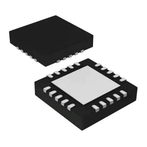
•7mm x 7mm 32-pin LQFP
•25mA max current consumption from
4.5-5.5v supply
•One-cycle latency
•25Hz-5.2kHz frequency tracking range
Applications
•Audio-controlled modular and semi-
modular synthesizers
•Pitch-to-CV converters
•Harmonizers
•Guitar and other instrument
effects/stompboxes
Description
The ACO160 audio-controlled oscillator is an
ultra-low latency, low-power frequency-tracking
oscillator suitable for audio-controlled music
synthesizer applications. It contains a
fundamental frequency detector based on dual
switched-capacitor peak detectors with
frequency-dependent decay time for ultra-wide
detection range, ultrasonic analog oscillator and
frequency tracking engine that forces the
analog oscillator to run at 8192 times the
frequency of the incoming audio signal detected
at the input. This ultrasonic analog oscillator is
then divided back down to audio range using
programmable dividers that are controlled by
the harmony CV input and which cover a +/-2
octave range with semitone precision over the
entire range.
Additionally, the ACO160 features an integrated
switched-capacitor envelope follower which
exhibits zero ripple, even for the lowest
frequency signals the chip can detect (down to
25Hz). An integrated gate generation
comparator has the envelope signal wired to its
positive input and allows the user to set the
voltage on the negative input. This voltage
functions as the gate threshold and generates a
rail-to-rail gate CV output.
The ACO160 consumes only 25mA max from a
4.5-5.5V power supply, making it ideal for
battery-powered applications. Together with
other signal conditioning blocks such as a VCA,
VCF, PWM, the ACO100 can provide a complete
low-power analog audio-controlled synthesizer
solution.
For digital synth applications, the internal 16-bit
frequency detected by the chip is transmitted
via an SPI interface for easy processing by a
micro-controller. Together with the envelope
and gate outputs, it is easy to convert this
information into MIDI commands for controlling
digital synths with short enough latency to
satisfy even the most demanding real-time
applications.
Ordering Information
Part Number
Package
Body Size
ACO160
LQFP-32
7mm x 7mm

ACO160
Deluxe Audio-Controlled Oscillator
2 999 SW 1st Ave. #1617, Miami, FL 33130
Simplified Block Diagram
32-pin TQFP pinout
ACO160 Pins
Pin
Name
Direction
Description
1
VDDH
Supply
4.5-5.5v I/O supply
2
PITCH
Out
Pitch CV out at approximately 0.42v/oct
3
VDDA
Supply
3.3v analog supply, bypass with 1.0-2.2uF ceramic capacitor
4
RSTN
Input
0-VDDH Asynchronous active low reset
5
VSS
Supply
Ground
6
ASCAP
Input
Tuning input for DC offset of PITCH output, tunable from VSS to VDDH
in 8 discrete steps
7
VDDH
Supply
4.5-5.5v I/O supply
8
VSS
Supply
Ground
9
10
MODE0/
MODE1
Input
0-VDDH, sets ACO160 mode: MODE1/0 = 00: Test mode only
MODE1/0 = 01: CK1024, audio on
MODE1/0 = 10: MIDI on, audio off
MODE1/0 = 11: MIDI, audio both on
11
SYNC
Input
0-VDDH input with hysteresis around VDDH/2 to hard sync analog
oscillator outputs, can AC couple to VDDH/2
12
FTRACK
Input
Set to VDDH to enable frequency tracking, set to 0v to freeze current
pitch. Can tie to GATE output for intelligent pitch freeze operation.
13
SQUARE
Output
0-VDDA Square wave output
14
SAW
Output
0-VDDA Sawtooth wave output

ACO160
Deluxe Audio-Controlled Oscillator
3 999 SW 1st Ave. #1617, Miami, FL 33130
Pin
Name
Direction
Description
15
SIN
Output
0-VDDA Sine wave output level-shifted up by about 1v.
16
SINFILT
In/Out
0-VDDA Filter node for sine wave, bypass this pin to ground with a
100pF capacitor close to the chip
17
VSS
Supply
Ground
18
AHARM
Input
Harmony CV input: 0v = -2 octaves; VDDA = +2 octaves; in between,
tunes to the nearest semitone on the chromatic equal-tempered scale
19
VSS
Supply
Ground
20
FLL/SCLK
Output
0-VDDA: In MIDI mode (MODE1 = 1), SPI clock (SCLK)
In synchronous sample clock mode (MODE1/0 = 00), ACO output
divided down by the appropriate power of two to give a sample
frequency roughly between 100kHz and 200kHz
In analog-only synth mode (MODE1/0 = 01), quiet
21
DOWN/N
SS
Output
0-VDDA: In MIDI mode (MODE1 = 1), SPI active-low enable (NSS)
In synchronous sample clock mode (MODE1/0 = 00), single pulse over
one cycle of FLL output when the sample frequency drops by 2x
In analog-only synth mode (MODE1/0 = 01), quiet
22
UP/MOSI
Output
0-VDDA: In MIDI mode (MODE1 = 1), SPI master out slave in (MOSI)
In synchronous sample clock mode (MODE1/0 = 00), single pulse over
one cycle of FLL output when the sample frequency increases by 2x
In analog-only synth mode (MODE1/0 = 01), CK1024 clock running
1024x the input signal frequency (for external SC filters)
23
VDDD
Supply
3.3v digital supply, bypass with 1.0-2.2uF ceramic capacitor and
connect to VDDA on the PCB
24
VSS
Supply
Ground
25
ARATE
Input
Analog input for envelope follower rate control:
0v-VDDH/8: envelope decays to 32% of its initial value in one cycle
VDDH/8-2*VDDH/8: envelope decays to 45% of its value in one cycle
2*VDDH/8-3*VDDH/8: envelope decays to 56% of its value in one cycle
3*VDDH/8-4*VDDH/8: envelope decays to 67% of its value in one cycle
4*VDDH/8-5*VDDH/8: envelope decays to 75% of its value in one cycle
5*VDDH/8-6*VDDH/8: envelope decays to 82% of its value in one cycle
6*VDDH/8-7*VDDH/8: envelope decays to 86% of its value in one cycle
7*VDDH/8-VDDH: envelope decays to 90% of its value in one cycle
26
ACINN
Input
0-VDDH negative polarity audio input
27
ACINP
Input
0-VDDH positive polarity audio input
28
THRESH
Input
0-VDDA analog gate threshold input
29
ENV
Output
0-VDDH analog envelope follower output
30
GATE
Output
Gate output; When ENV output exceeds THRESH voltage, Gate = VDDH;
When ENV output is below THRESH voltage, GATE = 0v. Internal
hysteresis is included to avoid double toggling when GATE changes
state.
31
VSS
Supply
Ground
32
VDDH
Supply
4.5-5.5v I/O supply

ACO160
Deluxe Audio-Controlled Oscillator
4 999 SW 1st Ave. #1617, Miami, FL 33130
Package Information for 32-pin LQFP
Other second sound Microcontroller manuals
Popular Microcontroller manuals by other brands
Texas Instruments
Texas Instruments Serial Programming Adapter MSP430 Application report
SONIX
SONIX SN32F107 user manual

Atmel
Atmel UC3-L0 Xplained Application note

Nuvoton
Nuvoton NUTINY-SDK-M058SF user manual
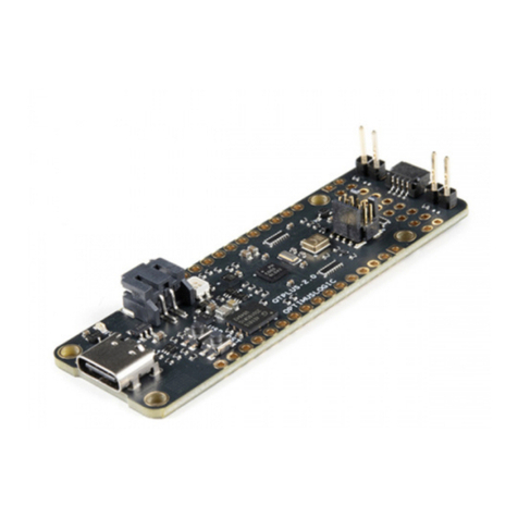
sparkfun
sparkfun QuickLogic Thing Plus HOOK-UP GUIDE
Texas Instruments
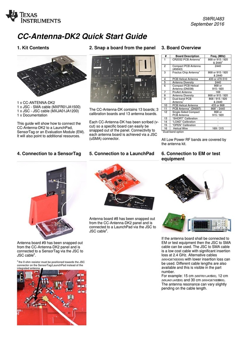
Texas Instruments CC-Antenna-DK2 quick start guide
