Secotech ST-031M Piranha User manual
ST-031M Piranha
Multi-purpose Search Device
USER MANUAL

TABLE OF CONTENTS
1. INTRODUCTION ...................................................................................................................................................................... 2
2. GENERAL CHARACTERISTICS OF THE DEVICE ........................................................................................................................3
2.1. PURPOSE AND MAIN FEATURES ..............................................................................................................................3
2.2. PACKING AND DELIVERY SET ...................................................................................................................................4
2.2.1. Packing ...................................................................................................................................................... 4
2.2.2. Delivery set ................................................................................................................................................5
2.3. DESIGN OF THE MAIN CONTROL, PROCESSING AND DISPLAY UNIT.........................................................................6
3. ST-031M OPERATION MODES................................................................................................................................................ 7
3.1. SWITCHING ON ST-031M.......................................................................................................................................... 7
3.2. MODE "CHANNEL SELECTION" .................................................................................................................................7
3.2.1. "Settings" mode..........................................................................................................................................8
3.3. "CHANNEL 1" MODE ...............................................................................................................................................9
3.3.1. "Panorama" mode ..................................................................................................................................... 9
3.3.2. "Differential" mode ...................................................................................................................................10
3.3.3. "Fixed Frequency" mode ............................................................................................................................11
3.3.4. "SEARCH" Mode .........................................................................................................................................12
3.3.5. "Analysis" mode ........................................................................................................................................ 13
3.3.6. "Wireless communications" mode .............................................................................................................14
3.3.7. Recommendations for the use ST-031M in selective RF detector mode ("Channel 1") .............................16
3.3.7.1. Search using automated signal detection mode ..................................................................................17
3.3.7.2. Search in manual mode ....................................................................................................................18
3.3.7.3. Search in “Wireless Networks” mode ................................................................................................ 20
3.4. "CHANNEL 2" MODE. SCANNING RECEIVER ............................................................................................................23
3.4.1. "Panorama" mode ..................................................................................................................................... 23
3.4.2. "Differential" mode ....................................................................................................................................24
3.4.3. "Fixed Frequency" mode ............................................................................................................................25
3.4.4. "SEARCH" mode..........................................................................................................................................26
3.4.5. "Analysis" mode ........................................................................................................................................ 27
3.4.6. Recommendations for the use of ST-031M in scanning receiver (Channel 2) mode ................................. 28
3.4.6.1. Search using automated signal detection mode ..................................................................................30
3.4.6.2. Search using manual signal detection mode .......................................................................................32
3.5. "CHANNEL 3" MODE. LOW-FREQUENCY AMPLIFIER ...............................................................................................34
3.5.1. Mode enabling/disabling ...........................................................................................................................34
3.5.2. Selecting the type of the adapter .............................................................................................................. 34
3.5.3. Sub-mode “Oscilloscope” ........................................................................................................................... 34
3.5.4. Sub-mode “Linear spectrum” .....................................................................................................................35
3.5.5. Sub-mode “Octave spectrum” ....................................................................................................................35
3.5.6. Recommendations for the use of ST-031M in “Channel 3”-Low-frequency amplifier ................................36
3.5.7. Multipurpose adapter for checking wire lines (BWLC031M) in the mode Low- frequency amplifier ........36
3.5.8.1. Conductive wire lines differential generator .......................................................................................37
3.5.8.2. Induction converter (Magnetic field sensor) .......................................................................................38
3.5.8.3. Ultrahigh frequency sensor (UWBD031M) .........................................................................................39
4. OPERATING ST-031M WITH A PERSONAL COMPUTER ........................................................................................................ 40
4.1. THE PROGRAM ST031M-PIRANHA .......................................................................................................................... 40
4.2. “CHANNEL 1” MODE ................................................................................................................................................41
4.2.1. “Search” mode ...........................................................................................................................................42
4.2.2. “Wireless Networks” mode ........................................................................................................................42
4.2.2.1. Mobile devices ................................................................................................................................ 43
4.2.2.2. Base stations ................................................................................................................................... 43
4.2.2.3. User list...........................................................................................................................................43
4.2.3. “Fixed frequency” mode ............................................................................................................................44
4.2.4. “Oscilloscope” mode ..................................................................................................................................45
4.3. “CHANNEL 2” MODE ................................................................................................................................................46
4.3.1. “Search” mode ...........................................................................................................................................46

4.4. “CHANNEL 3” MODE ................................................................................................................................................47
4.4.1. “Settings” menu ......................................................................................................................................... 48
4.4.2. “Help” menu ..............................................................................................................................................48
5. TEST SOUND EMITTING DEVICE ............................................................................................................................................50
6. ST-031M POWER SUPPLY ......................................................................................................................................................51
7. TECHNICAL CHARACTERISTICS OF ST-031M .........................................................................................................................52

1. Introduction
ST-031M is a new generation multifunction counter surveillance device for detection and localization Special
Technical Means of Obtaining Secret Information (STMOSI) and for solving other information protection tasks
related to information protection technical measures effectiveness evaluation. ST031M is logic continuation of
the well-known multipurpose devices series „Piranha".
All features of previous models are incorporated into ST-031M:
ST-031M construction, delivery set, technical features and characteristics allow detection of wide range of
mostly dangerous STMOSI devices.
Technical possibilities of the device as whole and additional devices allow finding almost all of the most
dangerous physical fields used by STMOSI.
Independence from external power supplies allow autonomous operation and removes limitation of
device use.
Connection to PC allows controlling and information logging directly from computer screen.
ST-031M main differences from previous models ST-031 and ST-031P:
Selective wide band detector of electromagnetic field detector with adjustable bandwidth from 1 to 40
MHz is used for detection of STMOSI.
Selective HF detector bandwidth is wider than in previous models and is from 140 to 4420 MHz.
Wider band of wire lines scanning receiver 0,05-140 MHz.
ST-031M uses colour graphics display which increases informativeness of displayed information.
ST-031M user interface is intuitively understandable.
ST-031M comes in waterproof case, made of impact resistant plastic. Compact and comfortable styling
ensures safety of the device and its components during storage and transportation.

3 | P a g e
2. General characteristics of the device
2.1. Purpose and main features
Multifunctional searching device ST-031M is designed for the detection and localization of technical surveillance
measures and to identify the natural channels of information leakage, as well as for quality control of data
protection.
ST-031M maintains performance standards and compliance with the parameters of the technical conditions when
the supply voltage is not lower than 4.8V, the atmospheric pressure from 630 to 820 mm Hg, ambient
temperature of -5 to +350 ° C and humidity not exceeding 95%.
ST-031M allows us to perform following search tasks:
Discovery of the facts and determining the location of the radio-emitting devices, which creates a potentially
dangerous information leakage radiation. These means primarily include the following:
Radio microphones;
Telephone transmitters;
Radio-stethoscopes;
Concealed video cameras equipped with a radio channel for transmission of information;
Technical means or systems for spatial radio frequency radiation;
Beacons of the systems used for moving objects monitoring (e.g. people, transportation means, goods
etc.);
Unauthorized radio stations, radio handsets, and also telephones with radio-extension;
Radio modems and digital wireless access systems.
Identification of digital protocols used in the detected radio signals. Device is able to distinguish between signals
from the base station and signals from cellular phones.
Detection and localization of STM means which use conductive lines of various intended application, for
transmission of information, as well as the technical means of information processing, creating informative
crosstalk signals on the cable wires. Such means may include:
Devices transmitting intercepted information by AC 220V mains lines and capable of operating at
frequencies up to 30 MHz;
Technical means of imposing a linear high-frequency signals operating at frequencies above 150 kHz;
Devices transmitting intercepted information by subscriber telephone lines, the lines of fire and burglar
alarm systems with a carrier frequency above 20 kHz
Computers and other technical means of production, reproduction and transmission of information.

4 | P a g e
2.2. Packing and delivery set
Device ST-031M set is subject-oriented solution to the above search
tasks, to ensure versatility and autonomy of the work, as well as to
provide convenience and reliability of transportation and storage.
2.2.1. Packing
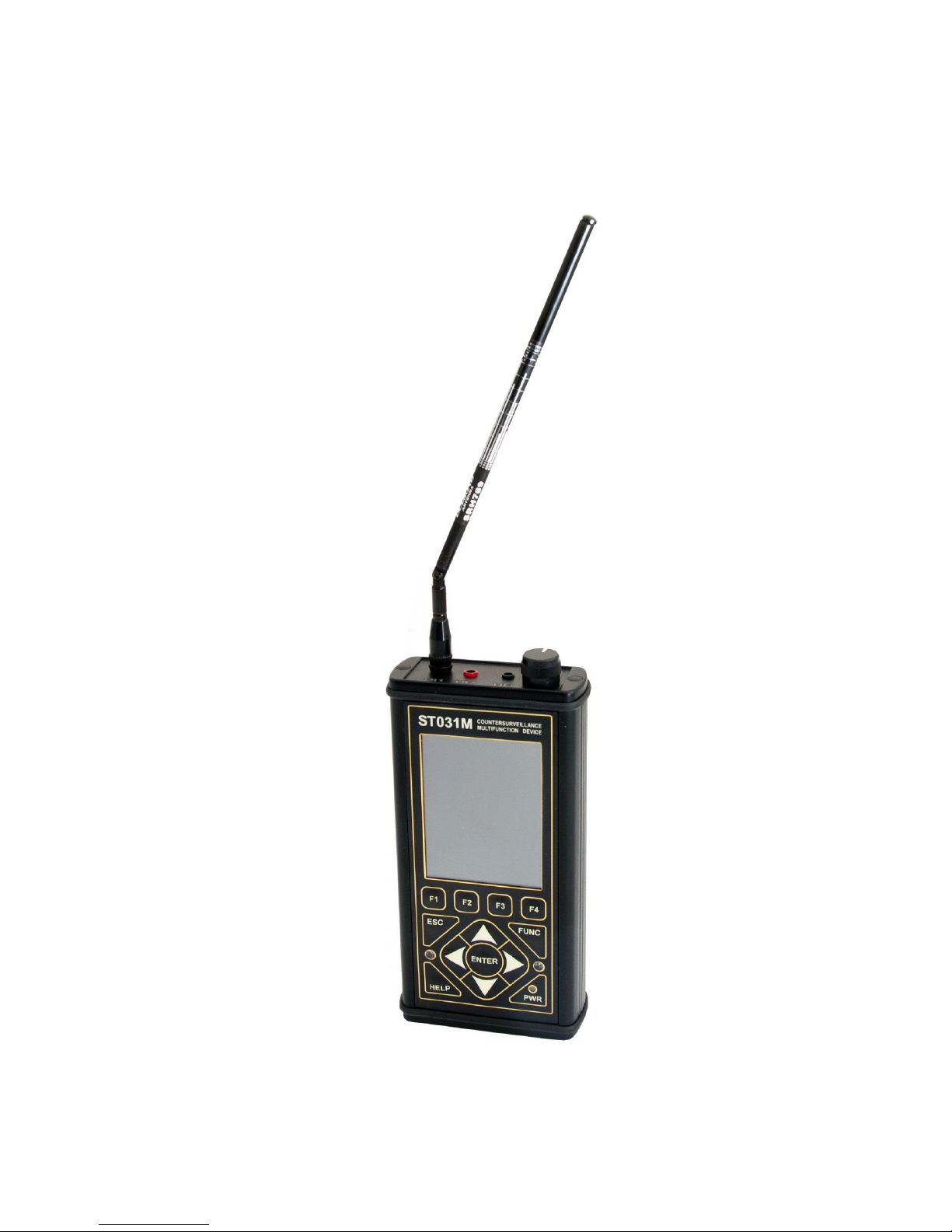
The device is made in a portable version. High-impact, waterproof
plastic carrying case NANUK-915 (Fig. 1) is used for transportation
and storage of the device. External dimensions of the case are
presented in Figure 2.
Safety during transportation and storage, as well as the convenience
of working with the device is provided by the original laying, which
consists of two parts: the upper (extracted from the case) and lower
(non-removable).
Layout of ST-031M accessories is presented in Figure 3.
Each component, supplied with ST-031M, has its own individual place.
To avoid mechanical damage, the device and its components must be
placed in accordance with the standard laying scheme.
Figure 1
Figure 2
Figure 3
5 | P a g e
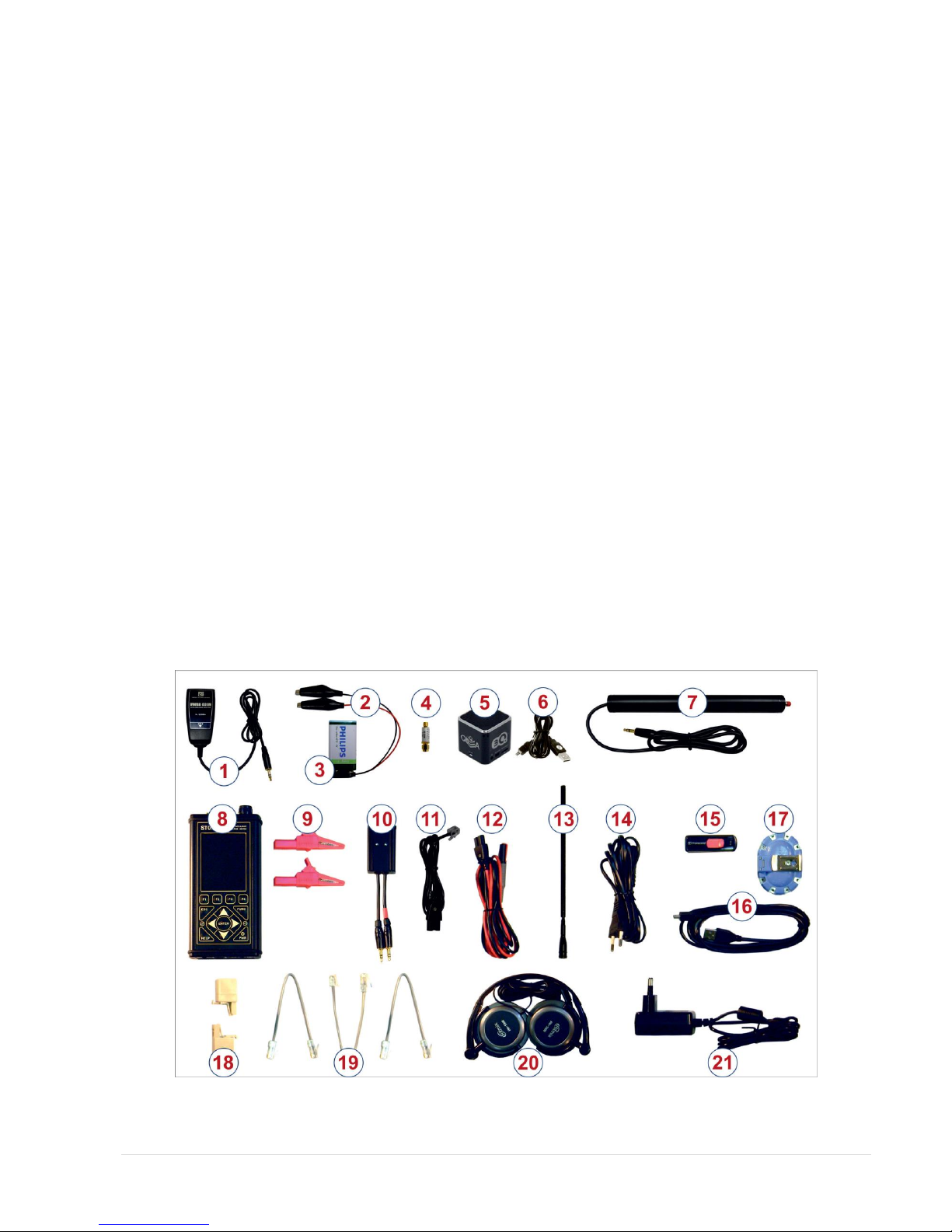
2.2.2. Delivery set
ST-031M delivery set includes:
1. Ultrahigh frequency sensor (UWBD031M).
2. Conductive wire lines differential generator
3. Battery (for conductive wire lines differential generator) .
4. Attenuator.
5. Test sound emitting device.
6. Connecting cable of sound emitting device.
7. Induction converter (Magnetic field sensor).
8. Main controlling, processing and displaying unit.
9. "Crocodile" type clamps (2 pcs).
10. Multipurpose adapter for checking wire lines - BWLC031M.
11. Cable to connect BWLC031M adapter to telephone lines.
12. Multipurpose cable to connect BWLC031M adapter to wire lines.
13. High-frequency telescopic antenna.
14. Cable to connect BWLC031M adapter to electricity sockets for scanning receiver CH2.
15. Flash drive with software.
16. Cable to connect to a PC.
17. Adapter to connect BWLC031M adapter to the multi-wire cables.
18. Telephone adapters (2 pieces).
19. Cable connectors type RG45: 8х4; 8х6; 8х8.
20. Headphones.
21. Charger.
22. Carrying case.
23. User manual and warranty certificate.
Figure 4 shows the main components of ST-031M (numbering corresponds to the numbering of the figure 3).
Figure 4
6 | P a g e
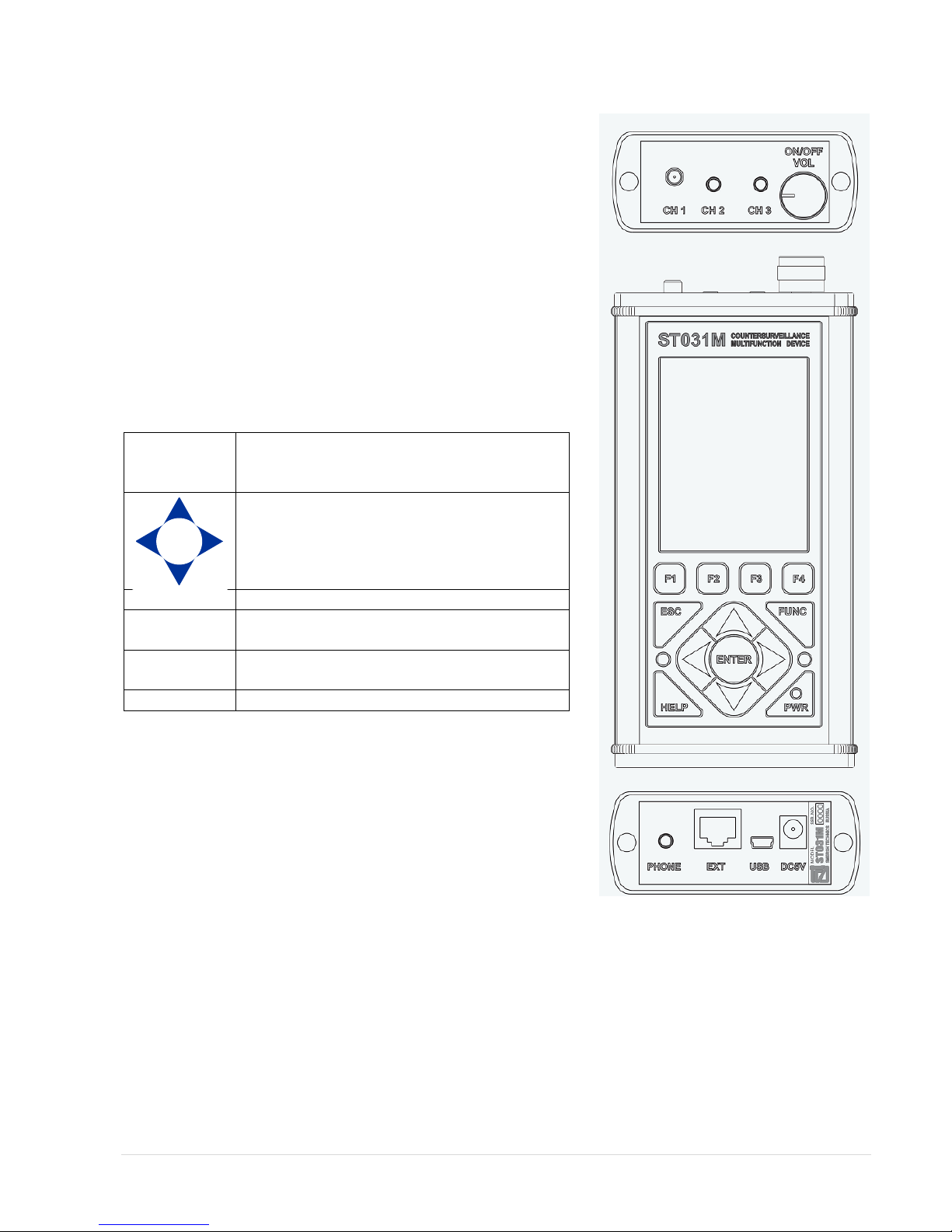
2.3. Design of the main control, processing and display unit
The main unit is the main part of ST-031M. Figure 5 shows the
appearance of the front, top and bottom panels of the main unit.
At the top of the main unit are:
RF connector for antenna «CH 1"
jack for connecting scanning receiver adapter «CH 2"
jack for connecting sensors and adapters «CH 3"
handle power on / off and volume control «ON / OFF VOL»
The front of the main unit includes:
a. color graphic LCD display (320x240 pixels)
b. power indicator «PWR»
c. two windows of infrared transmitters for wireless
headphones;
d. 12 keys membrane keyboard.
Keys assignment:
F1 F2
F3 F4
Group function buttons. Their function varies
depending on the mode ST-031M and indicated
on the display directly above the button.
Buttons to change settings.
ENTER
Confirm the selected option button / mode.
ESC
Button to return to the previous mode, or
cancel the command.
FUNC
Additional functional button. Provides access to
additional features.
HELP
Contexts tips.
More detail button assignments will be presented in the description
of controls and indicators in Section 2.
Bottom panel has:
Headphone jack «PHONE»
Digital port for connection of external digital devices «EXT»
Socket for connecting to a PC «USB»
Socket to connect power supply / charger «DC5V»
In a bottom panel you can find a shield with serial number and
manufacturer name indicated.
Figure 5

7 | P a g e
3. ST-031M operation modes
Systemotechnical and software foundation, incorporated in the design and operation of the device algorithms
make it possible to apply it in the following modes:
selective high-frequency electromagnetic field detector (in the frequency range 140-4420 Mhz);
Scanning Analyser for wire lines (in the frequency range of 0.05-140 MHz);
Low-frequency signal amplifier (in the frequency range 0.02-100 kHz).
When connecting one or another external device, you must manually choose appropriate mode of operation.
3.1. Switching on ST-031M
Switching the device On/Off is made by rotating volume knob «ON / OFF VOL», located on the top panel (Fig. 5).
To access the "Select Channel" mode, press any button on a ST-031M keyboard.
3.2. Mode "Channel selection"
"Channel selection" is primary menu where user can
chose operating mode or set the system configuration.
The screen in the "Channel selection" is shown in
Figure 7.
The numbers indicated in the figure:
1. system information text
2. the name of the current mode
3. Battery charge indicator
4. time display (hh: mm)
5. menu “Chose mode”
6. the menu item "Channel 1"
7. the menu item "Channel 2"
8. the menu item "Channel 3"
9. the menu item "Settings"
10. currently selected menu item
11. function keys assignment
12. function name assigned to button F1
13. function name assigned to button F2
14. function name assigned to button F3
15. function name assigned to button F4
Figure 6
Figure 7
SELECT CHANNEL 00:00
Channel1 Channel 2 Channel 3
1
2 3 4
5
6
7
8
Setting
9
10
11
12 13 14 15
Channel Hz 1 (140...4 4 2 0 М )
Channel Hz 3 (0,0 2 ...100К )
Setting
Channel Hz 2 (0,0 5 ...30М )
Figure 7
8 | P a g e
Available functions
Key
Menu item selection
Activating selected mode
ENTER
Available modes
"Channel 1" high frequency selective detector
(140- 4200 MHz)
F1 or menu button pos.6 Fig.7
"Channel 2" scanning receiver (0.05 ... 30 MHz)
F2 or menu button pos. 7 Fig.7
"Channel 3" low frequency amplifier
F3 or menu button pos. 8 Fig.7
"Settings" (time, date, language, infrared headset)
F4 or menu button pos. 9 Fig.7
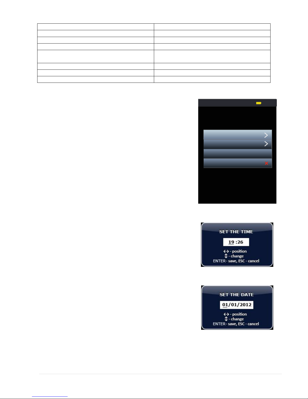
3.2.1. "Settings" mode
In the "Settings" menu user can set following system parameters:
Time
Date
Language menu
Enable / disable the IR headset.
Setting system time
Press button F4 or chose appropriate menu item in the "Channel
Selection" mode.
To adjust the time select menu item in the box that says „Time“ and
presses ENTER.
In the window that appears, chose between hours or minutes (Fig. 9)
using the buttons LEFT or RIGHT. Use buttons UP or DOWN to set the
desired value. Confirm set time by pressing button ENTER.
If you press the ESC button, the unit exit without saving your changes.
New settings will be stored in memory even when power is turned
off.
Setting system date
To adjust the time select menu item in the box which says "Date" and
press ENTER.
In the window that appears, set the required parameters (similar to
how setting time)
Confirm set values by pressing ENTER. Tto return to the Mode menu
"Settings" press button ESC.
Figure 8
Figure 9
Figure 10
SETTINGS 00:00
Date
Язы к/ Language ENG
IR-headset
Time
9 | P a g e
Selecting the Interface Language
The device has English and Russian language interface (the default is Russian).
To change language select menu item "Язык / Language”(Fig. 8) and press ENTER. In this menu, chose “RUS” or
“EN”.
Activating IR headphones
In addition to wired headphones, the instrument provides possibility to use wireless IR headphones. By default,
the IR transmitter is off. In order to turn them on in the mode menu "Settings" chose "IR Headset" and press
ENTER. Choose between IR mode by pressing ENTER button: - IR transmitter is disconnected or - IR
transmitter is active. Press ESC to return to previous mode.
3.3. "CHANNEL 1" mode
Selective HF Detector
In this mode user can detect and identify radio signals in the frequency
range from 140 to 4420 MHz, as well as to localize the sources of such
signals, located in the inspected areas.
3.3.1. "Panorama" mode
This mode is the base for selective RF detector. Mode is activated in
"Channel selection" menu by pressing the F1 key or by selecting the
menu item "Channel 1".
The screen is shown in Fig. 11.
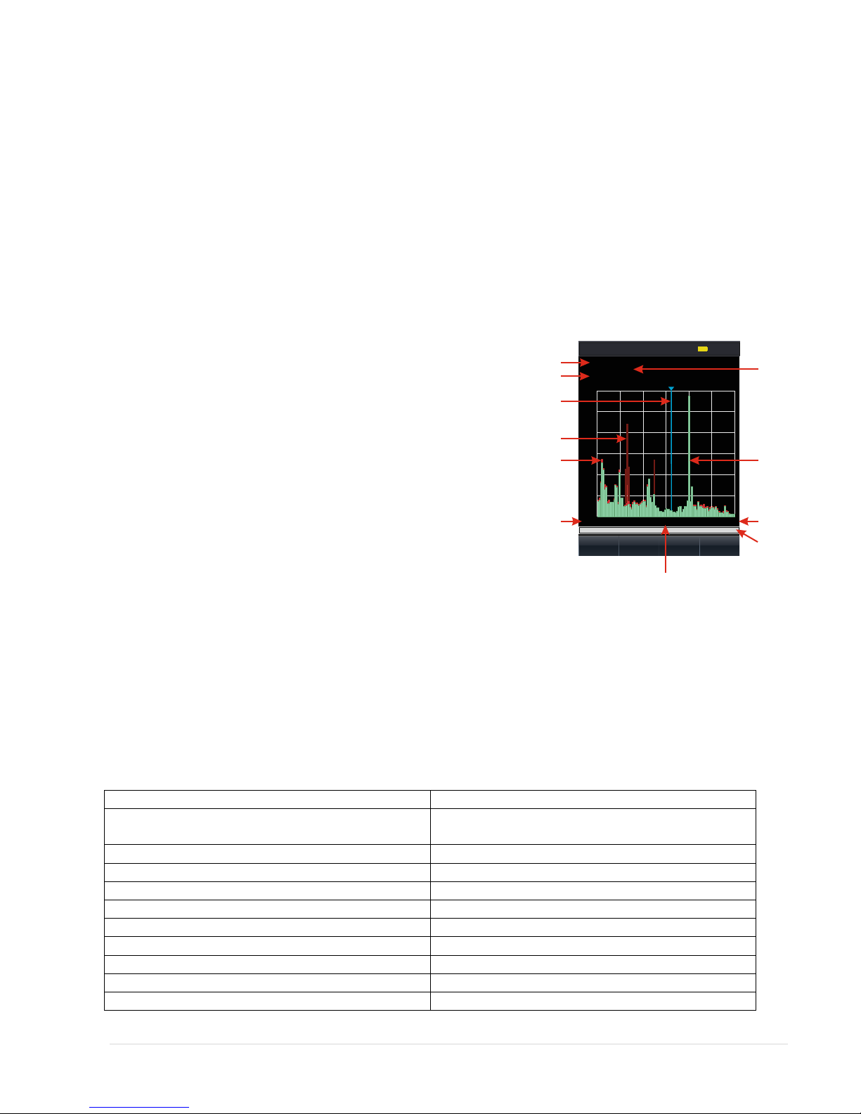
The numbers indicated in the figure:
1. value of lower and upper bounds of the range panorama
2. value of scan step Figure 11
3. frequency corresponding to the position of the marker on display
4. screen marker
5. max. signal level at a given frequency for the time of the session (maroon colour)
6. pulse component of the signal (red colour)
7. constant component of the signal (green colour)
8. value of the lower boundary frequency of the panorama
9. value of the upper boundary frequency of the panorama
10. value of the center frequency of the panorama
11. indicator showing current viewing band in comparison to maximum possible.
Available functions
Key
Changing the scanning step and limits the range of
frequencies: 1, 2, 5, 10, 20, 40 MHz
UP or DOWN
Move display marker
LEFT or RIGHT
Show context tips
HELP
Available modes
"Differential mode"
F1
"SEARCH"
F2
"Wireless networks"
F3
"Fixed frequency"
F4
Exit from current mode
To “Chose channel” mode
ESC
CHANNEL 1 00:00
FIND
Diff
mode
.Wireless
Comm. Fix
Freq.
.
Range: 140-4420M Hz
Step: 40MHz
Marker: 2460MHz
140MHz 2270MHz 4420MHz
10
20
30
40
50
dB
12
3
4
5
67
8 9
10
11

10 | P a g e
3.3.2. "Differential" mode
In this mode, the signal levels, obtained in the "Panorama," taken as
"zero" and displays only the exceeding set signal level. Enabling - the
F1 key from the "Panorama" mode.
Indication of switch-on - change the colour labels "Diff. mode" from
yellow to orange and lightening the background colour of the label
(item 4 in Fig. 12)
The screen of the differential mode is shown in Figure 12.
Numbers indicated in the figure:
1. maximum signal level for the entire session observation for
a given frequency (maroon colour)
2. indication of pulse signals (yellow colour)
3. indication of the average signal level (purple colour)
4. Indicates if differential mode is active.
Figure 12
Available functions
Key
Changing the scanning step and limits the range of
frequencies: 1, 2, 5, 10, 20, 40 MHz
UP or DOWN
Move display marker
LEFT or RIGHT
Show context tips
HELP
Available modes
"Panorama mode"
F1
"SEARCH"
F2
"Wireless networks"
F3
"Fixed frequency"
F4
Exit from current mode
To “Chose channel” mode
ESC
To “Panorama” mode
F1
CHANNEL 1: 00:00
FIND Wireless
Comm. Fix
Freq.
.
Range: 140-4420MHz
Step: 40MHz
Marker: 2460MHz
140MHz 2270MHz 4420MHz
10
20
30
40
50
dB
Diff
mode
.
1
2
3
4

11 | P a g e
3.3.3. "Fixed Frequency" mode
This mode is designed for fine-tuning to the frequency of the detected
signal frequency, as well as to locate the source.
Mode activation is done from the "Panorama" mode by pressing button
F4
Mode screen shown in Figure 13.
The numbers indicated in the figure:
1. the value of center frequency of the signal (corresponding to the
frequency which was set in "Panorama" or "Diff. Mode" modes);
2. the value of bandwidth (corresponding to the value set in
"Panorama" or "Diff. Mode" modes);
3. max. signal level for the entire observation session
4. an indicator of relative changes in signal level (shown in red pulse
component)
5. an indicator of relative changes in signal level (shown in green DC
component).
Figure 13
Available functions
Key
Monitoring changes in the relative signal level of the
indicator (item 4, 5, Figure 13)
Listening to the demodulated signal on speaker or
headphones
Adjust the center frequency of the signal with a step
equal to the bandwidth (Figure 13 item 1)
LEFT or RIGHT
Changing the bandwidth: 1, 2, 5, 10, 20, 40 MHz (Fig. 13
key 2)
UP or DOWN
"Zeroing" the relative signal level, "Const. zero "
F1
Show context tips
HELP
Available modes
“Oscilloscope”
F2
Return to “Panorama” or “Diff. Mode” mode
ESC
"Oscilloscope" Sub-mode
Screen sub modes "Oscilloscope" is presented in Figure 14.
The numbers indicated in the figure:
1. value of dividing the time axis (ms or msec)
2. value of the amplitude axis (dB)
3. measured value of signal amplitude (dB)
Available functions
Key
Acoustic control of demodulated
signal
Visual inspection of demodulated
signal waveform
Changing the scale interval of the
time axis: 100, 200, 400, 800 μs /
div, 1, 3, 6 ms / div
LEFT or RIGHT
Scale change of fission axis
amplitude: 2.5 or 12,5 dB / div
UP or DOWN
Call of contexts tips
HELP
Exit to previous mode
ESC
CHANNEL FIX1: . 00:00
Set “0" OSC
Fr e q : .0 M Hz
B a n dw id th : 1 M H z
391
12
3
4
5
Figure 14

12 | P a g e
3.3.4. "SEARCH" Mode
Automatic detection of signal levels that exceed an adaptive threshold.
The search is performed in frequency range defined in the "Panorama"
or "Diff. regime." modes.
When you activate this mode (press F2 in "Panorama" mode) message is
briefly displayed on screen accompanying the process of signal detection
(Fig. 15).
Upon completion of the search process, forming a table presented in
Figure 16, where the numbers denote:
1. total number of detected signals
2. number of detected signal in table
3. central frequency of detected signal
4. relative level of detected signal
5. additional information about the signal
6. position indicator line
7. indicator of changes in the relative level of the selected signal
(shown in green DC component)
8. indicator of changes in the relative level of the selected signal
(red shows the DC component).
If you find air television signals, digital communication base stations and some other standard signals, the
additional information (item 5 Figure 16) specifies the type of data signals, the color of the labels in a row - the
green, which corresponds to the status of "known" (not dangerous) signal.
Upon detection of signals of digital mobile communications in the additional information (item 5 Figure 16)
specifies the type of data signals, the colour of text boxes in a row - red, which corresponds to the status of
"dangerous" (potentially dangerous) signal.
Upon detection of signals of a type that cannot be identified automatically, the additional information (item 5
Figure 16) indicates «unknown», while the colour labels in a row - white, which corresponds to the status of
"unknown" signal.
At its discretion, the user can change the status of the signals detected by manually.
Available functions
Key
The choice of the signal in the list. Selected signal is
displayed as a highlighted line
UP or DOWN
Listening to the selected demodulated signal on the
speaker or headphones.
Monitoring changes in the relative signal level of the
indicator (item 7, 8, Fig. 16)
Removing the signal from the list
F1
Assignment of signal status. The options are:
Press F2
"Dangerous" - red label
"Known" - green label
"Unknown" - white label
Call of contexts tips
HELP
Available modes
"Analysis"
F3
Output mode "Panorama" without saving results
ESC
Figure 16
Figure 15
13 | P a g e
3.3.5. "Analysis" mode
In general, the work unit in the "Analysis" mode is similar to working in
the "Fixed-frequency" mode (p.3.3.3), except that in this case there is a
possibility to save changes.
Mode screen "Analysis" presented at Fig.17.
The numbers indicated in the figure:
1. value of the center frequency of the selected signal;
2. the value of fixed bandwidth;
3. max. value of the signal level at a given frequency for the entire
session of observation;
4. an indicator of changes in the relative level of the selected signal
(shown in red pulse component);
5. an indicator of changes in the relative level of the selected signal
(shown in green DC component).
Figure 17
Available functions
Key
Control of the relative signal level according to the indicator (item 3, 4, Figure 17)
Listening to the demodulated signal on speaker or headphones
Adjust the center frequency with a step equal to the bandwidth
LEFT or RIGHT
Changing the bandwidth: 1, 2, 5, 10, 20, 40 MHz
UP or DOWN
"Zeroing" the relative level of the selected signal, "Setting zero"
F1
Save the changed value of the frequency of returning to the table of detected signals
F3
Call of contexts tips
HELP
Available modes
"Oscilloscope"
F2
Exit from current mode:
to the table of detected signals without saving the changed value of the center
frequency of the signal
F4 or ESC
to the table of detected signals while preserving the values of the modified center
frequency of the signal
F3
"Oscilloscope" Submode
Screen "Oscilloscope" submode is presented in Figure 18.
The numbers indicated in the figure:
1. value of dividing the time axis (ms or msec)
2. value of amplitude axis scale (dB)
3. measured value of the signal amplitude (dB)
Available functions
Key
Acoustic control of demodulated signal
Visual inspection of demodulated signal waveform
Changing the scale interval of the time axis: 100,
200, 400, 800 μs / div, 1, 3, 6 ms / div
LEFT or RIGHT
Scale change of fission axis amplitude: 2.5 or 12,5 dB
/ div
UP or DOWN
Call of contexts tips
HELP
Exit to previous mode
ESC
Figure 18
CHANNEL Analysis1: 00:00
Set “0" OSC Save
changes
Fr e q : 1 91 .0 M Hz
B a n dw id th : 1 M Hz
Back to
list
12
3
4
5

14 | P a g e
3.3.6. "Wireless communications" mode
This mode is designed for search of digital transmitters using the most common standard data transfer protocols,
as well as a qualitative assessment levels of base stations of digital communication.
In this mode, there are three main sub-mode search digital devices:
- "Mobile devices"
- "Base stations"
- "User list"
To enter the "Wireless communications" from the "Panorama" mode press button F3, which automatically
connects sub-mode "Mobile devices".
Sub-mode "Mobile devices"
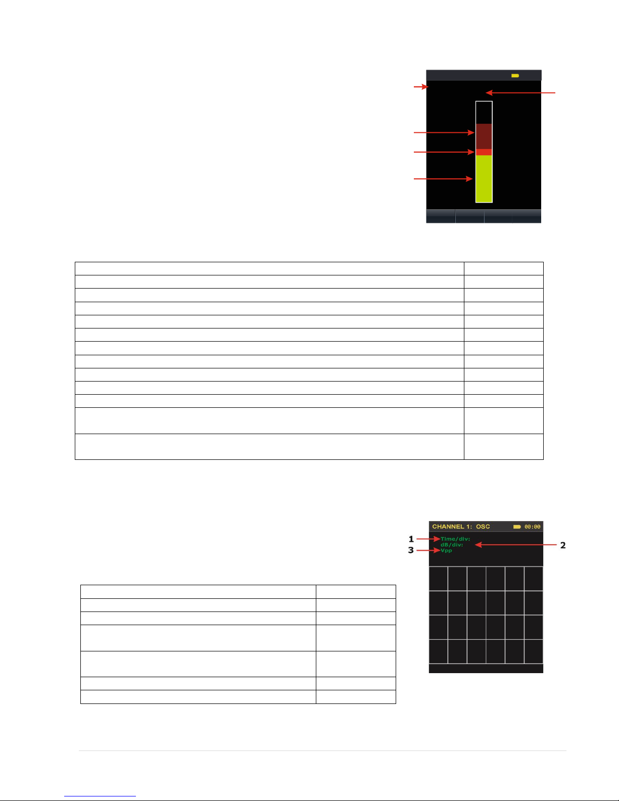
The view of the screen is presented on figure 19.
The numbers indicated in the figure:
1. Name of a standard digital signal
2. Indicator of the relative signal level.
3. Table cursor.
Available functions
Key
Selecting the standard
UP or DOWN
Evaluation of the relative levels of signals
selected in wireless standards
Switching selected standard off / on
F2
Simultaneously switching on all previously
Switched off standards
F3
Call of contexts tips
HELP
Available modes
“Base stations”
F1
“Analysis”
F4
Exit to previous mode
ESC
Sub-mode "Base stations"
The view of the screen is presented on figure 20.
Available functions
Key
Selecting the standard
UP or DOWN
Evaluation of the relative levels of signals
selected in wireless standards
Switching selected standard off / on
F2
Simultaneously switching on all previously
Switched off standards
F3
Call of contexts tips
HELP
Available modes
“User list”
F1
“Analysis”
F4
Exit to “Panorama” mode
ESC
Figure 19
Figure 20

15 | P a g e
Sub-mode "User list"
This sub-mode allows operator to create his own list of bands with particular frequency range of standard digital
protocols. For example, an alternative Wi-Fi, with 3.6 GHz working range. Furthermore, this mode allows to
create a set of "dangerous" frequency bands, which are commonly used in wireless microphones, video cameras
with a radio channel and other radio transmitting STMOSI. Creation of User list is performed by using the PC
software.
The view of the screen is presented on Figure 20a.
Available functions
Key
Selecting the standard
UP or DOWN
Evaluation of the relative levels of signals
selected in wireless standards
Switching selected standard off / on
F2
Simultaneously switching on all previously
Switched off standards
F3
Call of contexts tips
HELP
Available modes
“Base stations”
F1
“Analysis”
F4
Exit to “Panorama” mode
ESC
Figure 20a
Sub-mode "Analysis"
This sub-mode is designed for selecting the frequency of the detected signal, and also to find the location of the
signal source. To enter from the sub-modes "Mobile devices", "Base stations" and "User list " press button F4.
The view of the screen is presented on Figure 20b.
The number meaning in the illustration:
1 - The value of the center frequency band;
2 - Set bandwidth value;
3 - The maximum signal level for the entire session of observation.
4 - An indicator of the relative change in the signal level
(Pulsing component shown in red);
5 - An indicator of the relative change in the signal level
(Continuous component shown in green);
6 - The value of the lower boundary of the set bandwidth;
7 - The value of the upper boundary of the set bandwidth;
8 - An indicator showing the viewing width and span relatively to
the established boundaries of the bandwidth.
Figure 20b
Available functions
Control of changes in the relative signal level
on the indicator.
Listen to the demodulated signal to a
speaker or headphones

16 | P a g e
3.3.7. Recommendations for the use ST-031M in selective RF detector mode ("Channel 1")
Using ST-031M in different modes of selective HF detector is focused on the detection, identification and
localization of special technical means of obtaining secret information (STMOSI), transmitting the signal off-site
search in the frequency range 140-4200 MHz. It should be understood that the device can detect only "active"
STMOSI, e.g. working at the time of transfer.
Unique features implemented in ST-031M selective detector are:
The ability to detect signals exceeding the threshold in an adaptive automatic mode with the formation of
a list of these signals. The list indicates the most important information about the signal (center
frequency, level, information on the possible type of signal). In addition, if the frequency of the detected
signal coincides with the frequencies of known signals (broadcast stations, base stations, communications
systems, etc.), it is automatically assigned the status of "known", ie certainly not "dangerous". When a
match is the central frequency of the detected signal with frequencies typical for mobile digital
communications, such signals automatically is assigned the status of "dangerous" because it can be
signals of wireless microphones that use the channel same as a standard digital protocols.
The presence of differential treatment makes it possible-selected signals, the sources are located in the
near zone, e.g. on-site search.
Ability to control signal at a fixed frequency (modes' Fix. Frequency "and" Analysis "). This greatly
simplifies the process of localizing the source of the signal, even against the more powerful signals.
Ability to listen to the acoustic information on the built-in speaker or headphones allows operator to
identify the signals. If you set the center frequency of coincidence with the frequency of wireless
microphone located in the premises (with not encoded transmission), the headphones will hear the noise
of the room. To identify the source of the detected signal is recommended that you create in a room
called "Control the sound." The source of this sound can serve as a tape recorder, CD / DVD player or a
specific source of the reference tone. Should not be used for this purpose the television or radio.
Should be considered as dangerous signals:
-demodulated signals are correlated with the signal source reference tone (this is typical for analog
microphone with "unencrypted transmission channel and a relatively simple types of encoding);
-frequencies do not coincide with the frequencies of TV channels, radio and other "known" sources;
-levels of which vary considerably when entering and navigating through the object being tested (with high
probability the sources of these signals are close to the device).
In accordance with the characteristics of the selective RF detector, in general, there are three main options for
transmitting STMOSI search:
-Search using the automatic mode;
-Search in manual mode;
-Search for digital mobile communications and STMOSI, based on them.
The proposed further uses of ST-031M are typical and may be adjusted depending on the characteristics of the
object and the challenges faced by search operators.

17 | P a g e
3.3.7.1. Search using automated signal detection mode.
This search option is essential. Its main advantages - simplicity and minimal detection time. Recommended for
use on most sites, provided the low and medium levels of radio spectrum load.
No.
Action
Control element
Indication
Preparation
1.
Inside of the scanned
area connect the RF
antenna to the "CH1"
and headphones to the
«PHONE» at the bottom
of the unit
2.
Switch-on the device
Turn the volume control
clockwise.
Splash screen. Figure 6.
3.
Enter into the "Channel
Selection" mode
Press any key on the keyboard
Screen "Channel selection" mode.
Figure 7.
4.
Enter into the "Settings"
mode (if required to
change settings)
Two ways:
- With the buttons UP or DOWN
set the cursor to the "Settings"
and press ENTER;
- Press the F4 button
Screen "Settings" mode. Figure 8.
5.
Perform the necessary
settings change and exit
the into the "Channel
selection" mode
In accordance with Clause 3.2.1.
6.
Enter into the "Channel
1" mode
Two ways:
- With the buttons UP or DOWN
set the cursor to the
"Channel 1" and press ENTER;
- Press F1 button
Basic mode selective RF Detector
"Panorama" Figure 11.
Signal detection
7.
Enable automatic
search mode
F2 button
The message as in Fig.15 will be shown
on screen.
Upon completion of the automatic
search, results will be generated and
presented on-screen table (list) of
detected signals, arranged in ascending
order of their center frequency.
By default, cursor is located on the first
row of the table. Fig.16.
8.
Select signal
Use UP or DOWN
set table pointer to a string
containing information about
the signal of interest.
In headphones listen to demodulated
signal. The indicator (position 7, 8,
Fig.16) shows the relative level of
constant and pulsed signal components
9.
Select mode “Analysis”
Button F3
Screen "Analysis." mode Figure 17.
In headphones listen for demodulated
signal.
The display shows the relative level of
constant and pulsed signal components
10.
Adjust the center
frequency and
bandwidth signal.
adjustment:
frequency - LEFT or RIGHT
bandwidth - UP or DOWN
By observing changes in the relative
level of the signal and listening to the
demodulated signal, set the frequency
and the bandwidth corresponding to

18 | P a g e
the maximum signal level and the best
signal quality in the headphones
11.
Exit from the "Analysis"
to the table of detected
signals
Save changes - F3 button
Without saving changes -
Button F4 or ESC
When you press F3, detected signal
parameters in the table will change in
accordance with the adjustments.
12.
Changing status of the
signal
Successive pressing F2
Font color changes
13.
Remove signal from list
Use UP or DOWN to set the
table cursor on the signal you
want to delete. Press the F1
button
The line will be removed from the list of
detected signals.
Signal source localization
14.
Chose signal
Same as in step 8
15.
Switch-on “Analysis”
mode
Same as in step 9
16.
Setting current signal
level as “Zero”
Button F1
The relative level of the signal is taken
as "zero", while the level of the
indicator will be significantly reduced.
17.
Locate place of signal
source
By observing changes in the relative
level of the indicator, find place where
indicator shows maximum level.
Repeat steps 14-17 for all "dangerous" and "unknown" signals in the table.
Notes:
If the list of detected signals contains signals whose frequency is within the 140-280 MHz range, it might be that
these signals are the upper harmonics of high-power signals, with central frequencies below 140 MHz. This
circumstance is due to the fact that the lower limit of the working range of the selective RF detector is 140 MHz
and the device cannot record the signal at frequencies below this limit. However, their harmonics are detected
reliably within the operating range.
3.3.7.2. Search in manual mode
This option is recommended to apply in a complex electromagnetic environment. The advantages of this method
include the possibility of using selective RF detector in a differential mode, which allows distinguishing between
external and internal signals (sources which are located in the near zone). However, the search takes longer than
in the automatic mode.
No.
Action
Control element
Indication
Preparation
1.
Outside of the scanned
area connect the RF
antenna to the "CH1"
and headphones to the
«PHONE» at the bottom
of the unit
2.
Switch-on the device
Turn the volume control
clockwise.
Splash screen. Figure 6.
3.
Enter into the "Channel
Selection" mode
Press any key on the keyboard
Screen "Channel selection" mode.
Figure 7.
4.
Enter into the "Settings"
mode (if required to
change settings)
Two ways:
- With the buttons UP or DOWN
set the cursor to the "Settings"
Screen "Settings" mode. Figure 8.
Table of contents


