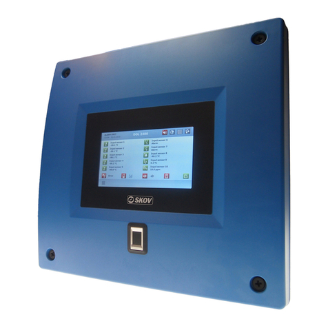
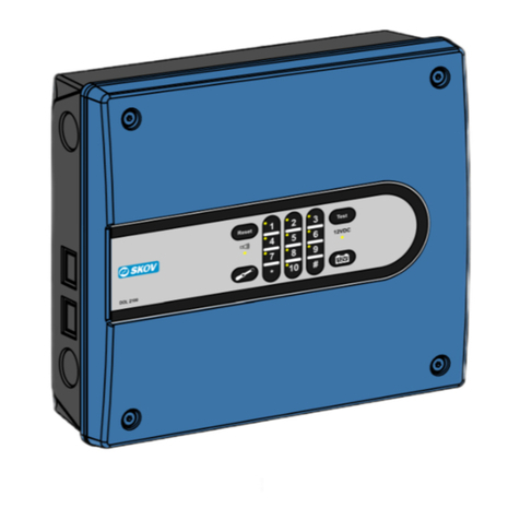
Skov DOL 2400 User manual

DOL 2400 • DOL 2300
Alarm System
User Manual
612541 • 2022-12-23 Software version 4.5
English For other language variants of this document we refer to:
Español Para otras variantes del idioma de este documento, visite:
Français Pour les versions dans d'autres langues de ce document veuillez consulter:
http://docs.skov.com/1095


DOL 2400 • DOL 2300
1 Product description ....................................................................................................................................... 5
2 User guide....................................................................................................................................................... 7
2.1 Handling alarms ......................................................................................................................... 8
2.1.1 Stop alarm with phone call........................................................................................................... 9
2.1.2 Stop alarm with SMS message.................................................................................................... 9
2.1.3 Video streaming via mobile in the event of an alarm ................................................................... 9
2.2 Pages ........................................................................................................................................ 10
2.2.1 The page Overview.................................................................................................................... 10
2.2.2 The page Outputs ...................................................................................................................... 12
2.2.3 The I/O Overview Page.............................................................................................................. 13
2.2.4 The page Activity log.................................................................................................................. 14
2.2.5 Select display language ............................................................................................................. 15
2.2.6 Editing and creating pages ........................................................................................................ 15
2.3 Settings..................................................................................................................................... 18
2.4 Remote control......................................................................................................................... 19
2.4.1 Entering phone numbers............................................................................................................ 19
2.4.2 SMS commands......................................................................................................................... 20
2.5 Voice messages from the alarm unit ..................................................................................... 21
2.6 Surveillance.............................................................................................................................. 22
2.6.1 Activation of surveillance ........................................................................................................... 22
2.6.2 Deactivation of surveillance alarm ............................................................................................. 22
2.7 Details menu............................................................................................................................. 23
2.7.1 Overview .................................................................................................................................... 23
2.7.2 Temperature alarms (Only DOL 2400) ..................................................................................... 24
2.7.2.1 Setting temperatur alarm limits .................................................................................................. 25
2.7.2.2 Temperature setpoint................................................................................................................. 25
2.7.2.3 Summer rise............................................................................................................................... 26
2.7.3 Log ............................................................................................................................................. 28
2.7.4 Function test .............................................................................................................................. 28
2.7.4.1 Manual test - with reminder........................................................................................................ 29
2.7.4.2 Automatic testing ....................................................................................................................... 29
2.7.5 Sound......................................................................................................................................... 30
2.7.6 System status ............................................................................................................................ 30
2.7.7 Supervision of the alarm unit’s input terminals .......................................................................... 31
2.7.7.1 Stop input supervision................................................................................................................ 31
2.7.8 Service break ............................................................................................................................. 32
2.8 Phone ........................................................................................................................................ 32
2.9 User login ................................................................................................................................. 34
3 Maintenance instructions ............................................................................................................................ 36
3.1 Recycling/Disposal .................................................................................................................. 36
4 Utility table for finished tests ...................................................................................................................... 37
User Manual

DOL 2400 • DOL 2300
4 User Manual
Product and Documentation Changes
SKOV A/S reserves the right to change this document and the product herein described without further notice.
In case of doubt, please contact SKOV A/S.
The date of change appears from the front and back pages.
In case of an operating error or improper use, alarm systems can cause production losses or the
loss of lives among animals.
SKOV A/S recommends that alarm systems be mounted, operated and serviced only by trained
staff and that the emergency opening and alarm system be maintained and tested at regular inter-
vals, in accordance with SKOV A/S´s terms and conditions of sales and delivery.
The installation must be carried out by an authorized electrician and according to current national
regulations and in the EU also applicable EU regulations.
SKOV A/S recommends that prepaid mobile service cards are not used for alarm units with mobile
modem.
SKOV A/S recommends that the alarm unit is connected to its own separate telephone line to en-
sure optimum use and safety. It is therefore important to avoid connecting the alarm unit together
with, e.g. a fax machine.
Note
• All rights belong to SKOV A/S. No part of this manual may be reproduced in any manner whatsoever without
the expressed written permission of SKOV A/S in each case.
• All reasonable efforts have been made to ensure the accuracy of the information contained in this manual.
Should any mistakes or imprecise information occur in spite of this, SKOV A/S would appreciate being noti-
fied thereof.
• Irrespective of the above, SKOV A/S shall not accept any liability with regard to loss or damage caused or
alleged to be caused by reliance on any information contained herein.
• Copyright by SKOV A/S.

DOL 2400 • DOL 2300
User Manual 5
1 Product description
The DOL 2400/DOL 2300 alarm system is primarily used to monitor ventilation in livestock houses. The alarm
system collects all incidents such as alarms and operation in a joint log, which can be used for analysis and sta-
tistics. The system can also be used for triggering alarms at equipment errors and other alarm situations.
Without extension the DOL 2400 can monitor the temperature in up to 20 house sections.
The alarm unit is not a fire alarm device, but when an additional sensor is connected to DOL 2400, it can signal
a rapid temperature rise, which may indicate an ignition in the building. This feature is for informational purposes
only and cannot replace a fire alarm. It is also possible to set up the DOL 2400 with surveillance to prevent
unauthorized visitors from entering livestock houses.
Camera
Outside temperature sensor
Silo and water alarm
Climate/Production
Mobile/fixed-line
Horn
Flash
Climate backup
Figure1: DOL 2400 alarm system
The alarm system consists of the DOL 2400/DOL 2300 alarm unit, input providers such as sensors and house
controllers, and alarm indicators such as horns or text messages.
The DOL 2300 is a reduced edition of the DOL 2400. The DOL 2300 is different from the DOL 2400 in that it
only has ON/OFF inputs and no climate backup and outputs. See the table ‘DOL 2400 and DOL 2300 function-
ality’.
The alarm unit is available in several variants - with or without a fingerprint reader - and two sizes - with 10 or 20
inputs. Depending on the variant DOL 2400/2300 can notify alarms in a clear voice and send warnings via SMS,
while the user can call or send an SMS to the unit to get alarm status or to acknowledge alarms. SMS is avail-
able when the alarm unit is fitted with a GSM modem. Furthermore, a fixed-line modem is available for areas
with poor mobile coverage.

DOL 2400 • DOL 2300
6 User Manual
Accessories
As an accessory, an extension box comes with a further ten terminal inputs. Up to eight extension boxes can be
connected to a large alarm unit and nine to a basic unit. Place the extension boxes immediately next to the
alarm unit. Another extension option is to use a DOL 2400/DOL 2300 in a Master/Client system. It can be done
in a LAN network, mainly where the alarm system covers a geographically large area. You can use up to nine
client units in the same system.
Functions DOL 2400 DOL 2300
Universal inputs:
• Temperature Yes No
• Digital ON/OFF Yes Yes
• Analogue Yes No
• Other sensor types (see below) Yes No
Outside temperature sensor Yes No
Phase break relay Yes Yes
Climate backup Yes No
Video streaming (SMS with browser view URL) Yes No
Outputs Yes No
Master/client Yes Yes
Surveillance Yes No
Table1: DOL 2400 and DOL 2300 functionality.
10" and 7" display
The displays shown in this manual are from a 10" display where the menu overview is shown to the left in the
display. If you use an alarm unit with a 7” display, the menus are shown in the middle of the display.
Using a 7” display you can press the menu headlines at the top
of the display to go back step-by-step in the menus.
If more steps are available that what can be shown, you can
press the 3 dots and select a menu from the appearing list.

DOL 2400 • DOL 2300
User Manual 7
2 User guide
The alarm unit is operated by means of the touch display.
The view in the display is called a page. One page can contain more information than what you can immediately
see, and you can scroll up and down on the page.
BDE
F
G H I J K
L
A
C
Figure2: 10" display.
BDE
F
L
G
H
I
J
A
K
C
Figure3: 7" display.
AThe page content.
BShortcuts to available pages.
CShortcut to activity log.
DThe name of the alarm unit and the time of day.
EThe icon and name of the displayed page.
FAccess to Settings and language selection. See also Select display language [}15].
GDisplay of outside temperature, if outside temperature sensor is connected. Not possible for all vari-
ants.
HDisplay of telephone status. See also Remote control [}19].
IDisplay of the phase break status. See also the Technical Manual.
JDisplay of the battery status. See also Maintenance instructions [}36].

DOL 2400 • DOL 2300
8 User Manual
KDisplay of the output status.
LAccess to page setup. See also Editing and creating pages [}15].
The colors of the icons, the text and lines on the pages show the current status of the function.
Green: All is OK
Red: Alarm
Yellow: Supervision of the function is disabled
Orange: The livestock house is set for service break / warning
Empty: Nothing is installed on this input
2.1 Handling alarms
The alarm units displays the alarms as a pop-up.
There are two types of alarm:
Hard alarm:
Red alarm pop-up on the alarm unit. At the same time local
alarms such as horns and flashes are triggered, and alarms are
also sent by phone calls and SMS message.
Silent alarm (soft):
Yellow warning pop-up on the alarm unit and registration in the
activity log.
See the Technical Manual about setting up inputs.
In the event of a power failure, local alarms with horns and
flashes will change from constant to pulsing.
The icon for the activity log indicates the number of active
alarms, as long as an alarm situation has not ended.
The icon for the inputs with alarm is also red/yellow on the page
Overview.

DOL 2400 • DOL 2300
User Manual 9
Acknowledging alarms
Press Acknowledge to stop the alarm and calls.
Alarms can also be acknowledged by:
• sending an SMS message to the alarm unit. See Stop alarm
with phone call [}9].
• calling the alarm unit. See Stop alarm with phone call
[}9].
• acknowledging the alarm via the management programme
FarmOnline Explorer.
The alarm unit cannot be operated before alarms have been ac-
knowledged.
Login
The alarm unit can be set up so that the user must log in - with code or fingerprint (applies only to alarm units
with fingerprint scanner) - to be able to acknowledge alarms. See User login [}34].
Temporary remote acknowledgment - snooze
The alarm unit can be set up for temporary alarm acknowledg-
ment via phone, SMS message or FarmOnline Explorer. If the
alarm situation continues, the alarm unit activates the alarm
again after 15 minutes (setting).
See the Technical Manual.
2.1.1 Stop alarm with phone call
In case of alarm the alarm unit makes a call (only with mobile ((GSM)) or fixed-line modem).
• Stop the alarm by answering the call and pressing 1 on the phone to acknowledge the alarm. Press 2 for the
next alarm. Press 9 to repeat the alarm.
• The alarm unit acknowledges the alarm.
2.1.2 Stop alarm with SMS message
In case of alarm the alarm unit sends an SMS message (only with mobile modem).
• Stop the alarm by responding to the SMS alarm and sending the text ACK.
• The alarm unit acknowledges the alarm and sends an SMS confirmation stating that the alarm has been ac-
knowledged.
2.1.3 Video streaming via mobile in the event of an alarm
• DOL 2400 can can connect up to 20 cameras, which can display what is happening in the livestock house
during an alarm.
• DOL 2400's alarm SMS message can include a link to a web camera in the alarm location. As such, it is
possible to gain access to the live streaming from the camera.

DOL 2400 • DOL 2300
10 User Manual
2.2 Pages
We recommend that you create a number of pages to show exactly the necessary functions and values and
cover the needs of the daily user. See also Editing and creating pages [}15].
The pages work as shortcuts to the key values and settings and therefore gives you quick access to reading val-
ues and changing some settings.
The individual key values shown on the pages are also called cards.
2.2.1 The page Overview
Gives an overview of the installed alarm inputs and their status and provides a shortcut to the setup of the in-
puts. Each input appears as a card on the page.
C
D
A
B
E
AThe icon for the Overview page.
BThe icon and name of the displayed page.
CCard for the each input.
DThe color of the card shows the current status of the input.
No color: OK
Red: Alarm
Yellow: Warning
Grey: Supervision of the input is paused
EThe 3 dots indicate that pressing the card will display additional information and give access to reading
current values and settings and to enable or disable supervision of the input.
Depending on the type of input pressed, the card will display additional information such as:
Supervision Enabling and disabling supervision of the input. See the section Stop input super-
vision [}31].
Setpoint The set value for the input.
Alarm limit The value that will trigger the alarm if exceeded.

DOL 2400 • DOL 2300
User Manual 11
Info Information about the input, such as, name, status, current value, type, settings,
etc.
History History curve for the input.

DOL 2400 • DOL 2300
12 User Manual
2.2.2 The page Outputs
Gives an overview of the installed outputs and their status and provides a shortcut to the setup of the outputs.
Each output appears as a card on the page.
C
E
A
B
D
AThe icon for the Outputs page.
BThe icon and name of the displayed page.
CCard for the individual output.
The color of the card shows the current status of the output.
Green: Everything is OK
Red: Alarm
DThe three dots indicate that pressing the card will display additional information about the output and
give access to reading current values and settings.
EThe symbol shows if the output type is Normally open or Normally closed. See also the Technical
Manual.
Depending on the type of output being pressed, the card will display additional information such as:
Relay status Information whether the function is active or not.
Output type Information about the selected type of output.
Relay type Information about the selected type of relay.
Input Information about which input may be connected to the output.
For information about the function Climate Backup, see .

DOL 2400 • DOL 2300
User Manual 13
2.2.3 The I/O Overview Page
Provides an overview of the alarm status of the installed I/O modules and a shortcut for reading and setting up
each input. Each input appears as a card on the page.
AThe icon for the I/O alarm overview page. Press the icon to open the I/O overview.
The color indicates the status.
Green: Everything is OK
Red: Alarm
Touch a row to open a page with a detailed status of the vari-
ous inputs.
A
B
D
C
BThe icon for the Input page.
CCard for the each input.
DThe three dots indicate that pressing the card will display additional information about the input and
give access to reading current values and settings.

DOL 2400 • DOL 2300
14 User Manual
2.2.4 The page Activity log
The alarm unit registers operation, events and alarms with the information of when they took place and when
they were deactivated.
The activity log contains information about alarms:
• When the alarm occurred.
• When the alarm ended.
• The value that triggered the alarm.
Active alarms are marked in the list.
• Hard alarms are marked in red.
• Soft alarms are marked in yellow.
• Deactivated alarms are gray.
The icon for the activity log indicates the number of active alarms, as long as an alarm situation has not ended.
C
F
A
B
D
G
H
E
AThe icon for the Activity log page.
BThe icon and name of the displayed page.
CThe number of active alarms.
DWhen the activity occurred and the duration.
EPress an activity to see additional information, for example, who acknowledged the alarm.
FDisplay of the various types of activities
All: shows all types
Alarm: shows only alarms
Operation: shows operation of the alarm unit
Event: shows, for example, restart of the alarm unit
GIt is possible to filter the activity log to see only activities for specific inputs or alarms.
HSearch the activity log by entering a search word.

DOL 2400 • DOL 2300
User Manual 15
Press > to hear the one minute audio file recorded by the alarm
unit when the alarm occurred.
2.2.5 Select display language
Press to open the menu. The selected language is shown with a tick mark.
If the requested language is not shown. Press More and select
the language from the list. Press Confirm.
Note that names of, for example, pages, inputs and outputs which can be named by the user are not translated
into the selected language. They have English names from the factory until they are changed by the user.
Once user management is active, the display language will adapt according to the user who is logged in. See
User login [}34] and the Technical Manual for activation of user management.
2.2.6 Editing and creating pages
The alarm unit comes with 3 default pages. The pages can be edited by the user and additional pages can be
added.

DOL 2400 • DOL 2300
16 User Manual
Press the gear wheel icon in the bottom right corner.
Select Add and edit.
Select the requested content for the page (cards). Inputs and
outputs can be shown on the same page.
A
C
B
D
APress the one of the tools to select card display, edit their content, to move or delete the cards.
Show cards in 2 columns (only applies to some variants)
Show cards in 4 columns (only applies to some variants)
Edit
Move
Delete
BWhen a tool is selected, the icons on the cards change to reflect the tool.
CAdd more cards.
DFinish the setup by pressing Confirm.

DOL 2400 • DOL 2300
User Manual 17
To layout the columns as you want or to group cards, you can
also insert Empty cards.
Create new page
When a new page is created, you can select if a shortcut to that page should always be shown in the display. A
maximum of 5 shortcuts can be shown here. Pages without shortcuts are shown when you press the Overview
.
Press General | Manage pages.
Press New page.
Name the page.
Select a suitable icon for the page content to easily recognize it.
Press Go to page to be able to select the content on the page.
The new page is displayed.
Press the gear wheel icon in the bottom right corner and select
Add and edit to set up the page as described earlier.

DOL 2400 • DOL 2300
18 User Manual
2.3 Settings
The settings menu is opened by pressing Overview and then Settings .
The display will show the menu that was last opened.
Values in white fields can be edited. Press the field to access
the value change dialog.
Search in menus
Use the search field to search in menus. Enter at least 3 char-
acters to search.
The result is shown below the search field.
The path for the individual menus is also shown.
Press a search result to go directly to that menu.
Press the X at the search field to remove the search results
again.
Changing the settings
Use the number keys to enter a value.
The current value, minimum and maximum available setting is
shown below the line.
Press the x to delete the value, press Cancel to discard the set-
ting or Confirm to confirm the new setting.
Activating/deactivating functions
Functions can be activated and deactivated by means of the
toggle button.

DOL 2400 • DOL 2300
User Manual 19
Scroll up/down
If the page or menu is higher than the display, you can scroll
up/down.
The possibility to scroll is shown by the arrows in the display.
You can scroll by pressing the arrows or letting your finger slide
across the display.
Scroll right/left
If the page or menu is wider than the display, you can scroll
right/left.
The option of scrolling right/left can be seen by the shadow in
the first column in the menu.
You can scroll by letting your finger slide across the display.
2.4 Remote control
As accessories for the alarm unit, a GSM telephone modem and a fixed-line (PSTN) telephone modem are also
available. This allows for remote control through phone calls or SMS messages.
Only the nine phone numbers included in the alarm unit call list have access to calling and sending SMS mes-
sages to the alarm unit.
Press the shortcut for telephone in the display to see the status of the telephone.
Call sequence The alarm unit sends the alarm to the first number in the list by means of a call
and/or SMS message. If the first number in the list does not respond or acknowl-
edge, the alarm unit contacts the next number in the list.
GSM (mobile): Information if the mobile modem is activated.
GSM signal strength Display of the current GSM (mobile) signal strength.
GSM signal history Trend curve of the GSM signal.
Fixed line Information if the fixed-line modem is activated.
Delay before call Display of the delay from start of alarm until the alarm unit calls out in case of
alarm.
Call attempt time Display of the time the alarm unit leaves the call active if no response is given. It
the user does not respond to the call, the alarm unit calls the next number in the
call list.
Delay between SMS (mobile): Display of the time before the alarm unit sends a new SMS message.
2.4.1 Entering phone numbers
Enter up to 9 phone numbers the alarm unit should contact in case of alarm. The alarm unit uses the list as a
sequence for contacts. If the first number in the list does not respond and acknowledge, the alarm unit contacts
the next number in the list.
If you have different contact to handle specific alarms, it is also possible to connect specific inputs to a specific
telephone number. The alarm unit will in that case always contact this number first and then use the list, if this
phone number does not respond. See also the Technical Manual for setup of alarm inputs.
Select the menu Phone | Installation | Phone numbers

DOL 2400 • DOL 2300
20 User Manual
Enter telephone numbers.
Select the wanted number of redials for each phone number be-
fore a call is made / an SMS message is sent to the next phone
number.
Select whether the contact should receive a call, an SMS mes-
sage, or both.
Select the language the alarm unit should provide the alarm
message in.
Enter name of the contact.
Carry out a test to confirm that the alarm unit can call and send
SMS messages to the number entered. This way the users also
get the number to the alarm unit so that they can send SMS
messages to the alarm unit.
See also the Technical Manual for more about telephone setup
and to gain an overview of the calling process during an alarm.
2.4.2 SMS commands
Send an SMS message with a standard command to the alarm unit. The alarm unit primarily responds with sta-
tus information, but it is also possible to acknowledge alarms and change the order of the call sequence list.
Operation Standard command, send
SMS message
The alarm unit responds (examples)
See a list of commands HELP ALARM
ACK
CALL
STATUS
SETUP
OUTPUT
ARM
DISARM
See current alarm sta-
tus
ALARM
ALARM 3
Alarms from all inputs.
ALARM (input number)
Alarm from input
Acknowledge alarm
(If user management is
active)
ACK
ACK 176
ACK 487298
ACK 176 487298
Acknowledge all alarms.
ACK (ID)
Acknowledge alarm with ID.
ACK (PIN)
Acknowledge all alarms.
ACK (ID) (PIN CODE)
Acknowledge alarm with ID.
See call list CALL 1 20304050
2 30405060
3 40506070
-
Enter which number the
alarm unit should con-
tact first
CALL (1-10) 1 30405060
2 20304050
3 40506070
4 50607080
-
Other manuals for DOL 2400
1
This manual suits for next models
1
Table of contents
Other Skov Security System manuals