SECUBEST PTI400 User manual

Wall/Ceiling/All in One/In-ceiling
Camera
x39 IP PTZ
Ver. 1.1/ 2013.06
User’s Manual
Before installing and using the camera, please read this manual carefully.
Be sure to keep it handy for future reference.

Safety Information
This symbol indicates that dangerous voltage
consisting a risk of electric shock is present within
this unit.
Warning Precaution
This exclamation point symbol is intended to alert the
user to the presence of important operating and
maintenance (servicing) instructions in the literature
accompanying the appliance.
TO REDUCE THE RISK OF ELECTRIC SHOCK, DO NOT REMOVE COVER (OR BACK) NO USER SERVICEABLE
PARTS INSIDE. REFER SERVICING TO QUALIFIED SERVICE PERSONNEL.
CAUTION:
CAUTION
RISK OF ELECTRIC SHOCK.
DO NOT OPEN.
To prevent damage which may result in fire or electric shock
hazard, do not expose this appliance to rain or moisture.
WARNING
Be sure to use only the standard adapter that is specified in
the specification sheet. Using any other adapter could cause
fire, electrical shock, or damage to the product.
Incorrectly connecting the power supply or replacing battery
may cause explosion, fire, electric shock, or damage to the
product.
Do not connect multiple cameras to a single adapter.
Exceeding the capacity may cause excessive heat generation
or fire.
Securely plug the power cord into the power receptacle.
Insecure connection may cause fire.
When installing the camera, fasten it securely and firmly.
A falling camera may cause personal injury.
Do not place conductive objects (e.g. screw drivers, coins,
metal items, etc.) or containers filled with water on top of
the camera. Doing so may cause personal injury due to fire,
electric shock, or falling objects.
Do not install the unit in humid, dusty, or sooty locations.
Doing so may cause fire or electric shock.
If any unusual smells or smoke come from the unit, stop
using the product. Immediately disconnect the power sorce
and contact the service center. Continued use in such a
condition may cause fire or electric shock.
If this product fails to operate normally, contact the nearest
service center. Never disassemble or modify this product in
any way.
When cleaning, do not spray water directly onto parts of the
product. Doing so may cause fire or electric shock.
WARNING
1.
2.
3.
4.
5.
6.
7.
8.
9.
10.
Precaution
Operating
t Before using, make sure power supply and all other parts are
properly connected.
tWhile operating, if any abnormal condition or malfunction
is observed, stop using the camera immediately and contact
your dealer.
Handling
tDo not disassemble or tamper with parts inside the camera.
tDo not drop the camera or subject it to shock or vibration as
this can damage the camera.
tClean the clear dome cover with extra care. Scratches and
dust can ruin the quality of the camera image.
Installation and Storage
tDo not install the camera in areas of extreme temperature,
exceeding the allowed range.
tAvoid installing in humid or dusty environments.
tAvoid installing in places where radiation is present.
tAvoid installing in places where there are strong magnetic
elds and electric signals.
tAvoid installing in places where the camera would be subject
to strong vibrations.
tNever expose the camera to rain or water.
2

Important Safety Instructions
1. Read these instructions. - All these safety and operating instructions should be read before the product is
installed or operated.
2. Keep these instructions. - The safety, operating and use instructions should be retained for future reference.
3. Heed all warnings. - All warnings on the product and in the operating instructions should be adhered to.
4. Follow all instructions. - All operating and use instructions should be followed.
5. Do not use this device near water. - For example: near a bath tub, wash bowl, kitchen sink, laundry tub, in a wet
basement; near a swimming pool; etc.
6. Clean only with dry cloth. - Unplug this product from the wall outlet before cleaning. Do not use liquid cleaners.
7. Do not block any ventilation openings. Install in accordance with the manufacturer’s instructions. - Slots and
openings in the cabinet are provided for ventilation, to ensure reliable operation of the product, and to protect it
from over-heating. The openings should never be blocked by placing the product on bed, sofa, rug or other similar
surface. This product should not be placed in a built-in installation such as a bookcase or rack unless proper
ventilation is provided and the manufacturer’s unstructions have been adhere to.
8. Do not install near any heat sources such as radiators, heat registers, or other apparatus (including ampliers)
that produce heat.
9. Do not defeat the safety purpose of the polarized or grounding-type plug. A polarized plug has two blades with
one wider than the other. A grounding type plug has two blades and a third grounding prong. The wide blade
or the third prong are provided for your safety. If the provided plug does not t into your outlet, consult an
electrician for replacement of the obsolete outlet.
10. Protect the power cord from being walked on or pinched particularly at plugs, convenience receptacles, and
the point where they exit from the apparatus.
11. Only use attachments/accessories specied by the manufacturer.
12. Use only with cart, stand, tripod, bracket, or table specied by the
manufacturer, or sold with the apparatus. When a cart is used, use
caution when moving the cart/apparatus combination to avoid
injury from tip-over.
13. Unplug this apparatus during lightning storms or when unused for long periods of time.
14. Refer all servicing to qualied service personnel. Servicing is required when the apparatus has been damaged
in any way, such as power supply cord or plug is damaged, liquid has been spilled or objects have fallen into the
apparatus, the apparatus has been exposed to rain or moisture, does not operate normally, or has been
dropped.
3

Disposal of Old Appliances
1. When this crossed-out wheel bin symbol is attached to a product it means the product is covered by
the European Directive 2002/96/EC.
2. All electrical and electronic products should be disposed of separately form the municipal waste
stream stream in accordance to laws designated by the government or the local authorities.
3. The correct disposal of your old appliance will help prevent potential negative consequences for
the environment and human health.
4. For more detailed information about disposal of your old appliance, please contact your city oce,
waste disposal service or the shop where you purchased the product.
This equipment has been tested and found to comply with the limits for a Class A digital device, pursuant to part 15 of the FCC Rules.
These limits are designed to provide reasonable protection against harmful interference when the equipment is operated in a commercial environment.
This equipment generates, uses, and can radiate radio frequency energy and, if not installed and used in accordance with the instruction manual, may cause
harmful interference to radio communications. Operation of this equipment in a residential area is likely to cause harmful interference in which case the user
will be required to correct the interferenece at his own expense.
4

Product & Accessories
Wall/Ceiling Mount Camera Introduction -
Wall Mount Type
Ceiling Mount Type
Housing Safety
Cable Hanger
Water Proof Tape
Hole Template
Hexagonal Wrench
Manual CD
Anchor Bolt(4pcs)
Safety Wire
Product Accessories
Quick Manual
5

Product & Accessories
All in One Camera Introduction -
All-In-One Camera Manual CD
Hexagonal Wrench
Product Accessories
Quick Manual
Ferrite Core
6

Product & Accessories
In-ceiling Camera Introduction -
Manual CD
Product Accessories
Quick Manual
Dome Cover
In-ceiling Housing
with PTZ Mechanism
Safety Wire x2
7

Part Name & Functions
Wall/Ceiling Mount Camera Introduction -
1
1
2
2
3
3
6
4
4
5
6
Wall/Ceiling Mount Bracket
These are used to install the camera on the wall or ceiling
and have junction box. The wall/ceiling mount bracket
accommodate the junction box.
Sun-shield & Upper Housing
5Dome Safety Wire
PTZ Mechanism
Junction Box
Housing Safety
Wire Hanger
Wall Mount Bracket
Ceiling Mount Bracket
Junction Box
The inner has many important roles of connection box
between camera and outside. Top of the box, there are dip
switches and terminal locks for power supply, video,
communication, alarm input/output.
Sun-shield & Upper Housing
Sunshield protect bubble dome cover from the sun rays and
rain fall. In the sunshield, there is the upper housing which
will contain accommodate PTZ mechanism. In the upper
housing, there are fan and heater to remove moisture on
the bubble dome. Also, the upper housing will be
connected to both mounting brackets and dome cover.
PTZ Mechanism
Control the PTZ operations of the camera.
Dome Safety Wire
Prevents the dome cover from falling.
Dome Cover
Do not detach protection lm from dome cover before
finishing all installation process to protect dome cover from
scratches or dust.
Dome Cover
8

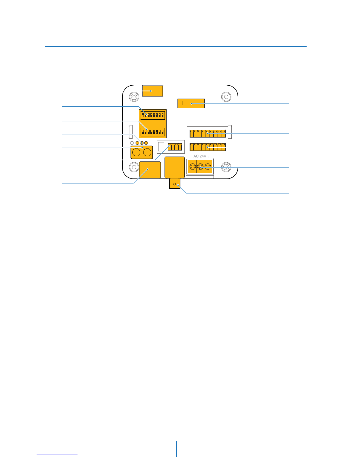
Part Name & Functions_Junction Box
Wall/Ceiling Mount Camera Introduction -
RS-485
Address DIP Switch
Protocol DIP Switch
Power, Active, Locked Light Alarm Out
Alarm In
RJ-45
Main Connector
Power
Test Video Out
Audio In/Out
Micro SD Card Slot
8
9
10
11
12
1
2
3
4
5
6
7
9

Part Name & Functions_Appearance
All in One Camera Introduction -
3
4
Dome Safety Wire
Prevents the dome cover from falling.
Dome Cover
Do not detach protection lm from dome cover before
finishing all installation process to protect dome cover
from scratches or dust. In the dome cover, there are fan
and heater to remove moisture on the bubble dome.
1
2
Sunshield & Upper Housing
Sunshield protect bubble dome cover from the sun rays and
rain fall. In the sunshield, there is the upper housing which
will contain accommodate PTZ mechanism. Also, the upper
housing will be connected to both mounting brackets and
dome cover.
PTZ Mechanism
Control the PTZ operations of the camera.
1
Sunshield & Upper Housing
2
PTZ Mechanism
3
Dome Safety Wire
4
Dome Cover
10

Part Name & Functions_Inside
All in One Camera Introduction -
6
7
8
9
10
11
12
Audio Output Port
Used to connect the audio output cable.
Audio Input Port
Used to connect the audio input cable.
ID Setup Switch
Specify the camera ID.
Communication Setup Switch
Set the transfer rate and protocols.
Micro SD Memory Card Slot & Cover
RS-485 Port
Used for RS-485 communications.
Power Port
Connect the power source here.
1
2
3
4
5
Alarm Output Port
It connects to the alarm lights, siren or lamps, and it is
activated according to the OSD menu or ‘Setup’ on the Web
-viewer setting.
Alarm Input Port
It connects to IR sensor, IrDA sensor or door switch. If the
sensor is activated, it can activate to move camera to the
specic angle and to connect the alarm device.
Network Cable Port
Connect the crossover cable.
Fan
Defrosts the dome cover and removes moisture.
Heater
Defrost the dome cover in a low temperature by increasing
the internal temperature of the housing.
Alarm Output Port
Alarm Input Port
Network Cable Port
Fan
Heater
Audio Output Port
Audio Input Port
ID Setup Switch
Communication
Setup Switch
Micro SD Card Slot
& Cover
RS-485 Port
Power Port
1
2
3
4
5
6
7
8
9
10
11
12
11

Part Name & Functions_Appearance
In-ceiling Camera Introduction -
Dome Cover Hooks
Dome Cover
Dome Cover Side Hole
PTZ Mechanism
PTZ Mechanism Hook
In-ceiling Housing
PTZ Mechanism Hook Guide
Mounting Clip
Inceiling Housing Border
Mounting Clip Bolt
Housing Safety Wire Hanger
Junction Box
Junction Box Hook
Junction Box Cover
Junction Box Cover Side Hole
12
Part Name & Functions_Junction Box
In-ceiling Camera Introduction -
RS-485
Address DIP Switch
Protocol DIP Switch
Power, Active, Locked Light Alarm Out
Alarm In
RJ-45
Main Connector
Power
Video Output
Audio In/Out
Micro SD Card Slot
13
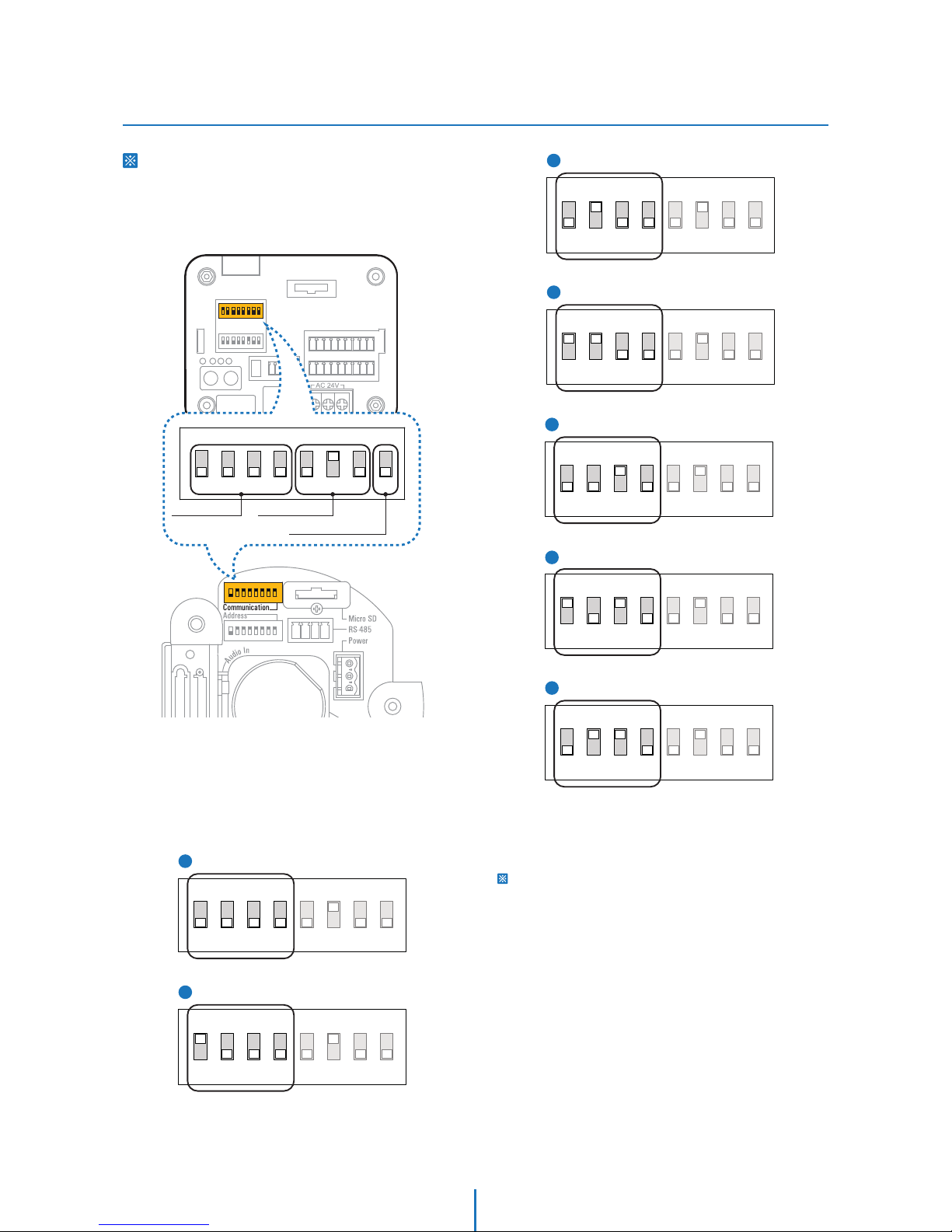
DIP Switch Setup
Installation -
Before installing the camera, set up the DIP
switch to configure the Camera ID,
communication protocol.
Junction Box
1. Communication Protocol Setup
Select the appropriate protocol with DIP switch combination.
Protocol Setup Baud Rate Setup RS-485
Termination Resistor
ON
8J 21 345678
1Auto - Factory Default
ON
8J 21345678
2
ON
8J
21345678
PELCO-D
3
ON
8J
21345678
PELCO-P
4
5
6
7
SAMSUNG
ON
21345678
Panasonic
8J
ON
21345678
GE(Kalatel)
8J
ON
21345678
AD(American Dynamics)
ON
8J
21345678
Interface Board of All in One Camera
- When the communication protocol setting is ‘Auto’, camera
will recognize SAMSUNG-E or PELCO-D / P protocol
automatically.
Any other DIP switch combinations will be recognized as Auto
protocol.
- If you want to control the camera using a DVR or a keyboard
controller, the protocol must be identical to the protocol set
on the camer.
- If you change the camera protocol by changing the DIP
switch, the change will be eective only after you reboot the
camera.
14
DIP Switch Setup
Installation -
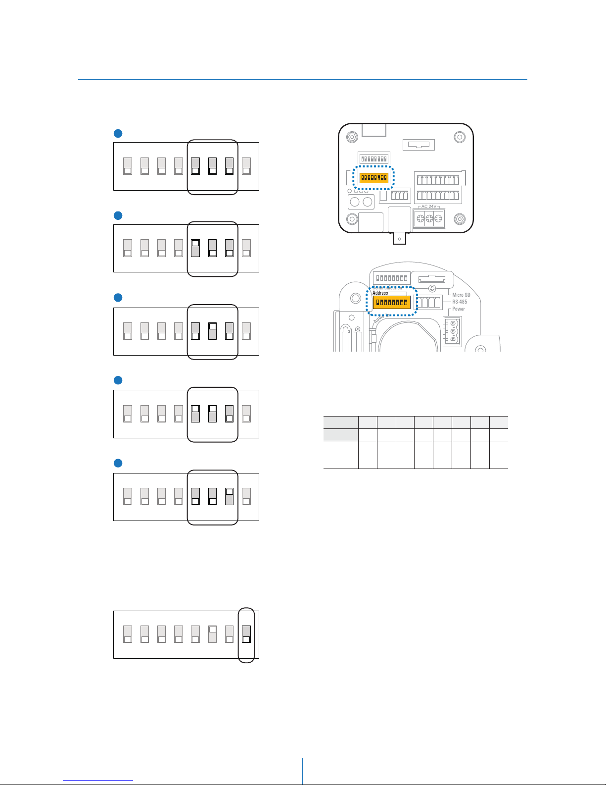
2. Communication Baud Rate Setup
Select the appropriate baud rate with DIP switch combination.
1
2
3
4
5
ON
8J
21345678
2400 BPS - Factory Default
ON
8J
21345678
4800 BPS
ON
8J
21345678
9600 BPS
ON
8J
21345678
19200 BPS
38400 BPS
ON
8J
21345678
ON
8J 21 345678
4. Camera ID Setup
Junction Box
The ID number of the camera is set using binary numbers.
See the example below.
Pin 1234 56 78
1 2 4 8 16 32 64 128ID Value
ex) ID=5
ex) ID=10
on
off
off
on
on
off
off
on
off
off
off
off
off
off
off
off
- If you want to control a certain camera, you must match the
camera ID with ‘CAM ID’ setting of DVR or keyboard controller.
- The range of Camera ID is 0~255.
- All cameras have a factory default Camera ID of 1.
- Camera ID will be effective without having to reboot the
camera.
3. RS-485 Termination Resistor
- Pin 8 is used for on/off of RS-485 termination.
- Normally, it must be OFF.
- When you have trouble with long daisy chain style connections,
turn ON this termination switch on the last camera.
Interface Board of All in One Camera
15

Installation
Wall/Ceiling Mount Camera Installation -
2
1
3
Using the mount template sheet, mark the holes on the
wall or ceiling.
After drilling the holes, x the four anchor bolts into the
holes.
Place the wall/ceiling mount bracket on the anchor bolts
properly and tighten the nuts on the anchor bolts.
Ceiling Mount Bracket
Installation
Wall Mount Bracket
Installation
16

Detach the PTZ mechanism from the upper housing to plug
the main cable. When detaching the PTZ mechanism, press
down and hold up the black handles on both sides of the
PTZ mechanism.
Remove the protecting tape used to fix the PTZ
mechanism.
5
RS-485
BNC Video
Power
Crossover Cable
4Connect each of the following cables to the applicable slots
and set the DIP switch to congure the camera ID and
communication protocol.
RS-485 Port
Protocol,
Address DIP Switch
Test Video Out
Alarm Out
Micro SD
Card Slot
Alarm In
Power
Junction Box
Main Connector
Audio In/Out
RJ 45
Installation
Wall/Ceiling Mount Camera Installation -
See the section ‘Installation - DIP Switch Setup’ for detail.
See the section ‘Installation - Cabling’ for detail.
See the section ‘Installation - Inserting/Removing an SD
Memory Card’ for detail.
17

Plug the main cable into the main connector in the upper
housing and press the main cable till it sounds snap to lock.
7
[2]
[1]
[3]
6[1] Wind the waterproof tape around the pipe of housing.
[2] Hook the safety wire on the hole of pipe and the housing
safety cable hanger.
[3] Attach the upper housing to wall mount bracket by
turning it at least seven turns.
To secure the orientation of the housing, turn the ring
cap counter-clockwise until it is tight.
Installation
Wall/Ceiling Mount Camera Installation -
18

9Align ‘A’, ’B’ mark of one touch connector in the upper
housing with the two black handles of PTZ mechanism,
and insert the PTZ mechanism into hook in the upper
housing.
Connect the dome satety wire into the connectors in the
upper housing.
8
Installation
Wall/Ceiling Mount Camera Installation -
19

Installation
Wall/Ceiling Mount Camera Installation -
12
11
10
Close the dome cover. Match the arrow mark on the dome
cover and the housing.
Tighten four screws on the dome cover in the sequence
shown in the image below.
To maintain the best sealing, the torque of each screw
must be in the range of 0.5 ~ 1.0 N·m(0.3 ~ 0.73 lbf·ft).
Arrow Mark
Arrow Mark
To lock the PTZ mechanism to the upper housing, press
the two black handles until a snap sound is heard.
20
Table of contents


