Securakey ET-SR-X-K User manual
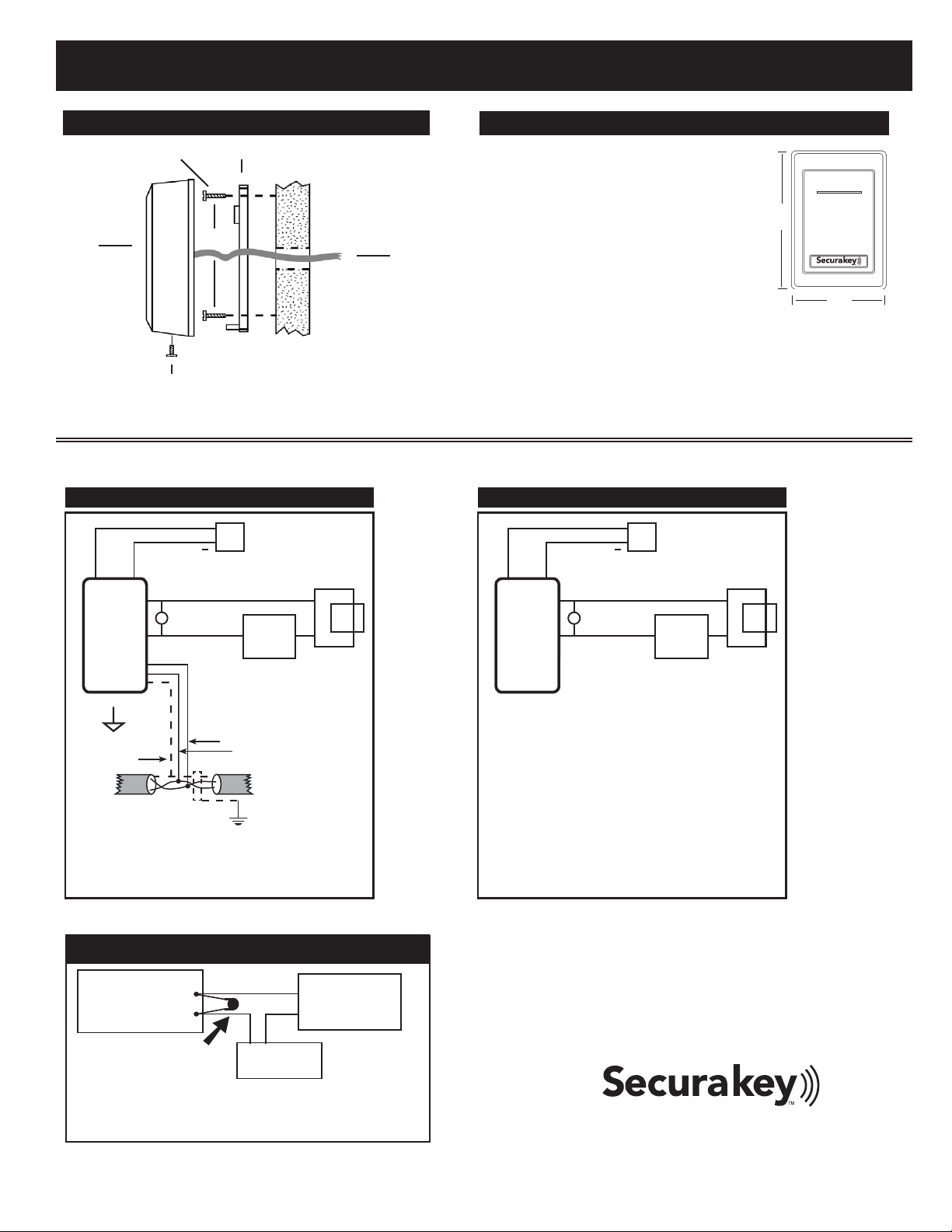
SWITCHPLATE INSTALLATION DIAGRAM
Mounting Plate
Reader
Housing
Mounting
Surface
¿
¿
Use appropriate
Fastener
¿
Use supplied
screw
¿
3/4” diameter
through hole
for cables.
¿
¿
¿
3.28
3322328 7744
1. If mounting the unit outdoors, especially on a
rough surface like masonry, we recommend
that you seal the reader with silicone caulking.
2. Drill holes as needed per installation
diagram shown to the left or install a single
gang j-box.
3. Run eld wiring to reader location and feed
into j-box or through cable hole.
4. Attach the mounting plate to the mounting
surface or j-box with the appropriate
fasteners.
5. Splice the connector pigtail to eld wiring.
Insert the connector into the back of the reader.
6. Attach the housing to the mounting plate by inserting the two tabs
inside the top of the housing into the two slots at the top of the
mounting plate.
7. Secure by installing supplied screw into the hole at the bottom of
the reader.
INSTALLATION STEPS FOR RKDT-SR-S:
¿
3.20
4.50
¿
¿
¿
OUTPUT RELAY
REMOTE OPEN
TYPICAL INSTALLATION
LOCK
POWER
SUPPLY
12
VDC
+
MAGLOCK*/
STRIKE
WHITE/BROWN
WHITE/BLACK
RED
BLACK
VOM
POWER
SUPPLY
READER
* Relay defaults to Normally Open.
Note: Use separate power supplies for maglock / strike
and for access control unit.
Do NOT connect Signal Ground to Earth Ground.
Line A GRAY
Line B VIOLET
DC SIGNAL
GROUND -
BLACK
EARTH
GROUND
MAGLOCK /
STRIKE
ACCESS
CONTROL
UNIT
LOCK
POWER
SUPPLY
DC
+
_
RELAY +
RELAY -
INSTALL
MOV HERE
INSTALLATION OF METAL OXIDE VARISTOR
Install the enclosed 40-volt MOV (Metal Oxide Varistor) across
the relay contacts in the access control unit, as shown. The
Access Control Unit must have its own power supply.
RKDT-SR-M / RKDT-SR-S Installation Instructions
4.38”
1.74”
3.14”
.90”
4.38”
1.74”
3.14”
.90”
MULLION INSTALLATION DIAGRAM
Use supplied screws
3/4” Diameter hole in
mounting surface for
wiring
l
Mounting
Surface
l
1. If mounting the unit outdoors, especially
on a rough surface like masonry, we
recommend that you seal the reader with
silicone caulking.
2. Drill a hole for the eld wiring. Remove
decorative cover from reader. Using the
reader as a template, mark the location of
the two mounting holes. Drill two 1/8” pilot
holes for the mounting screws.
3. Run eld wiring to reader location and feed
through cable hole.
4. Splice the connector pigtail to eld wiring.
Insert the connector into the back of the
reader.
5. Attach the reader to the surface using the two machine screws
provided. These may be replaced with tamper proof screws
(customer supplied).
6. Slip on the decorative cover (if used) until both tabs snap into place.
INSTALLATION STEPS FOR RKDT-SR-M
20301 Nordhoff Street, Chatsworth, CA 91311
PHONE (818) 882-0020 • FAX (818) 882-7052
TOLL-FREE (800) 891-0020
Website: www.securakey.com • E-mail: mail@securakey.com
ET-SR-X-K ET-SR-R-S / ET-SR-R-K
ET-SR-X-K / ET-SR-R-S / ET-SR-R-K Installation Instructions
Access Control Unit
MOV
Installation Instructions
Mounting Plate
2, #6 Mounting Screws
1, 4x40 Screw
1, Security Screw
1, Cable Assembly
ACCESSORIES (NOT INCLUDED):
RK-PS: 9VDC Plug-in Power Supply. It is designed
to power the Reader. Requires
110 Volts AC power.
SK-SR SecuRelay™ - Smart Relay Module DPDT.
3322328 7744
20301 Nordhoff Street, Chatsworth, CA 91311
PHONE (818) 882-0020 • FAX (818) 882-7052
TOLL-FREE (800) 891-0020
www.securakey.com • mail@securakey.com
INSTRUCTION TO THE USER
FCC ID: NNHETXXX
“This device complies with Part 15 of the FCC rules. Operation is subject to the following two conditions: (1) this device may not cause harmful interference, and
(2) this device must accept any interference received, including interference that may cause undesired operation.”
regulations, shielded cables must be used with this equipment. Operation with non-approved equipment or unshielded cables is likely to result in interference to
authority to operate this equipment.
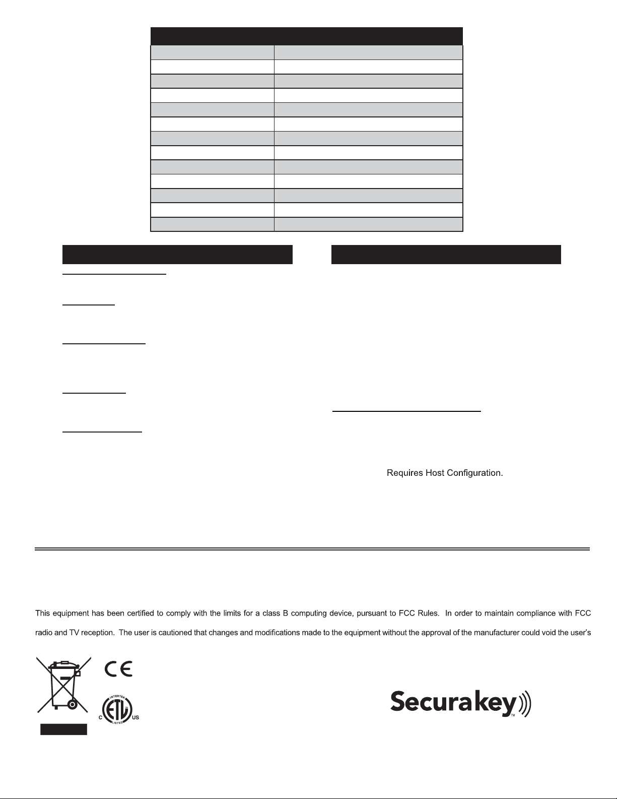
WIRING CONNECTIONS
WIRE COLOR RKDT-SR-M / SR-S
GREEN Open Collector 1
WHITE Open Collector 2
VIOLET RS-485-B
GRAY RS-485-A
ORANGE Input 1
BROWN Input 2
YELLOW Input 3
BLUE Input 4
RED 5-14VDC +
BLACK DC Ground
WHITE/BLACK RELAY
WHITE/BROWN RELAY
SPECIFICATIONS:
RoHS
3059349
PARTS SUPPLIED:
POWER REQUIREMENTS
5-14 VDC, Avg. 200 mA
INDICATORS
LED Tri-Color (Blue /Red /Green)
Buzzer Host activated
INPUTS & OUTPUTS
Open Collector Rating 20 VDC @ 300 mA
Solid State Relay 60V max – 1.0A AC/DC
Inputs 1 – 4 Ground to Activate
ENVIRONMENT
Ambient Temperature -40° to +70°C (-40° to +158° F)
Humidity 0 to 100% (non-condensing)
COMMUNICATIONS
RS-485 Host Driven Protocol
Cable Distance 4,000 ft. total system
Cable Type 2 twisted-pair, 22-24AWG
or CAT-5
party responsible for compliance could void the user’s
authority to operate the equipment”.
RF 915 MHz
“Changes or modifications not expressly approved by the
This manual suits for next models
2
Other Securakey Card Reader manuals


