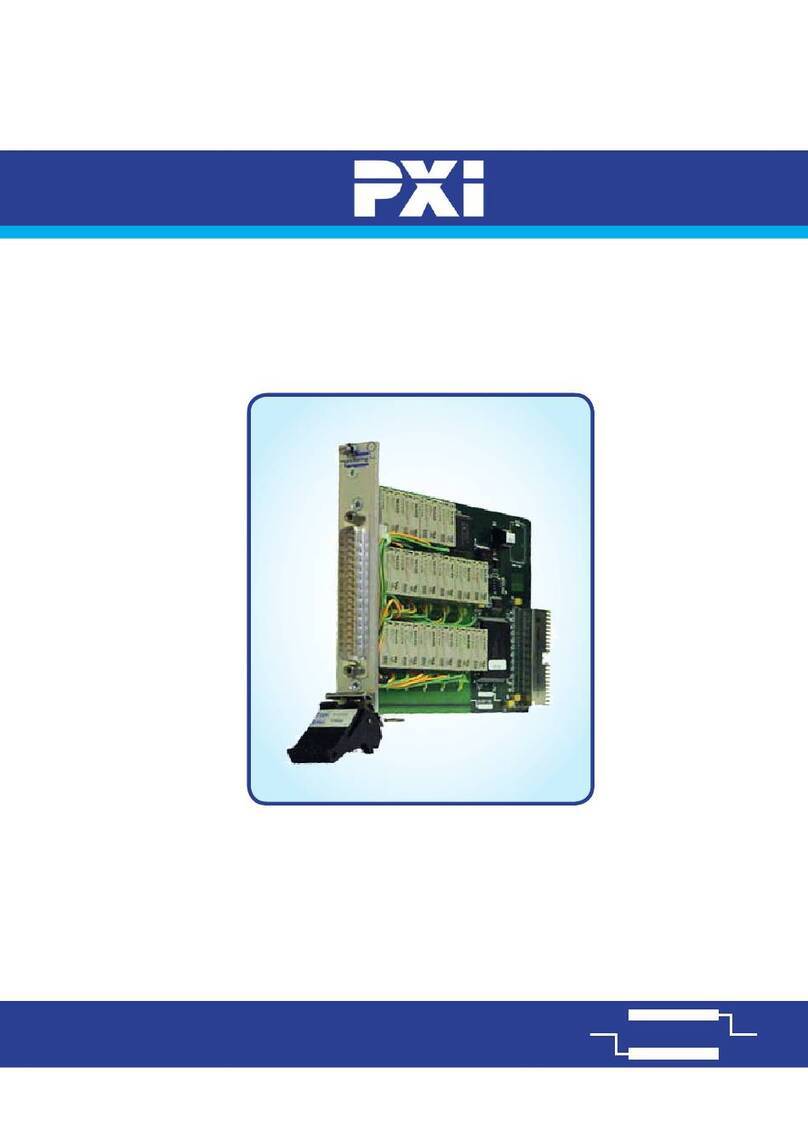
SecureVision FD 4201 User manual

Extension Module FD4201 Extension Module FD4201
Instruction Manual Page4
Revision 03.10 of 4 Instruction Manual Page1
Revision 03.10 of 4
Extension Module
- The fire control panel enters Fire condition and the relay,
corresponding to the chosen line, is activated (example: Rel1 – for line
1);
Type FD 4201
Instruction Manual 03.10
- If the relay is configured with normally open contact, then in Fire
condition it is closed; General Description
Module FD 4201 expands the options of fire control panel FS4000.
- Press button to reset the fire control panel. The relay (e.g.: Rel1)
should be reset to its initial position;
It allows:
- Connection of fire control panel FS4000 in a system of a repeater
FS5200R and/or several remote fire control panels FS4000, FS5100,
FS5200, FS5200E;
- If no other relay of another line is going to be tested, reset the delay of
the fire control panel to its initial settings (0, 1, 2, 3, 4 or 5 minutes). - Commanding the fire control panel from the repeater within a network of
remote fire control panels
ATTENTION! The relays of Extension Module do not commutate 220V! - Control of a relay output for each line that is in Fire condition.
The module could work only with the latest version of the fire control panel
FS4000 (fire control panels with serial numbers after 4000). It is manufactured in 4
variants corresponding to the nomenclature of the produced fire control panels
FS4000, with 2, 4, 6 or 8 lines, respectively with 2, 4, 6 or 8 relay outputs.
2. Testing the interface part
The interface part RS485 of the Extension Module FD 4201 is tested as a
part of a network consisting of repeater FS5200R and remote fire control
panels. The parameters of the repeater have to be defined correctly for
realization of the connection. The network address and the data exchange
speed along RS485 in a fire control panel, equipped with an extension module
are fixed:
Interface RS485 is an integral part of the module and it is offered in all variants.
The module includes:
- Interface RS485 for connection with repeater FS5200R;
- Potential free relays for Fire condition (one to each line of the fire control
panel FS4000).
- The fire control panel network address coincides with its serial number;
- the data exchange speed is fixed – 9600 bits/s. The unit
consists of an
installation base, PC
board and ribbon
cable.
Complete set
Installation
base
Relays, adivated in Fire condition
Terminals for connecting
RS485 to the network
Ribbon cable
Coupling for connection with the
fire control panel FS4000
PC Board Extension Module - 1 pc.
Ribbon cable - 1 pc.
Instruction manual - 1 pc.
Package - 1 pc.
Technical service
It should be done only by an authorized person as it includes the actions
for the technical service of the fire control panel.
Fig.1
Warranty
The warranty period is 18 months from the date of sale. The communication between the fire control panel and the extension module
FD 4201 is executed via a ribbon cable, connecting the fire control panel and the
unit. The module is power supplied along the ribbon cable.
Technical Data
Relay outputs for Fire condition
- type potential free, switching
- power supply 3A/125VAC; 3A/30VDC
Interface RS485
- network address fixed – coincides with the serial number of the fire
control panel
- data exchange speed fixed – 9600 bits/s.
Operational temperature range from минус 5оСto 40оС
Relative humidity resistance max 93% at 40оС
The manufacturer guarantees the normal performance of the unit providing
that the operation requirements set herewith have been observed.
The manufacturer
does
not
bear
warranty
liabilities
for
damages
caused
through
accidental mechanical
damage,
misuse,
adaptation
or
modification
after
production.
The
manufacturer bears
warranty
liabilities
for
damages
in
the
unit
caused
through
manufacturer's
fault
only.
Dimensions 180 х65 х25 mm
Weight 0,160 kg

Extension Module FD4201 Extension Module FD4201
Instruction Manual Page2
Revision 03.10 of 4 Instruction Manual Page3
Revision 03.10 of 4
6
Installation
Install the unit by observing the following sequence:
1. Preparation of the Extension Module for installation:
1.1. Unpack the module.
1.2. Configure the jumpers of the relay contacts by means of pincers (normal
open or normal close) depending on the specific project, pos. 4 (fig. 2).
1.3. Shunt the interface RS485 line (see Instruction Manual of Fire Control
Panel FS4000):
- if the connected fire
control panel is the first or
the last one in the created
local network, switch the
jumper in the module,
pos. 1 (fig. 2). The
module is delivered with
switched terminating
jumper;
- if the fire control panel is
not final one (first or last)
– the jumper is switched
off.
1 4
2 3
Fig.2
2. Installation of Extension Module FD 4201 in fire control panel FS4000
2.1. Open the front cover of the fire control panel.
2.2. Remove fuse Fu1 from the jack, pos. 1 (fig. 3).
2.3. Disconnect the wires from the terminals of the backup batteries, pos.2
(fig.3).
2.4. Unscrew both screws, pos.3 (fig.3).
2.5. Place the module as it is shown on fig. 4 and fixed it by means of both
screws, pos. 3 (fig.3).
2.7. Connect the ribbon cable to the module, pos. 4 (fig.3) and to the coupling
of the fire control panel, pos. 5 (fig.3). The couplings are provided with a slot,
determining the direction of the connection.
4
1
2
3
5
Fig.3
3. Connecting the interface and the commutated output devices
3.1. Pass the connecting wires of the local network and the monitored devices
through the respective holes in the fire control panel box.
3.2. The wires of the local network are connected to terminals “А” and “В” of the
extension module, pos. 2 (fig. 2).
3.3. Connect the circuits of the monitored devices to the fire condition relays,
pos. 3 (fig. 2), according to the specific project.
4. Switching the fire control panel with installed module FD 4201
4.1. Place the mains fuse of the fire control panel Fu1 in its jack, pos. 1 (fig. 3).
4.2. Connect the backup battery power supply, pos.2 (fig.3). The fire control
panel enters Duty Mode.
4.3. Close the front cover of the fire control panel.
The entered delay for the monitored outputs of the fire control panel
refers to the relays of Extension Module FD4201 too.
Testing
Extension Module FD 4201 is tested after installation as an element of the fire
control panel or after maintenance activities.
1. Testing of the relay part
Set delay of the outputs “0” minutes in the fire control panel by means of jumper
J1 (see Instruction Manual of Fire Control Panel FS4000);
- Simulate fire condition in a randomly chosen line (for example: line 1);
Popular Control Unit manuals by other brands
AVR
AVR 30 Series Installation, operation & maintenance manual
etp
etp HYDRO-GRIP GEW2 Assembly instructions
Camozzi
Camozzi K8 Series Use and maintenance instructions

Tyco Fire Product
Tyco Fire Product CB800 installation instructions
Sharp
Sharp PN-ZB03 Series installation manual
mikroElektronika
mikroElektronika nRF C Click manual

Crane
Crane D1088 Installation, operation and maintenance instructions
Alpha Technologies
Alpha Technologies Cordex 24 manual
Siemens
Siemens SINUMERIK 840D sl Function manual
CAMBRIONIX
CAMBRIONIX ModIT-MAX user manual

AMC
AMC AMC-1228 instructions

Singer Valve
Singer Valve 106-PG Installation, Operating and Maintenance Instruction
