Sloan G2 Optima Plus Operating manual
FOR USE WITH SLOAN’S ORIGINAL OPTIMA®PLUS
FLUSHOMETER PRODUCED FROM 1992 - 2003
AND REGAL PRO®OPTIMA PLUS PRODUCED AFTER MAY, 2003
LIMITED WARRANTY
Sloan Valve Company warrants its Flushometer Products to be made of first
class materials, free from defects of material or workmanship under normal
use and to perform the service for which they are intended in a thoroughly
reliable and efficient manner when properly installed and serviced, for a period
of three years (one year for special finishes) from date of purchase. During
this period, Sloan Valve Company will, at its option, repair or replace any part
or parts which prove to be thus defective if returned to Sloan Valve Company,
at customer’s cost, and this shall be the sole remedy available under this
warranty. No claims will be allowed for labor, transportation or other incidental
costs. This warranty extends only to persons or organizations who purchase
Sloan Valve Company’s products directly from Sloan Valve Company for
purpose of resale.
THERE ARE NO WARRANTIES WHICH EXTEND BEYOND THE DESCRIPTION
ON THE FACE HEREOF. IN NO EVENT IS SLOAN VALVE COMPANY
RESPONSIBLE FOR ANY CONSEQUENTIAL DAMAGES OF ANY MEASURE
WHATSOEVER.
Maintenance Guide •SENSOR OPERATED VALVES
OPTIMA PLUS M.G. – Rev. 2 (09/03) Code No. 0816193
The Sloan Valve Company introduced its OPTIMA Plus Battery Operated
Sensor Flushometer in 1992 revolutionizing the flushing of water closets
and urinals. In both new construction and retrofit applications the use of the
OPTIMA Plus has become the standard method for many facilities to
improve restroom hygiene and ensure handicap accessibility compliance.
In May, 2003 Sloan introduced the G2®OPTIMA Plus.
The G2 OPTIMA Plus builds on the success of the original product and
offers many technological advancements to further improve on
performance and reliability expected of sensor operated plumbing. In
addition to a new aesthetic design, the G2 OPTIMA Plus features a new
state-of-the-art electronic and optical package and a unique Solenoid
Operator that keeps the moving components of the Solenoid completely
isolated from the water supply. This ensures long life and low maintenance
regardless of local water conditions.
The G2 OPTIMA Plus replaces the original OPTIMA Plus product, which
was phased out of production in mid 2003. Regal Pro OPTIMA Plus Valves
produced after May, 2003 include G2 Interior Components with the old
style OPTIMA Plus Cover.
Many of the new technologies developed for the G2 have been integrated
into the repair parts available for the older OPTIMA Plus product. This
Maintenance & Repair Guide reflects these new components and includes
crossover information for the old components.
Use this Maintenance & Repair Guide for OPTIMA Plus Valves produced
from 1992 - 2003 and Regal Pro Optima Plus Valves produced after
May, 2003 only.
For the G2 OPTIMA Plus, use Maintenance & Repair Guide #0816456.
If further assistance is required, please contact the Sloan Valve Company
Installation Engineering Department at:
Phone: 1-888-SLOAN-14 (1-888-756-2614)
Email: productsuppor[email protected]
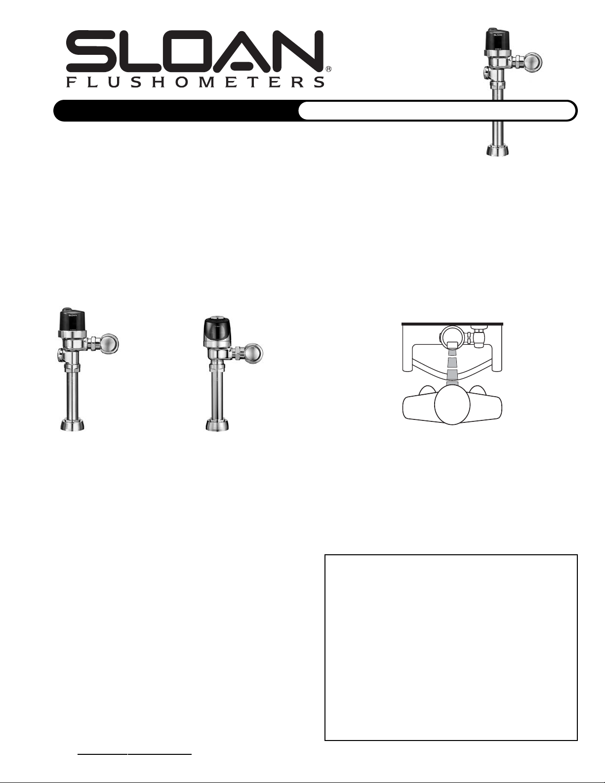
The Sloan OPTIMA Plus automatic battery powered Flushometer relies on
an infrared sensor to detect a user and activate a flushing cycle. No
physical contact with the Flushometer surface is necessary, assuring
sanitary protection. OPTIMA Plus Flushometers are ADA compliant devices
and are available in both Royal®and Regal®Flushometer models.
The Flushometer is triggered by means of an active infrared Sensor. The
OPTIMA Plus Sensor emits a continuous invisible light beam. When a user
enters the beam’s effective range, the beam is reflected into the OPTIMA
Plus Scanner Window. The user is now detected. After the user moves out
of the effective range of the Sensor, a signal is sent to the Flushometer
Solenoid and, after appropriate arming and/or flush delays, the flush cycle
is initiated.
G2®OPTIMA PLUS
FLUSHOMETER
ORIGINAL
OPTIMA PLUS
FLUSHOMETER
AND REGAL PRO®
OPTIMA PLUS
2
SENSOR OPERATED FLUSHOMETERS
For all Optima Plus produced from 1992 - 2003
And Regal Pro Optima Plus produced after May, 2003
3
8
7
2C
2D
1
2B
2A
4
5
6
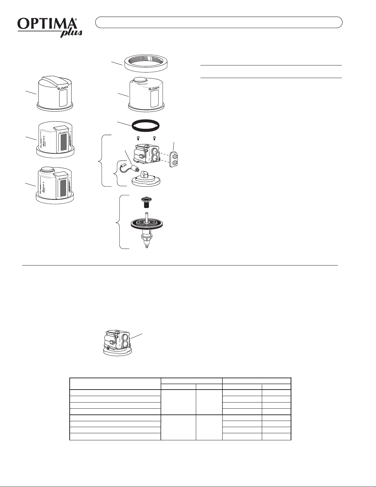
SENSOR MODULE COMPONENT PARTS
Item Code Part
No. No. No. Description
1. 0325804 EBV-14 Locking Ring
3325524 EBV-31-A Locking Ring for Zurn Valve Bodies
2A. 0325806 EBV-11 Cover (Urinal)
2B. 3325538 EBV-38-A Cover w/Override Button (Water Closet)
2C.3325012 EBV-55-A Metal Cover Assembly (Urinal)
3325017 EBV-1034-A Metal Cover Assembly for Zurn Valve
Body (Urinal)
2D. 3325013 EBV-60-A Metal Cover Assembly with
Override Button (Water Closet)
3325016 EBV-1033-A Metal Cover Assembly w/Override Button
for Zurn Valve Body (Water Closet)
3. 5325011 EBV-67 Cover Gasket — 12 per package
4. SEE CHART BELOW — ELECTRONIC MODULE
5. 0325814 EBV-21-A Inside Cover Assembly
(Includes Solenoid)
6. 3325462 EBV-144-A Isolated Solenoid Operator †
7. SEE CHART on PAGE 3 — Flex Tube Diaphragm Kit
8. 3325537 EBV-46-A Beam Deflector ‡
† The new EBV-144-A Isolated Solenoid replaces the Solenoid used with
the old style Black EBV-26-A Modules only.
For Blue EBV-146-A G2 Modules, use the EBV-136-A (code #3325453)
Isolated Solenoid Operator.
Refer to Page 4 for instructions regarding Solenoid replacement.
‡ Beam deflectors are for use on Black, old style Modules. They are not
required (and will not work) on Blue G2 Modules.
ELECTRONIC MODULE ASSEMBLY CHART
The electronic and optical improvements of the G2 OPTIMA Plus have been
incorporated into the Electronic Modules for use with older OPTIMA Plus
products.
ELECTRONIC
SENSOR
MODULE
There are now only two Electronic Module Assembly variations for
use with older OPTIMA Plus valves:
• EBV-146-A-U Urinal
• EBV-146-A-C Water Closet
This chart cross references the part numbers and code numbers of
our new Electronic Modules over from our old Module numbers.
The EBV-146-A Modules include the Isolated Solenoid, Inner Cover
and Electronic Module.
These Modules are for use with older OPTIMA Plus and Regal Pro
OPTIMA Plus Valves only. Consult Maintenance & Repair Guide
#0816456 for G2 OPTIMA Plus Electronic Modules.
USE TO RREPLACE
New PPart NNo. Code NNo. Old PPart NNo. Code NNo.
Electronic Module — 0.5 gpf/1.9 Lpf Urinal EBV-26-A-U-0.5 3325039
Electronic Module — 1.0 gpf/3.8 Lpf Urinal EBV-26-A-U-1.0 3325540
Electronic Module — 1.5 gpf/5.7 Lpf Urinal EBV-26-A-U-1.5 3325541
Electronic Module — 3.5 gpf/13.2 Lpf Urinal EBV-26-A-U-3.5 3325543
Electronic Module — 1.6 gpf/6.0 Lpf Closet EBV-26-A-C-1.6 3325542
Electronic Module — 2.4 gpf/9.0 Lpf Closet EBV-26-A-C-2.4 3325643
Electronic Module — 3.5 gpf/13.2 Lpf Closet EBV-26-A-C-3.5 3325544
Electronic Module — 4.5 gpf/17.0 Lpf Closet EBV-26-A-C-4.5 3325545
Optima Plus Modules can be identified
by color.
Old style Modules are Black and have a
wire that runs along the side of the unit.
G2 Modules are Blue and have a wire
only on the back of the unit.
Description
Note: EBV-26-A Modules are no longer available. Use the EBV-146-A Module shown.
EBV-146-A-U 0325177
EBV-146-A-C 0325176

3
SENSOR OPERATED FLUSHOMETERS
DIAPHRAGM INSIDE PARTS KITS
FLEX TUBE DIAPHRAGM ASSEMBLY
In early 2003 Sloan introduced the Flex Tube Diaphragm kit into the OPTIMA
Plus. This design completely replaced the old OPTIMA Plus Diaphragm Kit
that featured the metal shaft with the Quad Ring. This change further
improved the reliability of the OPTIMA Plus as it replaced a wearable
dynamic seal (the Quad Ring) with a non-moving static O-ring seal.
The Flex Tube Diaphragm Kit also features Sloan's exclusive Dual Filter
Diaphragm. The Dual Filter Diaphragm helps to protect the valve from water
bourn sediment that can cause the valve to stick open and run on. The Dual
Filter diaphragm is also made from Sloan's Permex Synthetic Rubber
material for resistance against chloramines and other water treatment
chemicals.
FLEX TUBE DIAPHRAGM KITS
5325056 EBV-83 O-ring — 6 per package
REGULATORS
The flush volume of the Flex Tube
Diaphragm Kit is control by the
Regulator. Regulators are identified
by color. Some Flex Tube Diaphragm
Kits are supplied with multiple
Regulators. The installer must make
sure the proper regulator is used
when installing the Flex Tube
Diaphragm Kit.
OLD STYLE DIAPHRAGM INSIDE PARTS
The EBF-18 Quad Ring is still available.
5325813 EBV-18 Quad Ring — 12 per package
† The EBV-1020-A and EBV-1022-A Kits are supplied with multiple Regulators.
‡ A 0.5 gpf (1.9 Lpf) Urinal kit can be converted to a 1.0 gpf (3.8 Lpf) by cutting and removing
the smooth A-164 Flow Ring from the Guide.
§ For a 4.5 gpf (17.0 Lpf) Water Closet flush, use the EBV-1020-A Kit with the White Regulator,
and cut and remove the A-164 Flow Ring from the Guide.
Color of Regulator to be used with Flex Tube Diaphragm to obtain the listed flush volume.
KIT NO. COLORCODE NO. KIT NO. CODE NO.
URINAL-0.5 gpf/1.9 Lpf EBV-1023-A GREEN 3325003 EBV-32-A-U-0.5 3325038
URINAL-1.0 gpf/3.8 Lpf ‡ EBV-1022-A GREEN 3325000 EBV-32-A-U-1.0 3325851
URINAL-1.5 gpf/5.7 Lpf EBV-1022-A BLACK 3325000 EBV-32-A-U-1.5 3325818
URINAL-3.5 gpf/13.2 Lpf EBV-1020-A WHITE 3325001 EBV-10-A-U-3.5 3325841
CLOSET-1.6 gpf/6.0 Lpf EBV-1020-A GREEN 3325001 EBV-10-A-C-1.6 3325850
CLOSET-2.4 gpf/9.0 Lpf EBV-1021-A BLUE 3325014 EBV-10-A-C-2.4 3325033
CLOSET-3.5 gpf/13.2 Lpf EBV-1020-A WHITE 3325001 EBV-10-A-C-3.5 3325841
CLOSET-4.5 gpf/17.0 Lpf § EBV-1020-A WHITE 3325001 EBV-10-A-C-4.5 3325842
REGULATOR (Sold 6 per package)
The EBV-1020-A and EBV-1022-A Kits are supplied with multiple Flush Volume Regulators. The
Installer must use the correct Regulator when installing the kit.
ADJUSTING THE OLD STYLE INSIDE DIAPHRAGM ASSEMBLY
The Inside Diaphragm Assembly was set at the factory to ensure an
accurate flush cycle over a range of water pressures.
If adjustment is required, remove the Inside Diaphragm Assembly and turn
it upside down. Inside the Assembly Guide is an Adjustment Screw. Insert
a slotted screwdriver and turn the Adjustment Screw according to the
Conversion Guidelines.
Turning the Adjustment Screw
clockwise DECREASES the flush
volume.
Turning the Adjustment Screw
counterclockwise INCREASES
the flush volume.
For full adjustment procedures,
see OPTIMA Plus Conversion
Guide #0816511.
FLUSH VOLUME REGULATOR PART CODE
AND FIXTURE COLOR NO. NO
URINAL-0.5 gpf/1.9 Lpf GREEN EBV-95 5325122
URINAL-1.0 gpf/3.8 Lpf GREEN EBV-95 5325122
URINAL-1.5 gpf/5.7 Lpf BLACK EBV-102-2 5325129
URINAL-3.5 gpf/13.2 Lpf WHITE EBV-102-1 5325130
CLOSET-1.6 gpf/6.0 Lpf GREEN EBV-95 5325122
CLOSET-3.5 gpf/13.2 Lpf WHITE EBV-102-1 5325130
CLOSET-2.4 gpf/9.0 Lpf BLUE EBV-101 5325128
QUAD RING
FLEX TUBE
DIAPHRAGM
KIT
REGULATOR
FLEX TUBE DIAPHRAGM
The Flex Tube Diaphragm can be used to replace all generations of Sloan
OPTIMA Plus Diaphragm Kits. The same Flex Tube Diaphragm kits are used
in the G2 OPTIMA Plus valve.
FLEX TUBE DIAPHRAGM INSIDE
PARTS KIT (INTRODUCED FEB., 2003)
O-RING (Part # EBV-83)
OLD STYLE KITS ARE
OBSOLETE. SEE CHART
FOR REPLACEMENT.
USE TO RREPLACE
0-RING
REGULATOR
(MUST BE INSTALLED
PAST 0-RING)
FLEX TUBE
DIAPHRAGM
FLEX TTUBE DIAPHRAGM KKIT WW/
DIAPHRAGM KKIT ††QUAD RRING ((OBSOLETE)
APPLICATION
4
SENSOR OPERATED FLUSHOMETERS
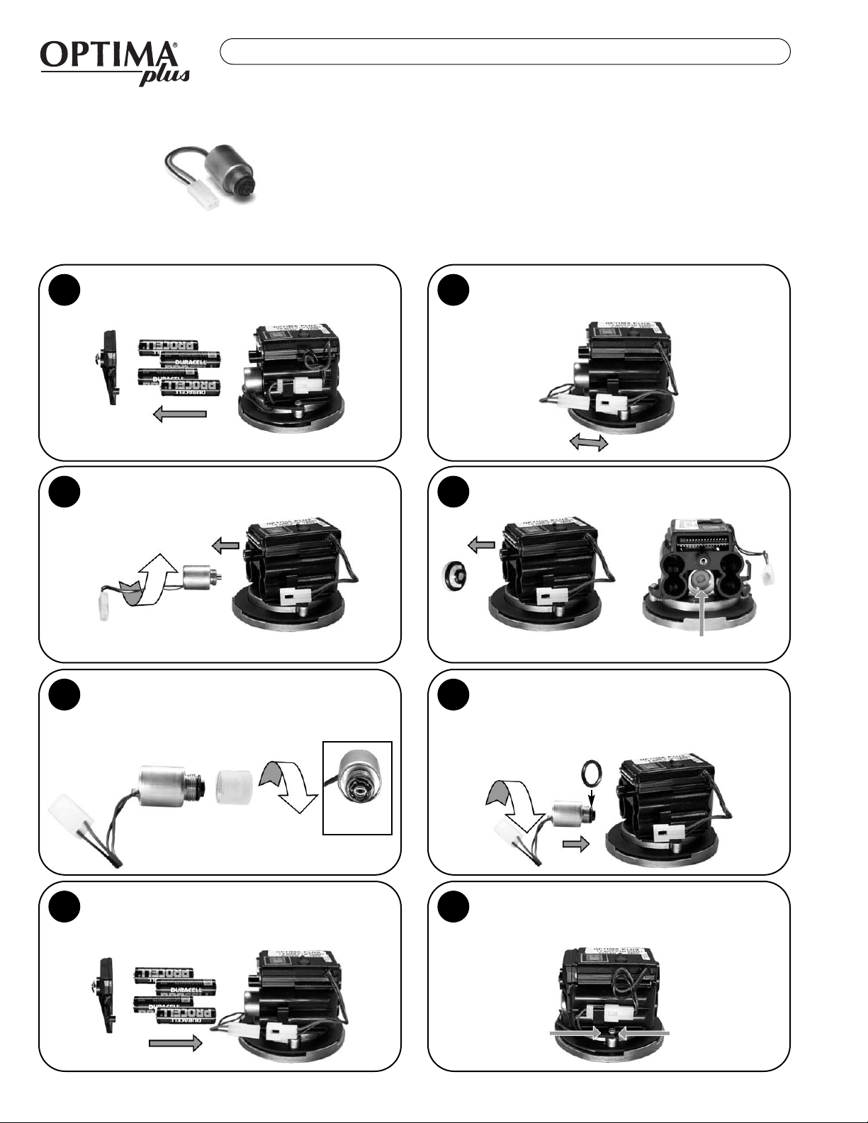
Remove Battery Cover and Batteries from existing
Sensor Module.
12
Unscrew (counterclockwise) the existing
Solenoid Valve from the Base Plate.
3Remove White Plastic Seat and O-rings that are
located inside the Housing.
4
Back View
Remove Clear Plastic Housing from the threaded
end of new Isolated Operator by unscrewing
(counterclockwise). It is normal to find water
inside this housing.
56
Reconnect the White Plastic Connectors on the
side of the Module. Slide the White Connector
into the Clip to secure. Tuck Wiring in close to
Module.
8
Reinstall batteries in the correct position and
reattach Battery Door.
7
Front View
Make sure O-ring is installed on the Black
Housing of the new Isolated Operator. Install
Isolated Operator by threading it (clockwise) into
the Housing. Tighten with fingers beyond just
snug.
For use with Black Optima Plus EBV-26-A Modules only (produced 1992-2003)
For G2 Optima Plus Modules (identified by a Blue Module) use the EBV-136-A Solenoid
Disconnect the White Plastic Connector that
connects the Black and Red Wires on the side of
the Module.
EEBBVV--114444--AACCOODDEE##33332255446622
IISSOOLLAATTEEDDSSOOLLEENNOOIIDDOOPPEERRAATTOORR
SOLENOID REPLACEMENT
5
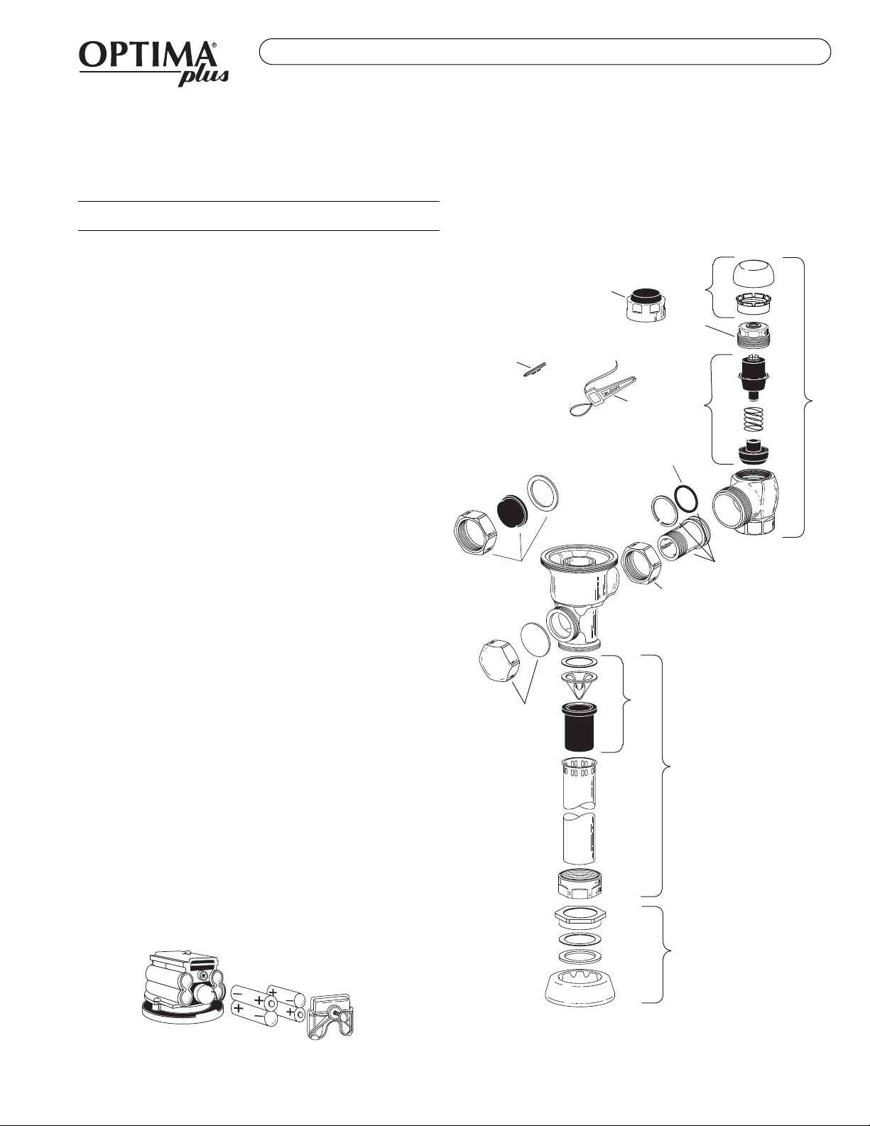
OTHER VALVE COMPONENT PARTS
Item Code Part
No. No. No. Description
9. 3325814 EBV-1017-A Handle Cap — Metal
10. 3325815 EBV-1018-A Handle Cap — Decorative
11. 3323182 V-651-A Vacuum Breaker Repair Kit
12. 0393004 V-600-A ¾'' (19 mm) x 9'' (229 mm) CP Vacuum Breaker
0393006 V-600-A 1¼'' (32 mm) x 9'' (229 mm) CP Vacuum
Breaker
0393007 V-600-A 1½'' (38 mm) x 9'' (229 mm) CP Vacuum
Breaker
13. 0306125 F-5-A ¾'' (19 mm) CP Spud Coupling
0306140 F-5-A 1¼'' (32 mm) CP Spud Coupling
0306146 F-5-A 1½'' (38 mm) CP Spud Coupling
14. 0308676 H-550 CP Stop Coupling
15. 0308801 H-551-A CP Adjustable Tailpiece 2-1/16'' (52 mm) long
16. 5308696 H-553 O-ring — 24 per package
17. 3308386 H-700-A 1'' (25 mm) Screwdriver Bak-Chek®Stop CP —
complete
3308384 H-700-A ¾'' (19 mm) Screwdriver Bak-Chek®Stop CP —
complete
18. 3308853 H-541-A Control Stop Repair Kit †
3308856 H-543-A Control Stop Repair Kit ‡
19. 0308612 H-622 CP Bonnet †
0308843 H-577 CP Bonnet ‡
20. 3308791 H-1010-A Vandal Resistant Control Stop Cap Assembly †
3308790 H-1009-A Vandal Resistant Control Stop Cap Assembly ‡
21. 3325816 EBV-1019-A ¾'' (19 mm) Decorative Stop Cap
3308866 H-574 1'' (25 mm) Decorative Stop Cap
Accessories
22. 0325107 EBV-91 Trimpot Adjustment Screwdriver
23. 0325823 EBV-22 Disposable Strap Wrench
† For use w/H-700-A 1'' & ¾'' and H-600-A 1'' Screwdriver Bak-Chek®Control Stops.
‡ For use w/H-600-A ¾'' Screwdriver Bak-Chek®Control Stops.
18 17
21
16
20
19
15
14
10
9
12
11
13
SENSOR OPERATED FLUSHOMETERS
Battery Replacement
When OPTIMA Plus has approximately 4,000 flushes left, the same red
light that appears at start-up will flash four (4) times quickly whenever an
object is detected. When this occurs, we recommend changing the
batteries.
Separate Locking Ring, Cover and Flex Tube Diaphragm from Electronic
Sensor Module.
Loosen Retaining Screw on Battery Compartment Door and remove Battery
Compartment Door. Install four (4) Alkaline, AA Batteries exactly as
illustrated. Install Battery Compartment Door and secure with Retaining
Screw. Make certain that Battery Compartment Door is fully compressed
against Gasket to provide a seal; Do Not overtighten.
For all Optima Plus produced from 1992 - 2003
And Regal Pro Optima Plus produced after May, 2003
22
23
II..SSeennssoorrFFllaasshheessCCoonnttiinnuuoouussllyyOOnnllyyWWhheennUUsseerrSStteeppssWWiitthhiinnRRaannggee..
A. Unit in Start-Up mode; no problem. This feature is active for the first 10
minutes of operation.
IIII..VVaallvveeDDooeessNNoottFFlluusshh;;SSeennssoorrNNoottPPiicckkiinnggUUppUUsseerr..
A. Range too short; increase the range.
B. OPTIMA Plus installed on a high rough-in fixture (beam is shooting over
the user's head). Install the Sloan EBV-46-A Beam Deflector (black
modules only).
IIIIII..VVaallvveeDDooeessNNoottFFlluusshh;;SSeennssoorrPPiicckkiinnggUUppOOppppoossiitteeWWaalllloorrSSuurrffaaccee,,oorr
OOnnllyyFFlluusshheessWWhheennSSoommeeoonneeWWaallkkssBByy..RReeddLLiigghhttFFllaasshheess
CCoonnttiinnuuoouussllyyffoorrFFiirrsstt1100MMiinnuutteessEEvveennwwiitthhNNooOOnneeiinnFFrroonnttoofftthhee
SSeennssoorr..
A. Range too long; shorten range.
B. Sensor is picking up mirror or highly reflective wall or surface in front of
fixture. Install OPTIMA Plus slightly "off-center" (2 to 5 degrees) to
eliminate direct reflection off of mirror or opposite wall or surface.
IIVV..VVaallvveeDDooeessNNoottFFlluusshhEEvveennAAfftteerrAAddjjuussttmmeenntt..
A. Range Adjustment Potentiometer set at full "max" or full "min" setting.
Readjust Potentiometer away from full "max" or "min" setting.
B. Batteries completely used up; replace batteries.
C. Problem with Electronic Sensor Module; replace Electronic Sensor
Module.
VV..UUnniittFFllaasshheess44QQuuiicckkTTiimmeessWWhheennUUsseerrSStteeppssWWiitthhiinnRRaannggee..
A. Batteries low; replace batteries.
VVII..VVaallvveeDDooeessNNoottSShhuuttooffff..
A. Bypass orifice in diaphragm is clogged with dirt or debris, or bypass is
clogged by an invisible gelatinous film due to "over-treated" water.
Remove Flex Tube Diaphragm and wash under running water.
Note: Size of orifice in the Bypass is of utmost importance for the proper
metering of water by the valve. DO NNOT EENLARGE OORDDAMAGE TTHIS
ORIFICE. Replace Flex Tube Diaphragm if cleaning does not correct the
problem.
B. Dirt or debris fouling Stem or Flex Tube Diaphragm. Remove Flex Tube
Diaphragm and wash under running water.
C. Problem with Solenoid. If cleaning does not correct the problem, replace
with new Isolated Solenoid Operator.
VVIIII..NNoottEEnnoouugghhWWaatteerrttooFFiixxttuurree..
A. Wrong OPTIMA Plus Flex Tube Diaphragm installed; i.e., 1.0 gpf urinal
installed on 3.5 gpf closet fixture. Replace with proper Diaphragm
Assembly.
B. Enlarged Bypass in Diaphragm. Replace with Flex Tube Diaphragm Kit.
C. Control Stop not adjusted properly. Readjust Control Stop.
D. Inadequate volume or pressure at supply. Increase water pressure or
supply (flow) to valve. Consult factory for assistance.
VVIIIIII..TTooooMMuucchhWWaatteerrttooFFiixxttuurree..
A. Control Stop not adjusted properly. Readjust Control Stop.
B. Wrong OPTIMA Plus Flex Tube Diaphragm installed; i.e., 3.0 gpf model
installed on 1.0 or 1.5 gpf urinal fixture. Replace with proper OPTIMA Plus
Diaphragm Assembly.
C. Dirt in Diaphragm Bypass. Clean under running water or replace with new
Flex Tube Diaphragm.
IIXX..MMeenn''ssRRoooommCClloosseettBBoowwllssUUnnfflluusshheedd..
A. Closet being used as urinal. Angle Sensor slightly off fixture centerline to
detect standing person in front of fixture.
XX..HHiigghhVVaaccuuuummBBrreeaakkeerrIInnssttaallllaattiioonn
((MMooddeell88111155//88111166))——UUnniittNNoottFFlluusshhiinngg..
A. EBV-46-A Beam Deflector not installed. Install EBV-46-A Beam Deflector
(black modules only) to divert Sensor beams.
XXII..EElleemmeennttaarryySScchhoooollUUrriinnaallssNNoottFFlluusshhiinngg..
A. Unusually short users not being detected. Install EBV-46-A Beam
Deflector (black modules only) to divert Sensor beams.
† Note: Use on Black Modules Only.
BATTERIES
When required, replace batteries with four (4) Alkaline Type AA batteries.
For information and instructions on field converting OPTIMA Plus Module
settings or to activate the Stadium Flush™ Feature in urinal models, see the
Sloan OPTIMA Plus Conversion Guide (0816511).
This manual and the OPTIMA Plus Repair and Maintenance Guide are
available at www.sloanvalve.com
CARE AND CLEANING OF CHROME AND SPECIAL FINISHES
DO NOT use abrasive or chemical cleaners to clean Flushometers as they
may dull the luster and attack the chrome or special decorative finishes.
Use ONLY soap and water, then wipe dry with clean cloth or towel.
While cleaning the bathroom tile, the Flushometer should be protected from
any splattering of cleaner. Acids and cleaning fluids can discolor or remove
chrome plating.
Refer to the OPTIMA Plus Flushometer Maintenance Guide for additional
Troubleshooting and Repair Part information.
If further assistance is required, please contact the Sloan Valve
Company Installation Engineering Department at 1-888-SLOAN-14
(1-888-756-2614).
Manufactured in the U.S.A. by Sloan Valve Company under one or more
of the following patents: U.S. Patents: 4,893,039; 5,169,118; 5,244,179;
5,295,655; Des. 345,113; Des. 355,478. Other Patents Pending. BAK-
CHEK®, PARA-FLO®, PERMEX®, TURBO-FLO®.
Troubleshooting and Maintaining the Sloan OPTIMA Plus Flushometer
SLOAN VALVE COMPANY • 10500 SEYMOUR AVENUE • FRANKLIN PARK, IL 60131
Phone: 1-800-9-VALVE-9 or 1-847-671-4300 • Fax: 1-800-447-8329 or 1-847-671-4380 • www.sloanvalve.com
Copyright © 2003 Sloan Valve Company Printed in the U.S.A. Made in the U.S.A. OPTIMA PLUS M.G. — Rev. 2 (09/03) Code No. 0816193
SENSOR OPERATED FLUSHOMETERS
FOR USE WITH SLOAN’S ORIGINAL OPTIMA PLUS
FLUSHOMETER PRODUCED FROM 1992 - 2003
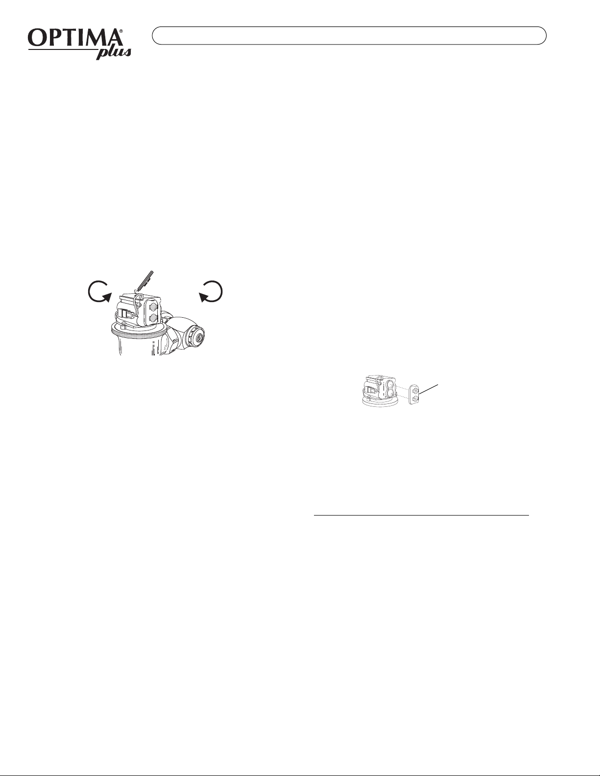
COUNTERCLOCKWISE CLOCKWISE
Decreases
Range Increases
Range
EBV-46-A BEAM
DEFLECTOR †
Other manuals for G2 Optima Plus
6
This manual suits for next models
2
Table of contents
Other Sloan Control Unit manuals

Sloan
Sloan SOLIS 8100 Series User manual

Sloan
Sloan NAVAL 110 User manual

Sloan
Sloan Optima ETF-80 User manual

Sloan
Sloan 152 ES-S TMO SWB User manual

Sloan
Sloan 152 ES-S TMO SWB User manual

Sloan
Sloan Optima Plus EBV-500-A User manual

Sloan
Sloan G2 Optima Plus Operating manual

Sloan
Sloan TRUFLUSH TRF 8900-CP User manual


