Securiton SecuriFire 500 User guide

System description
SecuriFire 500 fire detection system

The SecuriFire system family
2 / 18 SecuriFire 500, System Description, T 811 058 en
Table of contents
1The SecuriFire system family 3
2The system concept 4
2.1 SecuriLan 5
2.2 SecuriFire FCP 500 5
2.3 Key features at a glance 6
3Display, operation and indication 7
3.1 SecuriFire MIC indication and control maps 7
3.2 External device bus 8
3.2.1 EPI-BUS 8
3.2.1.1 B5-EPI-PIM LED display panel 8
3.2.1.2 B5-EPI-PCM Partial indication and control map 9
3.2.1.3 B5-EPI-FPC Swiss fire brigade panel 9
3.2.1.4 B5-EPI-ASP Fire Brigade Panel for the Netherlands 9
3.2.1.5 B5-EPI-FAT Fire brigade indicator board according with DIN 14662 9
3.2.1.6 B5-EPI-FPD Fire brigade control board accroding with DIN 14661 9
3.2.1.7 B5-EPI-FPCZ Fire brigade panel for the Czech Republic 10
3.2.1.8 B5-EPI-FPS-S Fire Brigade Panel for Sweden 10
4Housing variants and expansion options 11
4.1 Housing variant 11
4.2 Modules 11
4.3 Mains connection and emergency power supply 11
5SecuriLine eXtended 12
5.1 Key features at a glance 13
5.2 System limits 13
6Components of the SecuriLine eXtended 14
7Programming and software 17
7.1 Projection 17
7.2 Loop configuration 17
7.3 Object texts 17
7.4 Download / Upload 17
8Service Tools 18
8.1.1 ServiceMonitor 18
8.1.2 ServiceCenter 18
8.1.3 SystemInformation 18
8.1.4 LoopAnalysis 18
8.1.5 Virtual MIC 18
9List of figures 19

The SecuriFire system family
SecuriFire 500, System Description, T 811 058 en 3 / 18
1 The SecuriFire system family
The SecuriFire system family consists of various control panels, devices, map case variants and components which can be
combined and coordinated perfectly for any configuration level and system size.
All devices are compatible with each other, work with the same software and the same commissioning tools. The user inter-
face is also identical for all SecuriFire devices.
Thanks to modular design and networking options, the required devices can be combined in any variation and adapted pre-
cisely to the system-specific requirements.
Fig.1
SecuriFire FCP 500
SecuriFire FCP 500 fire alarm control panel
•Compact one-loop system control panel
•For the connection of up to 250 elements
•Integrated IP interface
•Intuitive operation thanks to integrated SecuriFire MIC

The system concept
4 / 18 SecuriFire 500, System Description, T 811 058 en
2 The system concept
SecuriFire FCP 500 fire alarm control panel
SecuriFire 500 is a stand-alone fire alarm control panel and is suitable for connecting a SecuriLine eXtended addressable loop
with up to 250 participants. The control panel is equipped with all the necessary interfaces for connection to the fire brigade. It
also has relay outputs and a connection for the external device bus. The multilingual MIC11 operating panel is integrated di-
rectly in the door of the control panel.
Secured data transmission
Securiton's development engineers paid particular attention to ensuring secure data communication. Due to increasing envi-
ronmental and electromagnetic influences on control panels, detectors, peripheral devices as well as on the line network, a
digital data protocol with fault-detecting redundant coding was specially developed for fire alarm control panels.
The continuous, intelligent communication of peripheral elements and subsystems is assured maximum data security (ham-
ming code distance 4). This filters out false alarms caused by electromagnetic interference such as radio emissions, overvolt-
age, interference impulses etc.
All Securiton fire detection systems are equipped with automatic checking cycles, fault-detecting test routines, and measures
against electromagnetic interference. But with each new generation of performance features and operational reliability, key im-
provements have been achieved.
Overvoltage protection
The SecuriFire system is equipped with a comprehensive and integrated overvoltage
protection design which protects all peripheral inputs, including the mains power sup-
ply in compliance with EN 50130-4 (EMC) and EN 61000-6-2 (immunity for industrial
environments). The EMC protection concept protects the electronics by means of a
zone concept, Transzorp diodes, filters and broadband decoupling of the power sup-
ply.
Thus when the system is used in buildings with installed basic protection (lightning
protection, mains overvoltage arresters), no further measures are required (e.g. over-
voltage arresters).
Fig.2 Overvoltage protection

The system concept
SecuriFire 500, System Description, T 811 058 en 5 / 18
2.1 SecuriLan
The SecuriFire FCP 500 fire alarm control panel cannot be networked with other control units. Connection to superordinate
systems (e.g. management systems) and connection of the virtual MIC is possible with the integrated Ethernet interface.
Event memory
The default SecuriFire event memory is designed for 10000 messages.
LOCK OUTPUTS
The “LOCK OUTPUTS” function “freezes” all outputs in a defined state from a control panel by means of a software command
so that they are not unintentionally triggered.
This function saves considerable time and cost when service work and maintenance work are performed or when planning
software is downloaded.
Remote system diagnosis
Every SecuriFire FCP fire alarm control panel is pre-equipped for remote system diagnosis (remote polling) of system states
(e.g. detector soiling, faults).
Notice
The application remote system diagnosis of the SecuriFire 2000 fire alarm control panel is identical with the appli-
cation remote system diagnosis of the SecuriFire 3000 /2000 /1000 fire alarm control panel.
2.2 SecuriFire FCP 500
The fire detector system SecuriFire FCP 500 is a single loop fire alarm control panel for the smallest sized systems, suitable
for connecting a single loop circuit with a maximum of 250 devices.
The main processor unit contains all necessary interfaces for the connection to the fire brigade (transmission and alarm sys-
tems, interface for connecting various types of fire brigade control panels), as well as three 230V / 3A relay outputs and a con-
nection for the external device bus (EPI-BUS).
Features
•1 loop control unit
•Device bus for connecting remote indication and fire brigade maps.
•Interfaces for transmission and alarm systems, relay outputs, monitored inputs and outputs
•Simple to operate configuration and commissioning tools
•Event memory for 10,000 messages in real time
•Comprehensive, integrated overvoltage protection concept
Fig.3 Topology of a SecuriFire 500 fire alarm control panel

The system concept
6 / 18 SecuriFire 500, System Description, T 811 058 en
2.3 Key features at a glance
•Microprocessor controlled and monitored system technology.
•Continual, automatic check routines for all system components and programs.
•Main indication and control maps (MIC11)with graphic display; up to 4 languages can be toggled during operation.
•Suitable for connecting to the public alarm system of the fire brigade.
•Intervention switch for checking unwanted alarms.
•2-detector dependency and operational group dependency etc. freely programmable with software.
•Links and dependencies of fire incident controls and fire hatches freely programmable with software.
•Automatic winter time / summer time changeover.
•16 day/night levels with automatic on/off switching, date-based controls.
•Compliant with or exceeds the following relevant standards and directives: European standards EN 54, DIN, ÖNORM,
ÖVE, VDE, CPD and many more.
•VdS devices and system approval, CDP approval
Overview of system limits
Indication and control maps (internal)
max. 1
Fire brigade panels
max. 3
Inputs, outputs, repeat signals, Detection zones
max. 250
External (e.g. sprinkler systems)
max. 250
Delay layers
max. 16
Customer-specific texts
6,500 if average is 25 characters per element

Display, operation and indication
SecuriFire 500, System Description, T 811 058 en 7 / 18
3 Display, operation and indication
3.1 SecuriFire MIC indication and control maps
The SecuriFire standard indication and control maps provide well-organised, convenient, standards-compliant display and op-
eration of a SecuriFire system. In the SecuriFire FCP 500 the multilingual B7-MIC11 operating panel is integrated directly in
the door of the control panel.
Fig.4 SecuriFire FCP with built-in B7-MIC11 indication and control map
It includes a 5.7’’ TFT colour display for displaying all system states in plain text. No labelling on the front of the housing (only
display elements). Intuitive operation with operating elements and SecuriWheel.

Display, operation and indication
8 / 18 SecuriFire 500, System Description, T 811 058 en
3.2 External device bus
3.2.1 EPI-BUS
External devices and indication and control maps can be connected to the “EPI-BUS” on each MIC. A maximum of 3 partici-
pants can be connected to this data bus at a distance of up to 1 m from the main indication and control map (B7-MIC11).
Fig.5 Schematic of an EPI-BUS
EPI-BUS features
•MIC device bus
•Up to 1 m line length
•Up to 3 devices on one EPI-BUS
3.2.1.1 B5-EPI-PIM LED display panel
The B5-EPI-PIM is an LED display panel capable of accommodating labeling strips.
It is used for displaying functions, messages and states. The display uses 32 LEDs
(red and yellow; programmable) and has 1 green operation indicator. Insertion
stripes are used to label the LEDs.
Fig.6 B5-EPI-PIM

Display, operation and indication
SecuriFire 500, System Description, T 811 058 en 9 / 18
3.2.1.2 B5-EPI-PCM Partial indication and control map
The B5-EPI-PCM is an partial indication and control map capable of accommodating
labeling
strips. It is used for displaying functions, messages and states. The display
uses 16 LEDs (red and yellow, programmable). The eight function keys are freely
programmable. The EPI-PCM has also 1 green operation indicator. Insertion stripes
are used to label the buttons and LEDs.
Fig.7 B5-EPI-PCM
3.2.1.3 B5-EPI-FPC Swiss fire brigade panel
The B5-EPI-FPC is compliant with Swiss standard SN 054 002. In Switzerland it
must be mounted in the immediate vicinity of every fire alarm system in the fire bri-
gade access area. It displays certain operational states of the fire alarm systems
and enables fire brigade personnel to carry out essential procedures in a coordi-
nated and unified manner.
Fig.8 B5-EPI-FPC
3.2.1.4 B5-EPI-ASP Fire Brigade Panel for the Netherlands
The B5-EPI-ASP provides an easy man-machine-interface for the fire brigade. It can
be connected only to the MIC11 and MIC711.
Fig.9 B5-EPI-ASP
3.2.1.5 B5-EPI-FAT Fire brigade indicator board according with DIN 14662
The B5-EPI-FAT is compliant with the requirements of DIN 14662 for visually indi-
cat
ing the most important operating states of the fire alarm control panel to facilitate
easy and standardised operation of a fire alarm control panel for fire brigade per-
sonnel.
Fig.10 B5-EPI-FAT
3.2.1.6 B5-EPI-FPD Fire brigade control board according with DIN 14661
The B5-EPI-FPD is compliant with DIN 14661 for indicating operating states and for
standardised operation of a fire alarm control panel by fire brigade personnel.
Fig.11 B5-EPI-FPD

Display, operation and indication
10 / 18 SecuriFire 500, System Description, T 811 058 en
3.2.1.7 B5-EPI-FPCZ Fire brigade panel for the Czech Republic
The B5-EPI-FPCZ is compliant with the requirements of DIN 14662 for visually indi-
cating the most important operating states of the fire alarm control panel to facilitate
easy and standardised operation of a fire alarm control panel for fire brigade per-
sonnel. Display message and labels are in Czech language.
Fig.12 B5-EPI-FPCZ
3.2.1.8 B5-EPI-FPS-S Fire Brigade Panel for Sweden
The B5-EPI-FPS-S is compliant with SS3654. Displays the relevant operating states
to ensure simple operation by the fire brigade. Display message and labels are in
Swedish language.
Fig.13 B5-EPI-FPS-S

Housing variants and expansion options
SecuriFire 500, System Description, T 811 058 en 11 / 18
4 Housing variants and expansion options
4.1 Housing variant
•The basic configuration of every SecuriFire FCP 500 includes:
•Housing with integrated operating panel
•Rear wall with cut-outs for cable entry and battery holder
•Main control panel with interfaces for connecting operating panels, peripherals, service PC etc.
•Power supply unit
•2 batteries for emergency power supply
•
Mains terminals and battery cable
Fig.14
Basic circuit board with PSU and integrated MIC Fig.15
Housing with operating panel
4.2 Modules
B7-CPB11 main control unit
The B7-CPB11 is a component of every SecuriFire
FCP 500 fire alarm control panel and
contains all interfaces for connecting peripherals, relay contacts, and service PC.
No other units can be connected.
Fig.B7-CPB11
4.3 Mains connection and emergency power supply
The internal 75 W power supply unit delivers the output voltages of 3.3 V, 5 V and 27 V required in every SecuriFire FCP 500
control panel. On the bottom of the power supply unit is a 2-pin terminal for connecting the battery and a 2-pin plug-in screw
terminal to which external consumers can be connected. The power supply unit is equipped with battery monitoring which is
controlled and evaluated by the control panel's main control unit.
The emergency power batteries must be able to maintain the proper functioning of the fire alarm system for a certain length of
time in the event of a mains failure, and they must remain fully charged for their entire service life. Due to these high product
requirements, the charging and discharging characteristics of the batteries are subject to special requirements, specifications
and tests. Also, the charge curves of the batteries must exactly match the power supply unit in use.
The installation location for the batteries is on the housing base of each SecuriFire FCP. Two 7 Ah batteries connected in se-
ries are always used.

SecuriLine eXtended
12 / 18 SecuriFire 500, System Description, T 811 058 en
5 SecuriLine eXtended
The detectors and modules of the fire alarm system are connected to the ring-shaped installed SecuriLine eXtended from the
control panel. The SecuriLine eXtended is a 2-core field bus that guarantees the highest possible transmission reliability.
Fig.16 Schematic of SecuriLine eXtended ring circuit
Maximum transmission security
The continuous, intelligent communication between control panel and detectors (modules) is effected with maximum transmis-
sion security and enables seamless monitoring and evaluation of the current actual states. Faults in the line network or false
alarms due to electromagnetic interference (e.g. radio emissions, overvoltage, interference impulses) are automatically filtered
out and localised by data transmission with fault detecting redundant coding from the control panel.
Integrated short circuit isolator
Thanks to the short-circuit isolator integrated in each SecuriStar detector and in each ring circuit module, the SecuriLine eX-
tended remains fully functional even in the event of a fault. If a detector fails or in the event of a short-circuit or wire breakage
on the line, all other detectors and connected input and output modules remain functional without restriction. . The fault is lo-
calised and information about its exact position is shown in plain text on the display. This is why cable routing beyond fire sec-
tions can be optimised.
Intelligent data communication
Detector zone assignment for the SecuriLine eXtended is performed independently of the wiring, which is optimised and con-
siderably reduced. Inputs and outputs can be freely programmed without additional settings. Further, thanks to the microproc-
essor integrated in each detector, soiling detection, detector self-tests and detector analyses add to the performance spectrum
to prevent false alarms and reduce unwanted alarms.
Programming and commissioning
Programming and commissioning the SecuriLine eXtended is performed exclusively with the SecuriFire Studio software. A cal-
culation program is included for computing the maximum possible ring circuit length based on the connected elements and the
wire cross-section in use.

SecuriLine eXtended
SecuriFire 500, System Description, T 811 058 en 13 / 18
5.1 Key features at a glance
•Digital ring communication and data backup
•Monitoring of all connected detectors and modules
•Integrated short-circuit isolator in each element
•Automatic and non-automatic detectors as well as input and output elements for fire doors, sirens, flashing lights etc. can
be connected directly to the ring circuit.
•Alarm and control criteria linking
•Alphanumeric or graphical for individual alarm display and group display of all alarm statuses
•Individually programmable, auxiliary text for alarm, fault, deactivation and activation messages with date and time
•Customer-specific software for freely programmable inputs and outputs
•Individual addressing and deactivation of detectors and control modules as well as transmission and operating groups
•Multi-detector and multi-zone dependencies are programmable
•Subsequent additions to a detection zone are easy to implement and do not result in address changes or re-programming
of other detectors
•Ex areas monitoring via branching module and stub line
•Evaluation of detector states (detectors which are soiled or needing maintenance) are displayed in plain text in the control
panel
5.2 System limits
•max. 1 ring circuits per SecuriFire FCP 500
•max. 250 physical elements per SecuriLine eXtended
•max. 63 detectors per detection zone
•max. 1 repeat signal per detector
•max. 3’500 m ring circuit length

Components of the SecuriLine eXtended
14 / 18 SecuriFire 500, System Description, T 811 058 en
6 Components of the SecuriLine eXtended
Standard for all elements of the SecuriLine eXtended are integrated short-circuit isolators, individually deactivated, not sensi-
tive to electromagnetic interference. In addition to automatic and non-automatic fire detectors, ring circuit modules with various
functions are also available; these modules can be built into a plastic housing with protection class IP66.
SecuriStar MCD 573X multi-criteria detector
Depending on need and application, the MCD
573 X can be implemented as smoke, temperature
or combined detector and is programmed system-specifically and set for its area of use. The de-
tector recognises smouldering fires and open fires early by detecting an
d evaluating smoke (using
the Tyndall principle) and heat (NTC sensor principle) fire characteristics.
Fig.17 MCD 573X
Multiple sensor detector CCD 573X
The CCD 573X is a combined smoke/heat and carbon monoxide detector. The detector is capa-
ble of detecting smouldering fires and open fires early on by detecting and evaluating fire charac-
teristics such as smoke, heat and carbon monoxide (CO). Smoke and heat are detected using the
Tyndall principle and the NTC sensor principle r
espectively; an electrochemical sensor is used for
detecting CO gases.
Fig.18 CCD 573X
USB 501 universal base
The USB 501 serves to connect the MCD 573 multi-criteria detector and is also available in vari-
ous special variants for
mounting on false ceilings and cement ceilings as well as for use in wet
rooms. A repeat signal or a base siren can be connected to the USB 501.
Fig.19 USB 501
LKM 531 ventilation duct detector
The LKM 531 is suitable for use in
locations with high air velocity and strong smoke dilution, e.g.
in air-conditioning and ventilation ducts. It consists of a plastic housing with built-in smoke detec-
tor and can be used with air velocities of 1 to 20 m/s. The housing is fitted with a clea
r cover so
that the alarm LED of the smoke detector is visible from outside.
Fig.20 LKM 531
BX-SOL loop siren
The BX-
SOL is for audibly signalling a fire alarm in interior rooms (environmental category type A
compliant with EN 54-
3) and is available in red or white. Three different sounds can be selected
from the control panel (also during operation). The volume can be adjusted with the software.
Fig.21 BX-SOL
BX-FOL loop flashlight
The BX-FOL is for v
isually signalling a fire alarm in interior rooms (environmental category type A
compliant with EN 54-23) and is available in red or white. The flash rate and light intensity ad-
justment is done with the software.
Fig.22 BX-FOL
MCP 545X manual call point
The MCP
545X is for manually triggering a fire alarm. It is tested and approved in compliance with
EN 54-11; the MCP 545X is a type A (direct triggering) device. It is available in red and other col-
ours and designs (protection class etc.).
Fig.23 MCP 545 X N

Components of the SecuriLine eXtended
SecuriFire 500, System Description, T 811 058 en 15 / 18
MCP 535X manual call point
The MCP
535X is for manually triggering a fire alarm. It is tested and approved in compliance with
EN 54-11 and EN 12094-3; the MCP 535X is a type B (indirect
triggering) device. It is available in
red and other colours and designs (protection class etc.).
Fig.24 MCP 535
BX-OI3 output/input module
The BX-OI3 can be used either as O/I module or as detector / detection zone for connecting spe-
cial detectors.
Fig.25 BX-OI3
BX-O2I4 output/input module
The BX-O2I4 can be used as either O/I module or as fire incident control module.
Fig.26 BX-O2I4
BX-AIM advanced input module
The BX-AIM can be used either as monitored input for polling potential-free contacts or as detec-
tion zone for connecting collective detectors. It serves, among other things, to connect intrinsically
safe detectors (Ex-i) with intermediate switching of a Zener b
arrier. An output for a repeat signal is
also available.
Fig.27 BX-AIM
BX-IOM input/output module
The BX-IOM has a galvanically
isolated output for actuating monitored consumers (e.g. sirens)
which are supplied by external voltage sources. The input can be used to scan potential-
connected
voltage sources. The monitored output is divided into three load ranges and can actuate and moni-
tor a load between 20 Ω and 1 kΩ.
Fig.28 BX-IOM
BX-REL4 relay module
The BX-REL4 consists of four potential-free relay outputs for switching loads of up to 2
A and up to
230 V. All relays are bistable changeover contacts and each one has a screw terminal for the nor-
mally closed contact and normally open contact. For each output an “Active in Fail-Safe-Position
”
can be programmed in the event of ring voltage failure.
Fig.29 BX-REL4
BX-IM4 input module
The BX-IM4 has 4 primary inputs for scanning potential-
free contacts. These inputs monitor the
lines for creeping wire breakage and short-circuit. The “monitored” or “unmonitored
” operation
mode is separately planned for each input; further, each input can be programmed inverted.
Fig.30 BX-IM4
BX-O1 relay output module
The BX-O1 comprises a potential-free relay output for switching loads of up to 2
A and up to
230 V. All the relays are bistable
switchover contacts, and each one has a screw terminal for the
normally closed contact and the normally open contact. In the event of the loss of loop voltages an
"Active in Fail-Safe-Position" can be programmed separately for each output.
Fig.31 BX-O1

Components of the SecuriLine eXtended
16 / 18 SecuriFire 500, System Description, T 811 058 en
BX-I2 monitored input module
The BX-I2 contains one primary input for polling potential-free contacts and one opto-
isolator input,
which can be used for monitoring an external voltage if necessary. These inputs monitor the
lines
for creeping wire breakage and short-circuit. The "monitored" or "unmonitored"
operating mode is
planned separately for each input; in addition each input can also be programmed inverted.
Fig.32 BX-I2
BX-ESL end switch module eXtended Line
The BX-
ESL determines the position of the activation pin. The state active/passive is reported to
the FAS and indicated on the BX-ESL by means of a LED.
Fig.33 BX-ESL

Programming and software
SecuriFire 500, System Description, T 811 058 en 17 / 18
7 Programming and software
The SecuriFire fire alarm control panel from Securiton is a modern microprocessor-controlled system equipped with a multi-
tasking-capable real-time operating system.
A functional basic program is downloaded to the system; the program is then configured customer-specifically for the object to
be protected while taking into account the relevant standards.
All program components are stored in the B7-CPB main control board; during startup they are distributed to all computer com-
ponents. All necessary software components are provided in SecuriFire Studio, which contains all of the necessary planning,
commissioning, maintenance and diagnostic data of the SecuriFire system. For SecuriFire 500 an easy start up assistant
“EasyConfig SF500” is implemented in the Software.
7.1 Projection
The SecuriFire Studio planning software is used for creating the project-specific programming of a fire alarm control panel.
This is where the hardware configuration of the control panel is defined, the addresses and parameters of all elements (except
for the SecuriFire ring circuit technology) are assigned, and the logical links are created.
This Windows-based program offers easy programming and the use of default programming, libraries, macros and program-
ming by blocks.
The completed program is complied, prepared and transmitted to the B7-CPB main control board.
7.2 Loop configuration
With the help of the ring configuration, the complete addressing and parametrization of the SecuriLine eXtended ring circuit
technology is centrally performed. The program also includes helpful functions for commissioning and troubleshooting.
7.3 Object texts
The text program offers a graphical user interface for creating customer-specific texts of the individual elements. For each con-
trol panel element, defined by type and logical number, any customer-specific text can be specified. The text is converted to a
format (compiled) which can then be downloaded to the control panel.
7.4 Download / Upload
These functions download and upload the individual software components which are necessary for the operation of a control
panel (operating program, standard text, language, customer program and customer text).

Service Tools
18 / 18 SecuriFire 500, System Description, T 811 058 en
8 Service Tools
These programs establish an online connection to the fire alarm control panel.
8.1.1 ServiceMonitor
ServiceMonitor essentially serves service and maintenance purposes as well as system diagnostics. Also, telegram filters that
record certain system states can be set. In addition, in the event of a fault the user is shown relevant, comprehensive informa-
tion and possible causes
8.1.2 ServiceCenter
In the ServiceCenter you can send various commands to the control panel.
8.1.3 SystemInformation
This is where the hardware and various versions of the software in use are called up and different kinds of lists are generated
(e.g. fault counter, alarm counter, fault list etc.).
8.1.4 LoopAnalysis
With LoopAnalysis you can evaluate the data of all detectors present in the system. Recordings from the data logger can also
be evaluated.
8.1.5 Virtual MIC
The SecuriFire VirtualMIC features the same functions, control options and displays as the integrated or remote SecuriFire
MIC of the fire alarm control panel. Once installed on a desktop PC or laptop the SecuriFire VirtualMIC can be connected with
the fire alarm control panel via an Ethernet-based connection (TCP/IP). That way, operating the fire alarm control panel from a
porter's loge or a reception desk ideally complements the existing building services.

List of figures
SecuriFire 500, System Description, T 811 058 en 19 / 18
9 List of figures
Fig.1 SecuriFire FCP 500.......................................................................................................................................................................3
Fig.2 Overvoltage protection...................................................................................................................................................................4
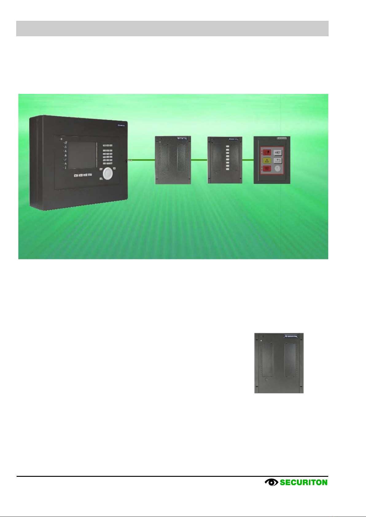
Fig.3 Topology of a SecuriFire 500 fire alarm control panel ....................................................................................................................5
Fig.4 SecuriFire FCP with built-in B7-MIC11 indication and control map ................................................................................................7
Fig.5 Schematic of an EPI-BUS..............................................................................................................................................................8
Fig.6 B5-EPI-PIM....................................................................................................................................................................................8
Fig.7 B5-EPI-PCM ..................................................................................................................................................................................9
Fig.8 B5-EPI-FPC...................................................................................................................................................................................9
Fig.9 B5-EPI-ASP...................................................................................................................................................................................9
Fig.10 B5-EPI-FAT..................................................................................................................................................................................9
Fig.11 B5-EPI-FPD .................................................................................................................................................................................9
Fig.12 B5-EPI-FPCZ.............................................................................................................................................................................10
Fig.13 B5-EPI-FPS-S............................................................................................................................................................................10
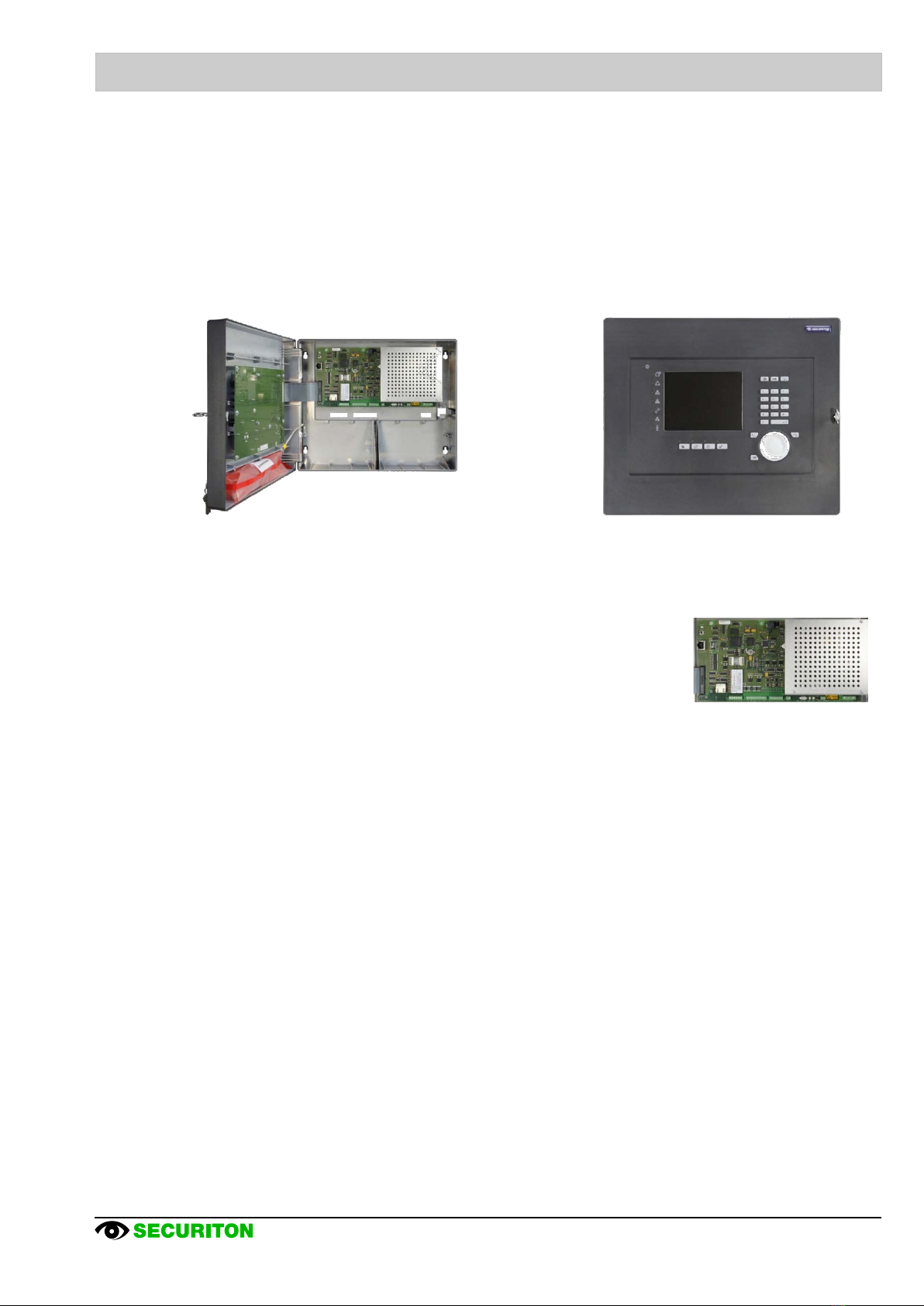
Fig.14 Basic circuit board with PSU and integrated MIC ......................................................................................................................11
Fig.15 Housing with operating panel....................................................................................................................................................11
Fig.16 Schematic of SecuriLine eXtended ring circuit..........................................................................................................................12
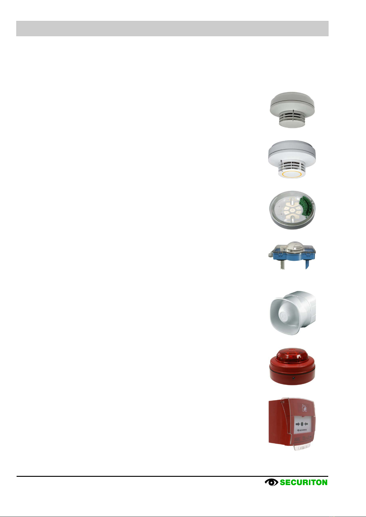
Fig.17 MCD 573X ................................................................................................................................................................................14
Fig.18 CCD 573X.................................................................................................................................................................................14
Fig.19 USB 501....................................................................................................................................................................................14
Fig.20 LKM 531....................................................................................................................................................................................14
Fig.21 BX-SOL.....................................................................................................................................................................................14
Fig.22 BX-FOL.....................................................................................................................................................................................14
Fig.23 MCP 545 X N............................................................................................................................................................................14
Fig.24 MCP 535...................................................................................................................................................................................15
Fig.25 BX-OI3......................................................................................................................................................................................15
Fig.26 BX-O2I4....................................................................................................................................................................................15
Fig.27 BX-AIM......................................................................................................................................................................................15
Fig.28 BX-IOM.....................................................................................................................................................................................15
Fig.29 BX-REL4...................................................................................................................................................................................15
Fig.30 BX-IM4......................................................................................................................................................................................15
Fig.31 BX-O1.......................................................................................................................................................................................15
Fig.32 BX-I2.........................................................................................................................................................................................16
Fig.33 BX-ESL.....................................................................................................................................................................................16

Securiton AG, Alarm and Security Systems
www.securiton.com, [email protected]
Securiton d.o.o., Serbia
www.securiton.rs, [email protected]
Securiton Kft., Hungary
www.securiton.hu, [email protected]
Securiton (M) Sdn Bhd. Malaysia
www.securiton.com, [email protected]
Securiton RUS, Russia
www.securiton.ru, [email protected]
A company of the Swiss Securitas Group
Other manuals for SecuriFire 500
1
This manual suits for next models
1
Table of contents
Popular Fire Alarm manuals by other brands

FIREWOLF
FIREWOLF FW-C01224 owner's manual

System Sensor
System Sensor PS12/24ADA Series Installation and maintenance instructions

Bosch
Bosch FPC-500 Operation manual

Kentec Electronics
Kentec Electronics Taktis quick start guide

Notifier
Notifier AVL-1 Operation and installation manual

Bosch
Bosch FMM-7045 installation instructions