SECURITY SENSOR BARRIER-24.M500 User manual

SECURITY SENSOR
BARRIER-24.M500
BARRIER-24.M300
BARRIER-24.M200
BARRIER-24.M100
BARRIER-24.M50
User Manual
EU-type examination CERTIFICATE
(Radio Equipment Directive 2014/EU, Annex III)
No. 0120-CC-V0008-20
2020

BARRIER-24.M500, BARRIER-24.M300, BARRIER-24.M200, BARRIER-24.M100, BARRIER-24.M50 www.SECURITY-SNESORcom
2 14.01.2021
Contents
Introduction ............................................................................................................................. 3
1 Description and Operation of the Sensor................................................................ 4
1.1 Purpose of the Sensor.............................................................................................. 4
1.2 Technical Specifications ......................................................................................... 5
1.3 Contents of the Device............................................................................................ 9
1.4 Structure and Operation .......................................................................................... 11
1.5 Measuring Devices, Instruments and Accessories.................................................. 16
1.6 Making..................................................................................................................... 17
1.7 Package.................................................................................................................... 17
2 Intended Use............................................................................................................ 17
2.1 Operation for Use.................................................................................................... 17
2.2 Preparation for Use.................................................................................................. 18
2.3 Installation and Configuration of the Sensors......................................................... 18
3 Technical Service.................................................................................................... 38
3.1 General Instructions ................................................................................................ 38
3.2 Safety Measures ...................................................................................................... 38
3.3 Technical Service Procedure................................................................................... 38
4 Troubleshooting Guide............................................................................................ 40
5 Storage..................................................................................................................... 41
6 Transportation ......................................................................................................... 41
7 Utilization................................................................................................................ 41
The list of registration of changes........................................................................................... 42

BARRIER-24.M500, BARRIER-24.M300, BARRIER-24.M200, BARRIER-24.M100, BARRIER-24.M50 www.SECURITY-SENSOR.com
3 14.01.2021
The present User Manual covers Protection Linear Microwave Bistatic sensors BARRIER-
24.M (general purpose) (referred to as the sensors for all the modifications) produced in
five modifications: BARRIER-24.M50, BARRIER-24.M100, BARRIER-24.M200,
BARRIER-24.M300, BARRIER-24.M500 differing in dimensions and maximum range of
operation.
The User Manual contains information necessary for learning the sensors and their
operation principle, mounting, powering the sensors and their correct exploitation.
The sensors contain the transmitter unit (referred to as Tx unit) and receiver unit (referred
to as Rx unit). The principle of operation is based on generation in the space between the
Tx unit and Rx unit of the electromagnetic field forming a volumetric detection zone in a
shape of a stretched ellipsoid of rotation and on registration of the alteration of this field in
the receiver in case of crossing the detection zone by an intruder.
The sensor triggers by breaking the contacts of the executive relay.
The sensors are to be used by the staff having learnt the present User Manual and having
practical skills in exploitation of technical security devices.
Start-up works and technical maintenance of the sensors in deployment site are to be made
by the staff having learnt the present User Manual.

BARRIER-24.M500, BARRIER-24.M300, BARRIER-24.M200, BARRIER-24.M100, BARRIER-24.M50 www.SECURITY-SNESORcom
4 14.01.2021
1 Description and Operation of the Sensor
1.1 Purpose of the Sensor
1.1.1 The Protection Linear Microwave Bistatic sensors BARRIER-24.M (general purpose)
are intended for the protection of flat open sites, for generation and transmission of
the alarm signal to the control panel in case of intruder crossing the protected site.
1.1.2 The sensors generate the alarm signal in the following cases:
when the detection zone is crossed by an intruder (a man from 50 kg and from
165 cm high) with the speed from 0,1 to 10 m/s «at his full height» or «bent»
with the probability not less than 0,98;
when the remote control signal is applied to the Tx unit;
when there is no signal from the Tx unit;
when an external electromagnetic field affects the Rx unit with the purpose to
mask it. It is allowed not to have the alarm signal when an external
electromagnetic field affects the Rx unit, in this case the sensor keeps its
working capacity;
when any of the units taking part in forming the detection zone is masked by a
screen;
when an unauthorized access to the control units takes place whether power on
or off;
when the power supply voltage drops below 9 V;
when Tx unit or Rx unit fails.
1.1.3 The sensors do not generate the alarm signal in the following cases:
–when a secondary standard target with linear dimensions up to 0,2 m is moving
within the detection zone at the distance of not less than 5 m from the units;
–when transport or a group of people is moving outside the detection zone at the
distance more than 1,5 m from the limit of the detection zone to the roadside
where such moving is possible;
when raining and snowing up to 40 mm/h;
when thick fog takes place;
when solar radiation takes place;
when winding up to 30 m/s;
when VHF emission in the band of 150-175 MHz up to 40 W takes place at the
distance more than 6 m.
1.1.4 The sensors exploitation conditions
–operating temperature range from minus 500C to plus 800C;
–relative air humidity up to 100% at the temperature of 250C with condensation of
moisture.

BARRIER-24.M500, BARRIER-24.M300, BARRIER-24.M200, BARRIER-24.M100, BARRIER-24.M50 www.SECURITY-SENSOR.com
5 14.01.2021
1.2 Technical Specifications
1.2.1 The configuration of the detection zone formed by the sensors installed on poles,
maximum operation range of the sensors, minimum operation range of the sensors,
width of the sensors detection zone, height of the sensors detection zone are given in
Figure 1.1 and Tables 1.1, 1.2.
Figure 1.1 –The configuration of the detection zone formed by the sensors installed
on poles
Notes
* For the sensors BARRIER-24.M50, BARRIER-24.M100, BARRIER-24.M200: at
the distance of 3-5 m from the poles, where the sensors Tx and Rx units are installed,
the probability of detecting the intruder moving «bent» is less than 0,98, because a
man can pass lower the detection zone.
** For the sensors BARRIER-24.M300, BARRIER-24.M500: the probability of
intruder detection by the sensors is equal on all the range of the detection zone and is
0,98, however the height of the detection zone close to the sensors Tx and Rx units is
reduced.
Table 1.1 –Maximum and minimum operation range of the sensors, width of the
detection zone
Names of sensors
Maximum
operation range
(L), m
Minimum
operation range
(L), m
Width of the
detection zone (b),
m, up to
BARRIER-24.M50
50
5
1,0
BARRIER-24.M100
100
10
1,5
BARRIER-24.M200
200
10
2,1
BARRIER-24.M300
300
10
2,7
BARRIER-24.M500
500
10
3,5

BARRIER-24.M500, BARRIER-24.M300, BARRIER-24.M200, BARRIER-24.M100, BARRIER-24.M50 www.SECURITY-SNESORcom
6 14.01.2021
Table 1.2 –Height of the sensors detection zone
Names of sensors
Height of the detection zone (h), m, not less than
BARRIER-24.M50
1,3*
BARRIER-24.M100
1,5*
BARRIER-24.M200
1,6*
BARRIER-24.M300
1,8*
BARRIER-24.M500
1,8*
____________________
* In the middle of the sector at the maximum range
1.2.2 The parameters of the sensors BARRIER-24.M (general purpose) correspond to the
values given in P. 1.2.1 while meeting the requirements on installation according to
Figure 1.2 and Table 1.3.
Figure 1.2 –Configuration of the protected site
Table 1.3 –Requirements to the parameters of the protected site
Length of the sector, m
10
25
50
100
200
300
500
Width of Zone А, m, not less
1,1
1,6
2,0
2,5
3,0
3,7
4,5
Width of Zone В, m, not less
0,5
0,7
1,0
1,5
2,1
2,7
3,5
Notes
1 Zone A should be free of:
–shrubs, trees, gates moving under the wind, etc.;
–moving people, animals.
2 No transport moving closer than 1 m from Zone A is allowed.
3 Provide in Zone B:
–grass up to 0,3 m high;
–snow up to 0,5 m high;
–irregularities of the ground up to ±0,3 m high;
–no foreign immobile objects and buildings
(separate poles not closer than 0,5 m from the axis of the sector are
allowed).

BARRIER-24.M500, BARRIER-24.M300, BARRIER-24.M200, BARRIER-24.M100, BARRIER-24.M50 www.SECURITY-SENSOR.com
7 14.01.2021
1.2.3 The shape of the detection zone generated by the sensors BARRIER-24.M50,
BARRIER-24.M100, BARRIER-24.M200 installed on the fence, maximum
operational range of the sensors, maximum width of the sensors detection zone,
maximum height of the sensors detection zone are given in Figure 1.3 and Table 1.4.
Figure 1.3 –The shape of the detection zone generated by the sensors BARRIER-24.M50,
BARRIER-24.M100, BARRIER-24.M200 installed on the fence
Table 1.4 –Maximum operational range, maximum width of the detection zone,
maximum height of the detection zone of the sensors BARRIER-24.M50, BARRIER-
24.M100, BARRIER-24.M200 installed on the fence
Name of sensors
Maximum length
of the sector (L),
m
Maximum width of
the DZ (B), m
Maximum height of
the DZ (Н), m
BARRIER-24.M50
40
1,0
1,0
BARRIER-24.M100
100
1,5
1,5
BARRIER-24.M200
100
1,5
1,5
Note –Maximum width (В) and maximum height (Н) of the detection zone
correspond to the given values in case the sensor is correctly configures according to
P.2.3.8.
L
B
H
Perimeter inside territory
Rx1
Tx1 Tx2
2,5...3,0 m

BARRIER-24.M500, BARRIER-24.M300, BARRIER-24.M200, BARRIER-24.M100, BARRIER-24.M50 www.SECURITY-SNESORcom
8 14.01.2021
1.2.4 The sensors operation frequency is 24,15 ± 0,10 GHz.
1.2.5 The sensors work by eight frequency channels (8 frequency letters).
1.2.6 The Tx and Rx units are synchronized by the radio beam.
1.2.7 The margin of the received radio signal is not less than 15 dB at the maximum
operation range of the sensors.
1.2.8 The time of the sensors technical readiness after power supply is ON is up to 60 s.
1.2.9 The duration of alarm is not less than 3 s.
1.2.10 The sensors recovery time to normal state after alarm is up to 10 s.
1.2.11 The sensors are powered from a direct current source with voltage from 9 t 30 V.
1.2.12 The sensors current consumption does not exceed 45 mA in all the band of supply
voltage.
1.2.13 The parameters of the executive relay: maximum commutated current up to 0,1 A,
maximum voltage up to 50 V, resistance in the closed state up to 110 Ohm (together
with the elements of lightning guard).
1.2.14 Load parameters of TAMPER button: current up to 0,2 A, voltage up to 80 V.
1.2.15 The sensors operation can be controlled remotely (see P. 3.3.2.1).
1.2.16 The sensors have LED indication of the state.
1.2.17 The input circuits of Tx unit and Rx unit are protected from short electric pick-up
(including storm) with amplitude up to 900 V.
1.2.18 The sensors are immune to electromagnetic interference according to GOST R
50009-2000, severity level 2.
1.2.19 The sensors contain two units –transmitter unit (Tx) and receiver unit (Rx),
protection level IP55 each.
1.2.20 The sensors can be configured and controlled in-field using the laptop working on
Windows platform.
1.2.21 The sensors can be configured and controlled in-field using the tablet working on
Android platform.
1.2.22 The sensors can be configured and controlled remotely using the computer.
1.2.23 Alarm and operation information is transmitted via the interface RS-485.
1.2.24 The Tx unit and Rx unit design assures maximum values of angles of rotation:
–on a bracket –not less than 600in horizontal plane and not less than 800in
vertical plane;
–about a support –360.
1.2.25 Mean time to failure –not less than 60000 hours.
1.2.26 Full mean lifetime –not less than 8 years.
1.2.27 Weight of the sensors including fixing elements, up to:
–2,9 kg for the sensors BARRIER-24.M300, BARRIER-24.M500;
–1,4 kg for the sensors BARRIER-24.M200, BARRIER-24.M100, BARRIER-
24.M50.

BARRIER-24.M500, BARRIER-24.M300, BARRIER-24.M200, BARRIER-24.M100, BARRIER-24.M50 www.SECURITY-SENSOR.com
9 14.01.2021
1.3 Contents of the Device
1.3.1 There are several modifications of the sensors depending on the maximum operation
range (see Table 1.5).
Table 1.5 –Modifications of the Protection Linear Microwave Bistatic sensors
BARRIER-24.M (general purpose)
Name
Security sensor BARRIER-24.M50
Security sensor BARRIER-24.M100
Security sensor BARRIER-24.M200
Security sensor BARRIER-24.M300
Security sensor BARRIER-24.M500
1.3.2 The completion of the sensors is given in Table 1.6
Table 1.6 –The completion of the Protection Linear Microwave Bistatic sensors
BARRIER-24.M (general purpose)
Name
Q-ty
Note
1
2
3
Protection Linear Microwave Bistatic sensor
BARRIER-24.M50
Transmitter unit
1
Receiver unit
1
Mounting kit
1
see Table 1.7
Kit of instruments and accessories
1
see Table 1.8
User Manual
1
Passport
1
Package
1

BARRIER-24.M500, BARRIER-24.M300, BARRIER-24.M200, BARRIER-24.M100, BARRIER-24.M50 www.SECURITY-SNESORcom
10 14.01.2021
Continuation of Table 1.6
1
2
3
Protection Linear Microwave Bistatic sensor
BARRIER-24.M100
Transmitter unit
1
Receiver unit
1
Mounting kit
1
see Table 1.7
Kit of instruments and
accessories
1
see Table 1.8
User Manual
1
Passport
1
Package
1
Protection Linear Microwave Bistatic sensor
BARRIER-24.M200
Transmitter unit
1
Receiver unit
1
Mounting kit
1
see Table 1.7
Kit of instruments and
accessories
1
see Table 1.8
User Manual
1
Passport
1
Package
1
Protection Linear Microwave Bistatic sensor
BARRIER-24.M300
Transmitter unit
Receiver unit
Mounting kit
see Table 1.7
Kit of instruments and
accessories
see Table 1.8
User Manual
Passport
Package
Protection Linear Microwave Bistatic sensor
BARRIER-24.M500
Transmitter unit
1
Receiver unit
1
Mounting kit
1
see Table 1.7
Kit of instruments and
accessories
1
see Table 1.8
User Manual
1
Passport
1
Package
1

BARRIER-24.M500, BARRIER-24.M300, BARRIER-24.M200, BARRIER-24.M100, BARRIER-24.M50 www.SECURITY-SENSOR.com
11 14.01.2021
1.3.3 The contents of the mounting kit is given in Table 1.7.
Table 1.7 –The contents of the MK
Name
Q-ty
Note
1
2
3
1 Mounting kit containing of:
1.1 Input of the corrugated hose
2
1.2 Corrugated tube РА601013F0
2
L=0,75 m
1.3 Buckle 70-90
4
2 Mounting kit containing of:
2.1 Bracket
2
2.2 Washer
2
2.3 Bolt DIN 933-M8x20-A2-70
2
2.4 Washer DIN 9021-8-140 HV-A2
2
2.5 Washer DIN 127-B 8-A2-70
2
2.6 Input of the corrugated hose
2
2.7 Corrugated tube РА601013F0
2
L=0,75 m
2.8 Buckle 70-90
4
1.3.4 The contents of the kit of instruments and accessories is given in Table 1.8.
Table 1.8 –The contents of the KIA
Name
Q-ty
Note
1
2
3
1 Kit of instruments and accessories
containing of:
1.1 Cable USB A-B
1
2 Kit of instruments and accessories
containing of:
2.1 Cable USB A-B
1
2.2 Spanner
1
S=4 mm
The purpose and the way of installation of additional products are given in the
present User Manual and exploitation documentation.
1.4 Structure and Operation
1.4.1 The sensors contain two units –transmitter unit (Tx unit) and receiver unit (Rx unit).
1.4.2 Structure of the sensors BARRIER-24.M50, BARRIER-24.M100, BARRIER-
24.M200.

BARRIER-24.M500, BARRIER-24.M300, BARRIER-24.M200, BARRIER-24.M100, BARRIER-24.M50 www.SECURITY-SNESORcom
12 14.01.2021
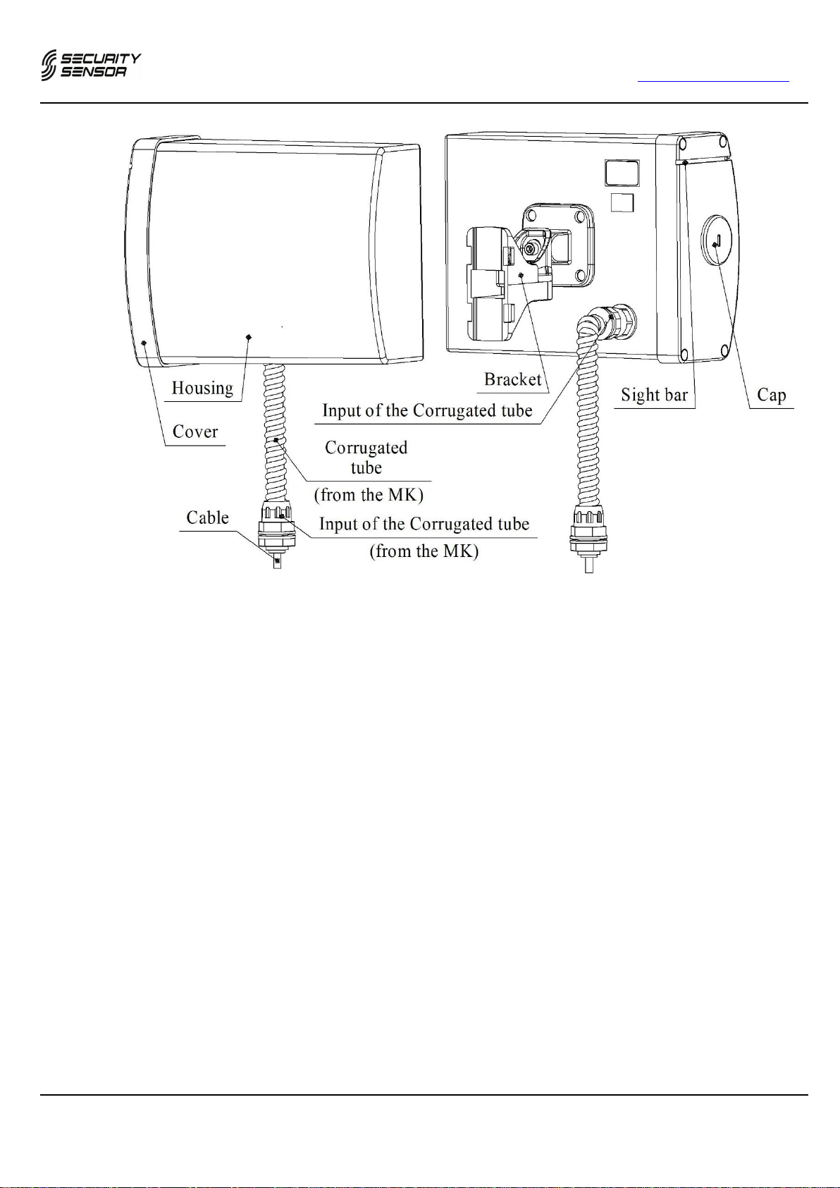
1.4.2.1 The Tx unit (overall dimensions 195,5х154,5х100 mm) (see Figure 1.4) contains a
plastic housing with a microwave module and a modulator with configuration
elements. The housing contains a parabolic insertion. The housing is closed with a
cover. On the bottom face of the housing there are two holes preventing the
condensate inside the Tx unit. On the cover there is a sight bar to make it easy to
adjust the sensor. The configuration elements are covered with a cap. The cap is
protected against unauthorized opening with a button. On the back face of the
housing there is a bracket for pole mounting of the unit. Use the 5-core cable brought
out from the unit through the input of the corrugated hose to connect the Tx unit to
the junction box or power supply unit.
1.4.2.2 The Rx unit (overall dimensions 195,5х154,5х100 mm) (see Figure 1.4) contains a
plastic housing with a microwave module and processing board with configuration
elements. The housing contains a parabolic insertion. The housing is closed with a
cover. On the bottom face of the housing there are two holes preventing the
condensate inside the Rx unit. On the cover there is a sight bar to make it easy to
adjust the sensor. The configuration elements are covered with a cap. The cap is
protected against unauthorized opening with a button. On the back face of the
housing there is a bracket for pole mounting of the unit. Use the 8-core cable brought
out from the unit through the input of the corrugated hose to connect the Tx unit to
the junction box or power supply unit.
BARRIER-24.M500, BARRIER-24.M300, BARRIER-24.M200, BARRIER-24.M100, BARRIER-24.M50 www.SECURITY-SENSOR.com
13 14.01.2021
Figure 1.4 –The design of the Tx unit (Rx unit) of the sensors
BARRIER-24.M50, BARRIER-24.M100, BARRIER-24.M200
Note –The appearance of the input of the corrugated hose and input of the
corrugated tube may differ depending on the shipment conditions
1.4.3 Structure of the sensors BARRIER-24.M300, BARRIER-24.M500
1.4.3.1 The Tx unit (overall dimensions 395х182х100 mm) (see Figure 1.5) contains two
connected with each other plastic housings, with microwave modules and parabolic
insertions inside. The upper housing contains the modulator with configuration
elements. The housings are covered with covers. The lower cover contains three
holes, preventing the condensate inside the Tx unit. On the upper cover there is a
sight bar to make it easy to adjust the sensor. The configuration elements are covered
with a cap. The cap is protected against unauthorized opening with a button. The unit
contains a bracket for pole mounting. Use the 5-core cable brought out from the unit
through the input of the corrugated hose to connect the Tx unit to the junction box or
power supply unit.
1.4.3.2 The Rx unit (overall dimensions 395х182х100 mm) (see Figure 1.5) contains two
connected with each other plastic housings, with microwave modules and parabolic
insertions inside. The upper housing contains the processing board with configuration
elements. The housings are covered with covers. The lower cover contains three
holes, preventing the condensate inside the Rx unit. On the upper cover there is a

BARRIER-24.M500, BARRIER-24.M300, BARRIER-24.M200, BARRIER-24.M100, BARRIER-24.M50 www.SECURITY-SNESORcom
14 14.01.2021
sight bar to make it easy to adjust the sensor. The configuration elements are covered
with a cap. The cap is protected against unauthorized opening with a button. The unit
contains a bracket for pole mounting. Use the 8-core cable brought out from the unit
through the input of the corrugated hose to connect the Rx unit to the junction box or
power supply unit.
Figure 1.5 –The design of the Tx unit (Rx unit) of the sensors BARRIER-24.M300,
BARRIER-24.M500
Note –The appearance of the input of the corrugated hose and input of the
corrugated tube may differ depending on the shipment conditions.

BARRIER-24.M500, BARRIER-24.M300, BARRIER-24.M200, BARRIER-24.M100, BARRIER-24.M50 www.SECURITY-SENSOR.com
15 14.01.2021
1.4.4 Configuration elements of the sensors BARRIER-24.M (general purpose)
1.4.4.1 The location of the configuration elements under the cap of the Tx unit (Rx unit) are
given in Figures 1.6, 1,7.
1 –socket «TEST»;
2 –indicator of the sensors state.
Figure 1.6 –Configuration elements of the Rx unit of the sensors BARRIER-24.М
(general purpose)
1 –socket «TEST».
Figure 1.7 –Configuration elements of the Tx unit of the sensors BARRIER-24.M
(general purpose)
1.4.5 The principle of operation of the sensors
1.4.5.1 The principle of operation of the sensors is based on making in the space between the
Tx unit and Rx unit the electromagnetic field generating a volumetric detection zone
in a shape of a stretched ellipsoid of rotation and on registering the alteration of this
field in the Rx unit in case of crossing the detection zone by an intruder.
1.4.5.2 The intrusion of a man into the detection zone generates the alteration of the signal
amplitude on the input of the Rx unit. The signal coming to the input goes through
the amplifier and on its output the signal is compared with the threshold values
according to the target algorithm, with that the useful signal is separated from the
noise. In case the analysis results show that the signal alteration on the input of the
Rx unit is caused by the intruder’s crossing, the Rx unit generates the alarm signal.

BARRIER-24.M500, BARRIER-24.M300, BARRIER-24.M200, BARRIER-24.M100, BARRIER-24.M50 www.SECURITY-SNESORcom
16 14.01.2021
1.4.5.3 The reception and indication of alarm signals is made by security systems (panels)
controlling the relay contacts. In case of alarm the normally closed relay contacts are
broken.
1.4.5.4 The alarm information is duplicated via the interface RS-485.
1.4.6 Operation of the sensors
1.4.6.1 After the sensor is powered, it makes self-performance test during up to 60 s.
In case self-performance test is successful the sensors goes to stand-by mode.
When triggering the sensor generates the alarm signal not less than 3 s long.
After that the sensor goes to normal state in up to 10 s.
1.5 Measuring Devices, Instruments and Accessories
1.5.1 In order to provide adjustment and configuration of the sensors during exploitation
use the following devices:
–laptop on Windows with the cable USB A-B (not included into the delivery kit);
–tablet on Android with the cables USB A-B (not included into the delivery kit)
and OTG (not included into the delivery kit);
–remote PC connected to the sensor via the interface RS-485 using the interface
converter.

BARRIER-24.M500, BARRIER-24.M300, BARRIER-24.M200, BARRIER-24.M100, BARRIER-24.M50 www.SECURITY-SENSOR.com
17 14.01.2021
1.6 Marking
1.6.1 The sensors marking contains:
–trademark of the factory manufacturer;
–name of the sensor unit;
–factory serial number;
–year and quarter of manufacture.
1.6.2 The transport and consumer package marking contains:
–name of the sensor;
–name of the factory manufacturer, its trademark;
–postal address, telephone (fax) number, e-mail and official Website in Internet of
the factory manufacturer;
–conformity marks;
–packing date;
–handling symbols and transportation conditions symbols.
1.7 Package
1.7.1 The sensors are packed into the transport and consumer package, assuring the safety
of the products packed during transportation and storage according to the
manufacturer documentation.
2 Intended Use
2.1 Operating Limitations
2.1.1 The sensors are to be used in conditions according to p. 1.1.4. of the present User
Manual only.
2.1.2 The shape and parameters of the sector where the sensors will be installed and its
requirements are to meet the requirements given in P. 1.2.2.
2.1.3 Maximum inclination of the sector is 40º.
2.1.4 The alteration of the signal depends on the height and weight of the person, his speed
of crossing, place of crossing the sector and landscape shape.
2.1.5 The signal on the input of Rx unit can be changed under the influence of interference
factors, for example: precipitations, vegetation, small animals, electromagnetic noise,
moving of tree branches, doors fallen into the detection zone comparable in
amplitude with the intrusion of a man.
2.1.6 The following factors can influence the level of the input signal of Rx unit: location
of long buildings or objects (fence, walls, etc.) within or in the immediate proximity
of the detection zone, landscape irregularities, snow or vegetation on the site. In this
case the shape of the detection zone is deformed due to rereflection and interference.

BARRIER-24.M500, BARRIER-24.M300, BARRIER-24.M200, BARRIER-24.M100, BARRIER-24.M50 www.SECURITY-SNESORcom
18 14.01.2021
2.1.7 On sites with extra storm danger it is necessary to use external lightning guard units
(LGU). It is recommended to use lightning guard units in case the connection lines is
more than 300 m.
2.2 Preparation for Use
2.2.1 Safety Measures
2.2.1.1 Mounting, start-up works, service of the products can be made by persons
comprehensively studied the present User Manual.
2.2.1.2 Follow the safety standards of work with hardware under operating voltage up to
1000 V during technical service of the product.
2.2.1.3 IT IS PROHIBITED TO MOUNT AND START-UP THE PRODUCT DURING
STORM DUE TO RISK OF ELECTRIC SHOCK DURING STORM DISCHARGE
FROM PICK-UP IN COMMUNICATION LINE.
2.2.1.4 Power off the sensors to lay and cut the cables and to connect them to sensors units.
2.2.1.5 The sensors units are powered from direct current source with voltage 5 … 30 V or
from the alternative current mains with voltage 220 V. That is why it is necessary to
study the exploitation documentation on the power supply unit before starting works.
2.2.1.6 Installation, maintenance and repair of sensors can be made by persons got through
special instructions and passed exams on safety standards.
2.2.2 Unpacking and examining of the product
2.2.2.1 Examine carefully the package and make sure that it is not damaged before opening.
Check the presence of Quality Department stamp on the package before opening.
2.2.2.2 Open the package inside the building or under the roof. Avoid ingestion of
precipitations and aggressive environment on the sensors during opening.
2.2.2.3 Check the sensor completion.
2.2.2.4 Check the presence of Quality Department stamp in the sensor passport.
2.2.2.5 No mechanical damage like deep scratches, defects are allowed on the sensor surface.
2.3 Installation and Configuration of the Sensors
2.3.1 General Guide
2.3.1.1 Locate the sensors on the exploitation site according to the requirements of the
present User Manual and project recommendations on the security system.
2.3.1.2 Technologic sequence of mounting procedures is determined on the basis of
operational comfort.
2.3.1.3 The sensors installation should assure comfortable feed through of cables and free
access to them during mounting, exploitation, service.

BARRIER-24.M500, BARRIER-24.M300, BARRIER-24.M200, BARRIER-24.M100, BARRIER-24.M50 www.SECURITY-SENSOR.com
19 14.01.2021
2.3.1.4 Do electrical fitting of the sensors, connection to junction boxes and power supply
unit according to the security system project.
2.3.2 Installation procedure of the sensors BARRIER-24.M (general purpose).
2.3.2.1 Meet the requirements of P. 2.1.2.
2.3.2.2 Mark the perimeter for the placed of installation of poles.
2.3.2.2.1 Overlap the detection zones of the adjacent sectors (see Figure 2.1) for continuous
long protection boundary. Overlapping is necessary to avoid crossing the detection
zone under or above Tx unit (Rx unit) close to the pole.
It is not allowed to co-install Tx unit and Rx unit of the adjacent sectors. Correct
installation of the units of the adjacent sectors is –Tx unit with Tx unit, Rx unit with
Rx unit.
Install sensors with different frequency letters on adjacent sectors. Repeat
sequentially the frequency letter from 1 to 8 when installing the sensors on the sectors
following in succession assuring maximum distance between the sensors with the
same frequency letters.
Figure 2.1 –Example of perimeter marking for sensors installation

BARRIER-24.M500, BARRIER-24.M300, BARRIER-24.M200, BARRIER-24.M100, BARRIER-24.M50 www.SECURITY-SNESORcom
20 14.01.2021
2.3.2.2.2 For continuous long protection boundary with the sensors BARRIER-24.M300,
BARRIER-24.M500 it is allowed to install two Tx units (Rx units) on one pole
without overlapping the detection zones of adjacent sectors (see Figure 2.2).
Figure 2.2 –Installation of Rx units (Tx units) of the sensors BARRIER-24.M300,
BARRIER-24.M500 on one pole without overlapping the adjacent detection zones
Note –With this method of installation of the sensor units (standard height of
installation of the units is 0,85m from the earth surface) the detection
probability of an intruder crossing the detection zone «at his full height» or
«bent» (height of a bent person is 0,9-1,0 m), is equal on all the range of
the detection zone and is 0,98, however the height of the detection zone
close to the sensor units reduces.
If the reducing of the height of the detection zone close to the sensor units
is critical, follow the procedure in P. 2.3.2.2.1.
2.3.2.3 Install the poles. It is recommended to use metal tubes 70 … 90 mm in diameter for
poles. Assure the height of the pole not less than 1100 mm above the ground. In
This manual suits for next models
4
Table of contents


