Securitytec PTZ10EXPRO User manual

High Speed
Micro Dome Camera
Instruction Manual
(English Version)
Indoor Version Outdoor Version
Please read this manual thoroughly before use or installation and keep it handy for future reference.

2
WARNINGS AND CAUTIONS
WARNING
TO REDUCE THE RISK OF FIRE OR ELECTRIC SHOCK, DO NOT EXPOSE THIS PRODUCT TO RAIN OR
MOISTURE. DO NOT INSERT ANY METALLIC OBJECTS THROUGH VENTILATION GRILLS OR OPENINGS ON
THE EQUIPMENT.
CAUTION
EXPLANATION OF GRAPHICAL SYMBOLS
The lighting flash with arrowhead symbol, within an equilateral triangle, is intended to alert the user the
presence of non-insulated “dangerous voltage” within the product’s enclosure that maybe of sufficient
magnitude to constitute a risk of electric shock to different persons.
The exclamation point within an equilateral triangle, is intended to alert the user the presence of
important operating and maintenance (servicing) instructions in the literature accompanying this product
PRECAUTIONS:
1. Persons without technical qualifications should not attempt to operate this dome device before reading this manual
thoroughly.
2. Remove any power to the dome before attempting any operations or adjustments inside the dome cover to avoid
potential damage to the mechanism.
3. Inside the dome cover there are precision optical and electrical devices. Heavy pressure, shock and other sudden
adjustments or operations should be avoided. Otherwise, you may cause irreparable damage to the product.
4. Please DO NOT remove or disassemble any internal parts of the video camera to avoid normal operation and possibly
void the warranty. There are no serviceable parts inside the camera.
5. All electrical connections to the dome should be made in strict accordance with the attached labels and wiring
instructions in this manual. Failure to do so may damage the dome beyond repair and void the warranty.
6. For outdoor installation especially in high places or poles, it is highly recommended that the proper lightning arrestors
and surge suppressors are installed before the dome is entered into service.
7. Please do not use the product under circumstances where the limits exceed the maximum specified temperature,
humidity or power supply specifications.
3
FCC COMPLIANCE STATEMENT
CE COMPLIANCE STATEMENT
FCC INFORMATION: THIS EQUIPMENT HAS BEEN TESTED AND FOUND TO COMPLY
WITH THE LIMITS OF A CLASS A DIGITAL DEVICE, PURSUANT TO PART 15 OF THE FCC
RULES. THESE LIMITS ARE DESIGNED TO PROVIDE REASONABLE PROTECTION
AGAINST HARMFUL INTERFERENCE WHEN THE EQUIPMENT IS OPERATED IN A
COMMERCIAL ENVIRONMENT. THIS EQUIPMENT GENERATES, USES, AND CAN
RADIATE RADIO FREQUENCY ENERGY AND IF NOT INSTALLED AND USED IN
ACCORDA
NCE WITH THE INSTRUCTION MANUAL, MAY CAUSE HARMFUL
INTERFERENCE TO RADIO COMMUNICATIONS. OPERATION OF THIS EQUIPMENT IN A
RESIDENTIAL AREA IS LIKELY TO CAUSE HARMFUL INTERFERENCE IN WHICH CASE
THE USER WILL BE REQUIRED TO CORRECT THE INTERFERENCE AT HIS OWN
EXPENSE.
CAUTION
: CHANGES OR MODIFICATIONS NOT EXPRESSLY APPROVED BY THE
PARTY RESPONSIBLE FOR COMPLIANCE COULD VOID THE USER’S AUTHORITY TO
OPERATE THE EQUIPMENT.
THIS CLASS A DIGITALAPPARATUS COMPLIES WITH CANADIAN ICES-003.
CET APPAREUIL NUMERIQUE DE LA CLASSE A EST CONFORME A LA NORME NMB-003
DU CANADA
THIS IS A CLASS A PRODUCT, IN A DOMESTIC ENVIRONMENT THIS PRODUCT MAY
CAUSE RADIO INTERFERENCE IN WHICH CASE THE USER MAY BE REQUIRED TO
TAKE ADEQUATE MEASURES.

4
IMPORTANT SAFEGUARDS
1. Read these instructions before attempting installation or operation of dome device
2. Keep these instructions for future reference
3. Heed all warnings and adhere to electrical specifications
4. Follow all instructions
5. Clean only with non abrasive dry cotton cloth, lint free and approved acrylic cleaners
6. Should the lens of the camera become dirty, use special lens cleaning cloth and solution to
properly clean it.
7. Do not block any ventilation openings.
8. Install in accordance with manufacturer’s instructions
9. Use only attachments or accessories specified by the manufacturer
10. Verify that the surface you are planning to use for attaching the dome can adequately support
the weight of the device and mounting hardware
11. Protect this devices against lighting storms with proper power supplies
12. Refer all servicing to qualified service personnel. Servicing is required when the device has
been damaged in any way, when liquid traces are present, or the presence of loose objects is
evident or if the device does not function properly, or has received sever impact or has been
dropped accidentally.
13. Indoor dome is for indoor use only and not suitable for outdoor or high humidity locations. Do
not use this product under circumstances exceeding specified temperature and humidity ratings.
14. Avoid pointing the camera directly to the sun or other extremely bright objects for prolonged
period of time avoiding the risk of permanent damages to the imaging sensor.
15. The attached instructions are for use by qualified personnel only. To reduce the risks of electric
shock do not perform any servicing other than contained in the operating instructions unless
you are qualified to do so.
16. During usage, user should abide by all electrical safety standards and adhere to electrical
specifications for the operation of the dome. The control cable for RS485 communications as
well as the video signal cables should be isolated from high voltage equipment and or high
voltage cables.
17. Use supplied or Certified / Listed Class 2, 24 VAC power supply transformer only.

5
Table of Contents
1Chapter 1 – Introduction
1.1 Performance Characteristics .......................................................................................................................... 7
1.2 Model Numbers ...........................................................................................................................................8
1.3 Features and Functions .................................................................................................................................. 8
2Chapter 2 – Installation and configuration
2.1 Package contents............................................................................................................................................9
2.2 Camera shroud removal and installation........................................................................................................ 10
2.3 Communication settings................................................................................................................................. 11
2.4 Wall bracket installation................................................................................................................................. 13
2.5 Attaching the dome to the bracket ................................................................................................................. 14
2.6 Installation of the acrylic dome cover............................................................................................................ 15
2.7 Wiring Harness Specifications....................................................................................................................... 16
3Chapter 3 – Wiring and Setup
3.1 Basic Configuration....................................................................................................................................... 17
3.2 Connecting Multiple Domes..........................................................................................................................18
4Chapter 4 – Quick Start Operation Guide
4.1 Connecting power to the dome ...................................................................................................................... 19
4.2 Setting joystick protocol and baud rate. .......................................................................................................19
4.3 Start testing ....................................................................................................................................................19
4.4 Complete the test ...........................................................................................................................................19
4.5 Direct input Commands for dome operation.................................................................................................. 20
4.6 Camera OSD menu........................................................................................................................................22
5Chapter 5 – Program and Operation
5.1 Main menu.....................................................................................................................................................23
5.2 Tree Menu List............................................................................................................................................... 24
5.2.1 Language Options .................................................................................................................................. 25
5.2.2 Display options ...................................................................................................................................... 25
5.2.3 Control options....................................................................................................................................... 31
5.2.4 Diagnostic Options................................................................................................................................. 35
5.2.5 Camera Options...................................................................................................................................... 36, 41
5.2.6 Program Vector Scan.............................................................................................................................. 36
6Chapter 6 – Direct Command entry (Short-cuts) & Technical Specifications
6.1 Command reference table....................................................................................................................... 46
6.2 Technical Specifications......................................................................................................................... 47
7Chapter 7 – Trouble Shooting.............................................................................................................................. 48
8Chapter 8 – Appendix Glossary........................................................................................................................... 50

6
1. Introduction
The Speed domes and a series of compatible keyboard controllers make up the building blocks for any
size video surveillance system. Using multiple keyboard controllers and multiple high speed dome
camera units, one can monitor a variety of environments from small to very large. Extensive and
flexible architecture facilitates remote control functions for a variety of external switching devices
such as multiplexers and DVRs.
1.1 Performance Characteristics
•Built-in 10x (times) Optical power zoom camera with true day night capability
•1~255 individually addressed units. The dome address is defined using a dip switch with 8
positions (Binary addressing scheme)
•Integrated multi-protocol selected via Dip Switch settings for Pelco D and Pelco P.
Note: The dome can auto differentiate the protocol of the controller only on power up.
•Continuous Pan 360 degree rotation (slip ring).
•90 degree Tilt action plus 2 degree angle adjustment (the view angle can be 90 or 92 degrees).
•Pan speed in manual operation is variable from 0.1 up to 240 degrees per second
•Tilt speed in manual operation is variable from 0.1 to 100 degrees per second
•128 preset positions. (A preset position is defined as a user definable setting for precise
coordinates , pan, tilt and zoom on all 3 axis)
•The maximum speed when a preset position is called can reach 300 degrees per second with
positioning accuracy of ±0.1 degree.
•Compatible with a variety Camera Modules (Hitachi, Samsung)
•Input power supply: 24 VAC – 0.5Amp (indoor or outdoor model)
•User friendly on screen camera menu interface for ease of installation.
•Environmental protection conforming to IP66 standards (outdoor model)
•RS-485 (long distance) communications mode.
•Selectable transmission speed, (i.e. Baud rate). User definable via dip switch settings from
2400bps~19200bps

7
1.2 Model Numbers
Model No: 1 Dome Indoor High Speed Housing with OSD
Model No: 2 Dome Outdoor High Speed Housing with OSD
1.3 Features and Functions
•Multi-language on screen menu for operation and function settings.
•On screen Camera title with exact x/y coordinates. (The camera title is user definable as well as
the ability to display or not the camera coordinates)
•Six user definable vector scans (including scan speed, dwell time, preset and dwell time between
tours)
•Auto flip function with + 10 degree positioning
•Six sectors of user programmable privacy zones (sectional mask). User can mask part of the
camera sectors which differs between different models of installed cameras.
•Six sectors of user programmable sectional display. User can define and display the name and
position of the camera, which differs between different models of installed cameras.
•Resume automatic operation after initial self-test of the dome as well as resume automatic
operation when there is no transmission from a keyboard controller. (Dwell time can be set from
1 to 999 seconds)
•Freeze frame function.
•Resume operation function. (Dome unit will return to the previous operation after the execution
of an operation using the on screen menu)
•Intelligent manual scan function.(By executing this function in manual pan operation, you can
adjust the manual pan behavior of the dome)
•Intelligent power off real time memory.(Should power fail while the dome was in operation , the
dome will resume its preprogrammed function upon power restore)
•Zoom and dome speed correlation function. (When the camera is zoomed in close, the dome
speed is reduced to allow for precise operation control)

8
2.0 Installation & Configuration
2.1 Package Contents
The dome carton contains the following:
Description Qty
High Speed Dome mechanism 1
Camera Module 1
(Samsung 10x or Hitachi 10x)
Clear Acrylic dome cover 1
Camera shroud (black) 1
Plastic bag W/ Screws
(Secret Screw)
+ Mini Screwdriver
O-ring + Adapter for wall or ceiling bracket
6 conductor Control/Power/Video harness 1
24VAC transformer 1500 mA 1
Wall bracket 1
Suspend bracket 4” 1
Instruction manual 1
Figure 1. Illustrates the upper layer of the packing material (top half)
Figure 2. Illustrates the lower layer of the carton (bottom half).
Fig.1 Fig. 2
Manual and Quality certificate,
placed on top (not illustrated)
Cable Harness and connectors
24 VAC, 1.5 Amp
Transformer
Wall Bracket
Screws + Adapter
+ O ring
High Speed Dome & Camera
Ceiling Adapter
Base Suspend Adapter
Spacer 4”

9
2.2 Camera Shroud removal / installation.
Figure 10. Illustrates the camera shroud in position over the camera module
Figure 11. Illustrates the location of the tab for the camera shroud in close position (twist On/Off)
Fig. 10 Fig. 11
The dome is equipped with a quick release camera liner supported by 3 tabs attached to a ring affixed
on the PTZ mechanism. The liner needs to be removed in order to reach the dip switch settings of the
dome for proper addressing and selection of the communication protocol / baud rate.
Step 1: Restrict the movement of the dome
mechanism and rotate the camera liner
counterclockwise from “close” to “open”
position as illustrated.
Step 2: Remove the camera liner to
gain access to the dip switch
settings located on the
PC-Board underneath the
camera.
Note: Illustrations are for reference purposes only and may vary from actual package contents depending selected
installation options at time of order.

10
2.3 Communication Settings
2.3.1 Dip Switch Location.
Before installation and use, the unique address for each dome and the communication protocol including
transmission speed (baudrate) should be set to correspond with the chosen control system. In order to set the
corresponding dip-switches remove the camera liner as previously illustrated and locate the two Dip-Switch
rows (8 & 4) behind the camera module on the main PCB as illustrated.
2.3.2 Setting the address, protocol and baud rate for each dome device.
Note: The illustration shows the two Dip-Switches.
The switch on the left (8 position) is for the dome
address while the switch on the right is for the
protocol and baudrate settings.
The Table in the illustration provides the settings
for the two protocols supported, Pelco -D and
Pelco -P as well as the baudrate settings.
This illustration demonstrates the settings for
Dome Address 1, with Protocol Pelco -P at a baud
-rate of 4800 setting.
CAUTION: The protocol and baudrte of dome device should match the settings of the controller.
In order for the settings to take effect the dome must be power cycled after each change.

11
2.3.3Address setting of each dome. To prevent damage, each dome must have a unique address (ID).
Dome device range: 1~255.
2.3.4Addressing Examples 1-15
Address SW1 SW2 SW3 SW4 SW5 SW6 SW7 SW8
1
ON
OFF
OFF
OFF
OFF
OFF
OFF
OFF
2
OFF
ON
OFF
OFF
OFF
OFF
OFF
OFF
3 ON ON OFF OFF OFF OFF OFF OFF
4 OFF OFF ON OFF OFF OFF OFF OFF
5 ON OFF ON OFF OFF OFF OFF OFF
6 OFF ON ON OFF OFF OFF OFF OFF
7 ON ON ON OFF OFF OFF OFF OFF
8 OFF OFF OFF ON OFF OFF OFF OFF
9
ON
OFF
OFF
ON
OFF
OFF
OFF
OFF
10
OFF
ON
OFF
ON
OFF
OFF
OFF
OFF
11
ON
ON
OFF
ON
OFF
OFF
OFF
OFF
12
OFF
OFF
ON
ON
OFF
OFF
OFF
OFF
13 ON OFF ON ON OFF OFF OFF OFF
14 OFF ON ON ON OFF OFF OFF OFF
15 ON ON ON ON OFF OFF OFF OFF
Setting address for dome device
(this figure shows the address of
dome device No 1).
On/Off switch
Example: The sum of switch numbers in the ON position is the
address of the dome device. (Binary Method)
Calculation example
of dome device address:
1
2
4
8 16
32
64
128
(2+4+16=22)the dome address is: 22
On/off switch and
matching numbers
12
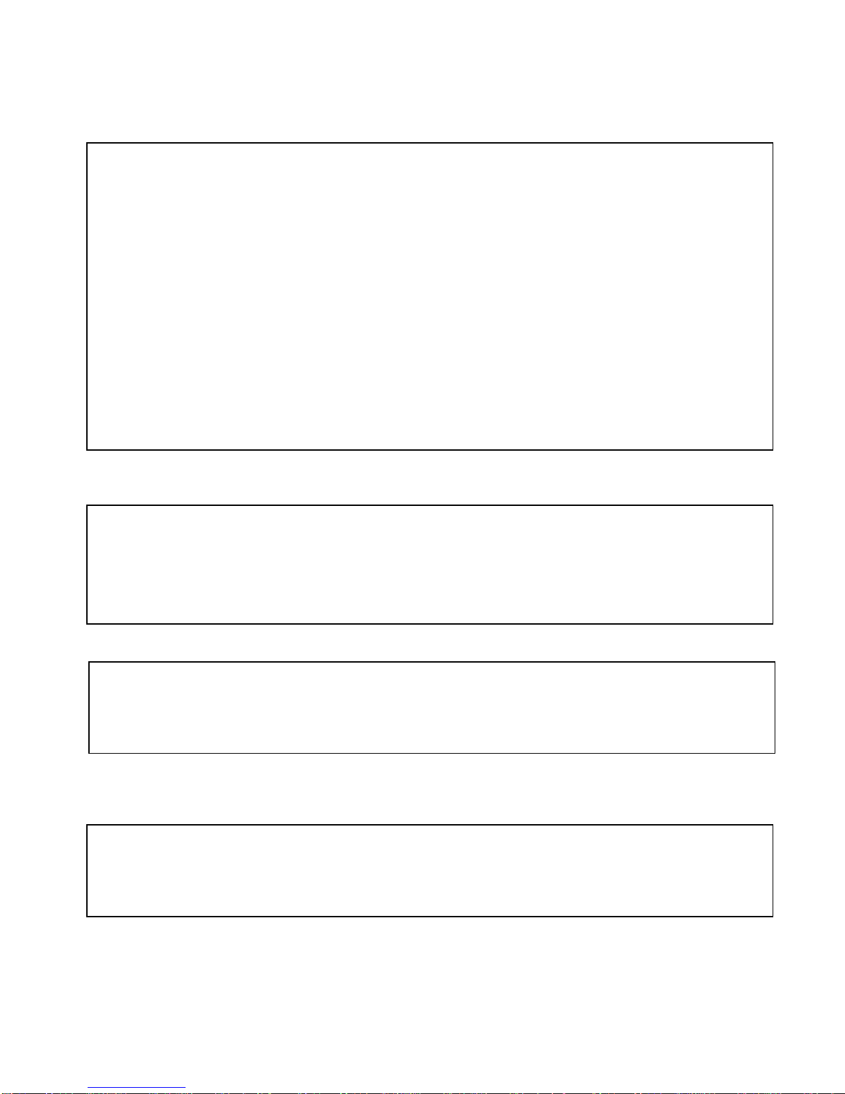
2.4 Wall bracket installation.
Step 1:Feed the supplied wiring harness through the channel inside the wall bracket as
illustrated in Fig. 13. Verify that the 6 pin connector is remaining outside the
opening of the bracket as illustrated in Fig. 14.
Fig. 13 Fig. 14
Step 2:Affix the wall bracket to the wall as illustrated in Figure 15 verifying that the
surface you are attaching to can support the weight of the dome using either expanding
anchors or butterfly fasteners.
Fig. 15 Fig. 16
Note: Different bracket options may be available. Illustrations are for reference purposes only and may vary from
actual package contents depending selected installation options at time of order.
13
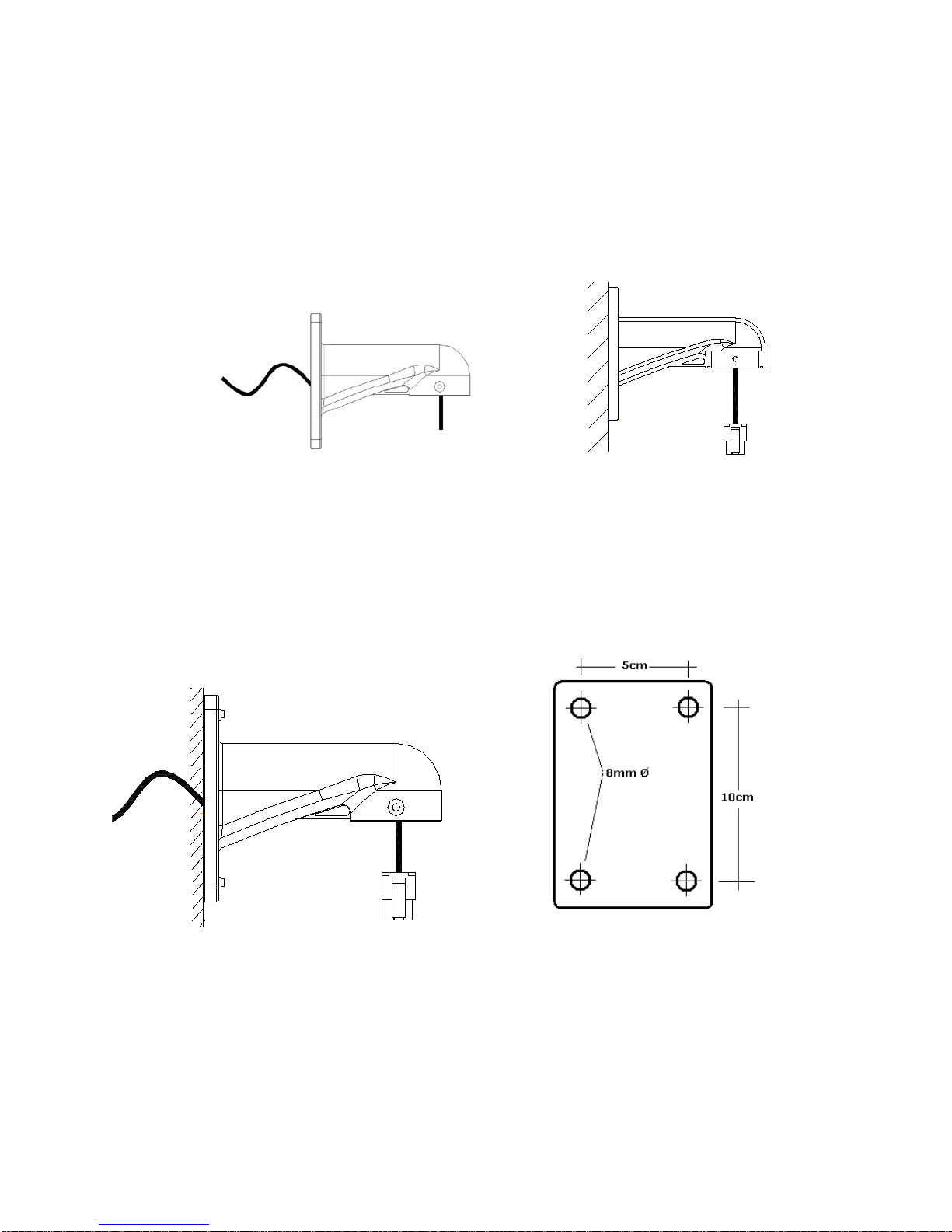
2.5 Attaching the dome to the bracket
Step 1: Locate the small plastic bag containing the O-ring,
adapter, screws, and small screwdriver as illustrated.
Step 2: Install the O-ring onto the wall bracket as illustrated.
Step 3: Install the adapter onto the top of the dome as
illustrated.
Step 4: Suspend the dome to the bracket using the stainless
hook as illustrated.
Step 5: Connect the end of the wiring harness protruding out
of the bracket to the mating connector on the dome
unit. Observe proper orientation of the connectors as
illustrated.
Step 6: Push the dome into the bracket and align the holes.
Using the supplied screws (with the two rubber
O-rings) secure the dome in place as illustrated.
When finished the dome should look like the illustration on
the right ready to be powered up.
Note: It is important that you set the dip switch settings
for the dome address and communication
parameters and protocol BEFORE you install the
dome in its physical location of operation.

14
2.6 Installation of the acrylic dome cover
The dome cover has two parts, a metal aluminum ring and a clear acrylic dome. The metal ring has
male fine threads that will allow it to mate with the aluminum cover of the dome mechanism.
Caution should be exercised when handling the clear dome preventing any abrasions or scratches to
the surface as this will affect the optical performance of the camera.
Step 1:Carefully align the two parts as illustrated in Figure 17.
Slowly rotate counterclockwise until a small click is
felt indicating the beginning of the threads.
Step 2:Slowly start rotating the bottom part (clear acrylic) in a
clockwise direction without forcing the threads as
illustrated in Figure 18. It takes approximately three (3)
complete rotations to have a complete seal.
Step 3:The dome arrives with a protective film. The illustrations
above are shown for clarity without the film in place.
When finished with the installation remove the plastic
protective film avoiding any contact if possible with the
lens. Should you need to clean it use only lens cleaning
solution and a soft non abrasive
cloth.
Fig. 17 Align the two parts
Fig. 19 Protection film of acrylic shield
Fig. 18 Rotate clockwise as indicated
15
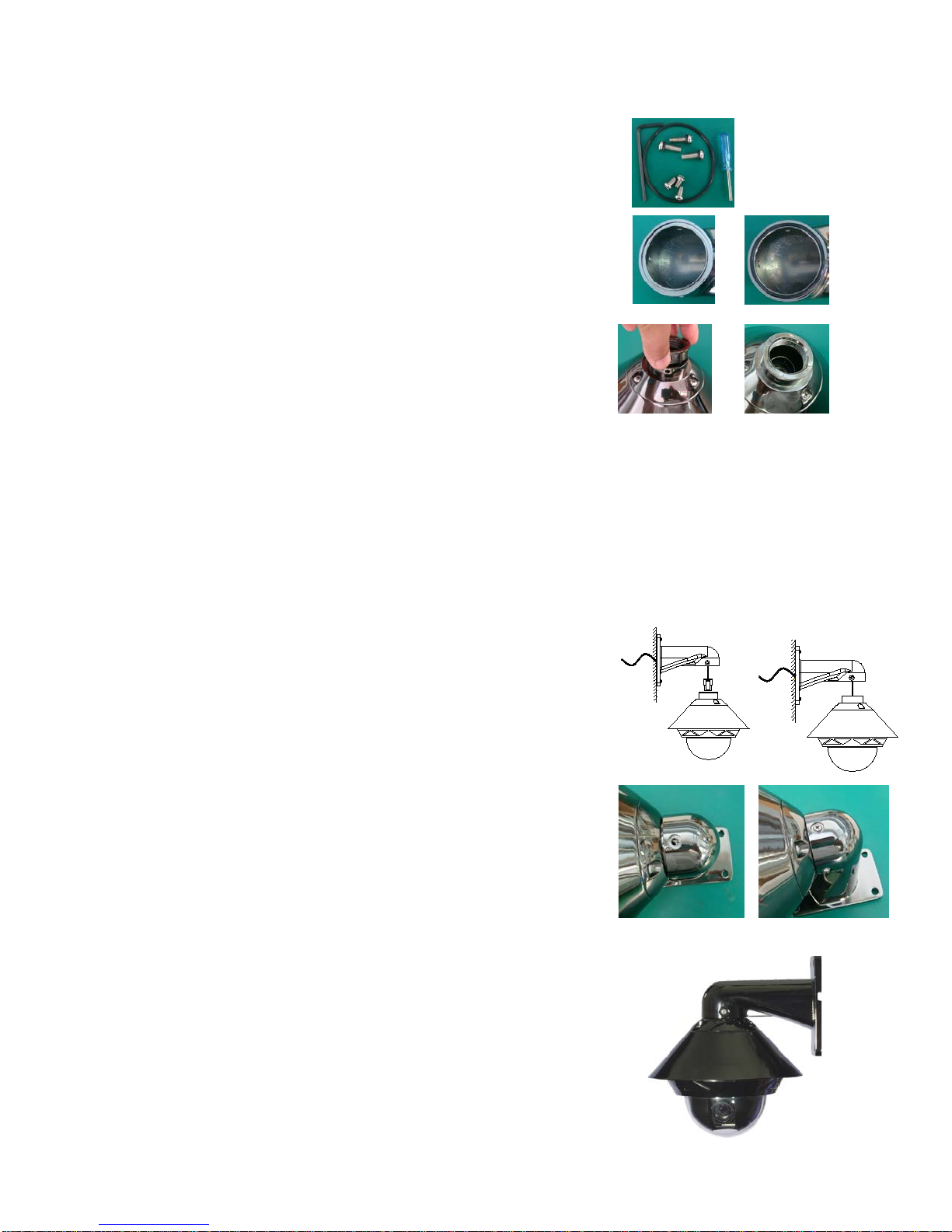
2.7 Wiring Specifications
The wiring Harness has a label affixed indicating the Power, Video and Communication
conductors. Do not remove this label as it may be a useful future reference.
Figure 20 is the illustration of the wiring diagram for the electrical connections to the dome unit.
Fig. 20
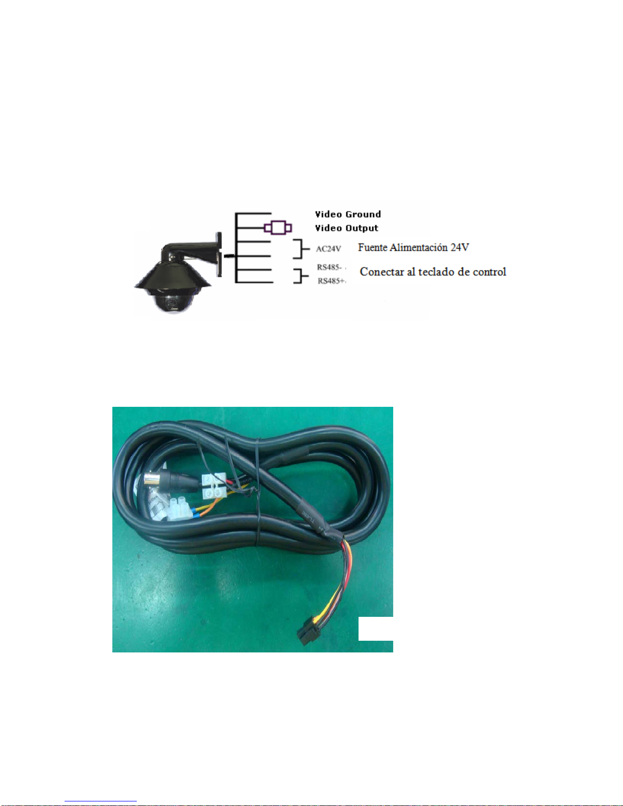
Figure 21 illustrates the wiring harness included with the dome.
Fig. 21
Video output, BNC Connector
Red: 24VAC power supply
Black: 24VAC power supply
Orange: RS485+
Yellow: RS485-
Modular Plug, Connect to the dome

16
Chapter 3: Wiring and Setup
3.1 Basic Configuration
The illustration below provides the basic electrical wiring configuration for connecting and testing a single dome to a
test monitor and a joystick / keyboard controller. When installing the product for the first times please read the
installation instructions carefully and become familiar with the electrical connections and setup options. Incorrect
wiring may result to permanent damage of the equipment.
12V(-)
12V(+)
RS485-(yellow)
Dome device
controller
Power of
keyboard
RS485+(orange)
AC24V(Black)
AC24V(Red) Power of
dome device
Video+
Video-
Image
displayer
AC24V(+)
AC24V(-)
RS485(-)
Caution: Connections to the dome should be performed with the power removed (Power OFF).
6 Pin Header
Connector

17
3.2 Connecting Multiple Domes
When connecting multiple domes together, the user has the option to connect video and control
terminals to a video matrix switcher or a DVR multiplexer creating an integrated system.
AC24V: Power supply Primary220V/110V/60HZ input to AC 24V output.
RS-485 Bus: Control signal output from joystick controller, connected in a bus configuration to
the RS485 communication terminals of the control cable for each dome.
Video: Signal output from the dome camera connected to a monitor, DVR, or video matrix.
Take into consideration impedance matching and or termination.
18
4. Quick Start Operation Guide
CAUTION: Do not turn the power ON until you have finished all connections and communication settings).
4.1 Connect the power to the dome.
As soon as the power is turned ON, the dome initiates a self test which includes a rotation of the dome on both axis and
the camera will display a brief menu followed by a live image on the monitor.
Note:During self-testing, it is normal to hear a clicking sound caused by the camera module for about 2~5 seconds of
vertical movement, as a result of the vertical self alignment.
4.2 Joystick controller setting.
Set the protocol, baud rate, and address of the keyboard controller to match the settings on the dome
(For instructions of how to set the keyboard communication settings please refer to keyboard controller manual).
Attention: If the protocol setting of the dome is set to auto detection, the protocol of keyboard controller can be set
arbitrarily. But its baud rate should be set identical with that of the dome device.
4.3 Start testing.
When all of the above settings are completed you can start testing the dome functionality.
1. Direction control test of dome device 2. Zooming control test of camera
(Please refer to the next section for demonstration of menu operation and control of dome device.)
4.4 Complete the test.(Summary).
If you have achieved control of the dome device as described in section 4.6 above, the system is
basically normal. Do not change the wiring or the applied settings.
If the dome does not respond to the commands or only partial functionality is achieved, verify the
wiring connections (section3.1 and 3.2) and communication parameter settings (sections 2.4, and
2.5) carefully.
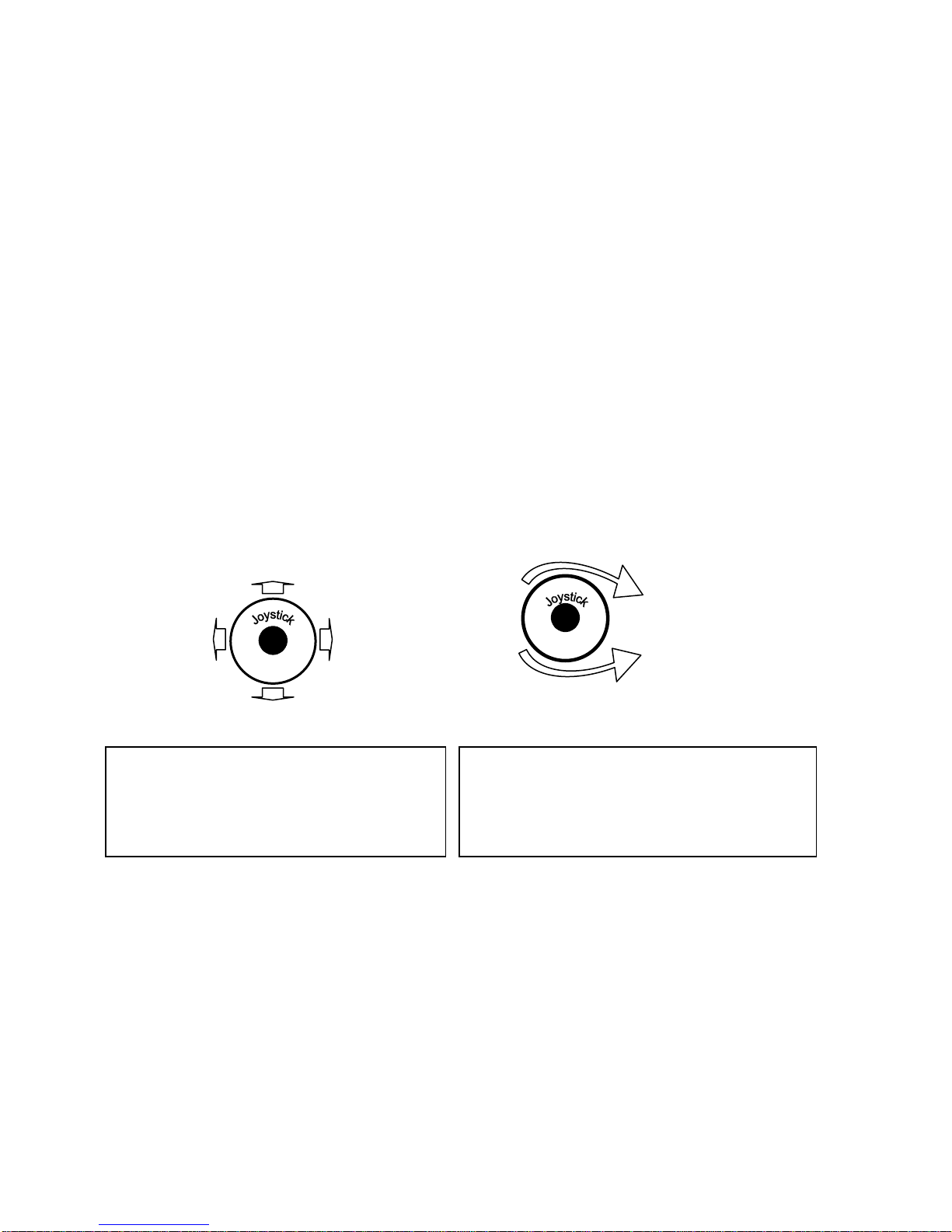
Up
Down
Left
Right
Zoom in
Zoom out
Rotate
The operation of the dome and the direction (up,
down, left and right) of the camera can be
controlled using the joystick of the keyboard
controller, as illustrated above.
Zoom control of the camera can be achieved by
rotating the knob on the joystick or by using TELE
(zoom in) and WIDE (zoon out) functions on the
keyboard controller as illustrated above.

19
4.5 Direct Input Commands for Dome Operation
The following preset position addresses are reference to the direct memory location of the dome
controller. They do not correspond to memory preset positions in the keyboard controller or software
applications that support PTZ preset functions. Please consult the manual of the chosen keyboard
controller for correct operation.
Dome preset memory locations: No. 1~50, 64 ~77 and 102~165
Special Function memory preset location: No.51~63, No.78~101.
The following commands are examples of direct Keyboard Entry from the keyboard controller
Select Dome ID 01: [1] + [ENTER] Keyboard Display: Dome ID:0001
Save preset position 01: [1] + [SHOT] + [ON] On Screen Display: Stored
Recall preset position 01: [1] + [SHOT] + [ACK]
Clear preset position 01: [2] + [SHOT] + [OFF]
[1]+ [SHOT] + [OFF]
Setting Auto Pan scanning between two points:The dome can conduct an auto Pan Scan between
two user preset points. You can operate the Tilt and Zoom controls at the same time without
interrupting the Auto Scan Motion.
Set Start Pan Position: [52] + [SHOT] + [ON]
Set End Pan Position: [53] + [SHOT] + [ON]
Setting the Pan speed: user needs to maintain a fixed manual scan speed for more than 3 seconds and
then press [51] + [SHOT] + [ACK] to save this speed as default Pan scan speed.
The dwell time of “starting point” and “ending point” of Pan scan is 2 seconds.
Start Auto Pan: [52] + [SHOT] + [ACK]
To Stop the Auto Scan move Joystick left or right.
You can resume Auto Scan by pressing again [52] + [SHOT] + [ACK]
Operating a preset tour: Auto point by point scan from preset point 1 to preset 16; (if a certain point
is not set or has been cleared, that point will not observed when “tour scan” is in progress.
The dwell time of each preset point in tour is 4 seconds.
Start Default Preset Tour : [51] + [SHOT] + [ON]
Please refer to the operation manual of keyboard control for the operation of the other six tour tracks.
To Stop the tour move the joystick of the controller in any direction “Pan” or “Tilt”.

20
Setting the Home position: This means the time duration before the dome positions itself to Preset
No.1 during a period of inactivity. (No keyboard control)
Start this function by pressing: [100] + [SHOT] + [ACK]
The time interval for returning to Home (preset 1) can be set from 1-2-4-8-10 minutes by pressing:
[95] + [SHOT] + [ACK] = 1 minute
[96] + [SHOT] + [ACK] = 2 minute
[97] + [SHOT] + [ACK] = 4 minute
[98] + [SHOT] + [ACK] = 8 minute
[99] + [SHOT] + [ACK] = 10 minutes
To disable the return to Home Position function press: [100] + [SHOT] + [ON]
Intelligent three-dimension tour scan setting: If a user wishes to monitor an area in continuous Pan
Scan Mode at a specific speed, they only need to maintain the scan speed steady for more than 3
seconds in a continuous pan direction and then press [101] + [SHOT] + [ACK] to continue auto
panning at the same speed.
At the same time, the user can operate the tilt and zoom movements independently.
Table of contents


