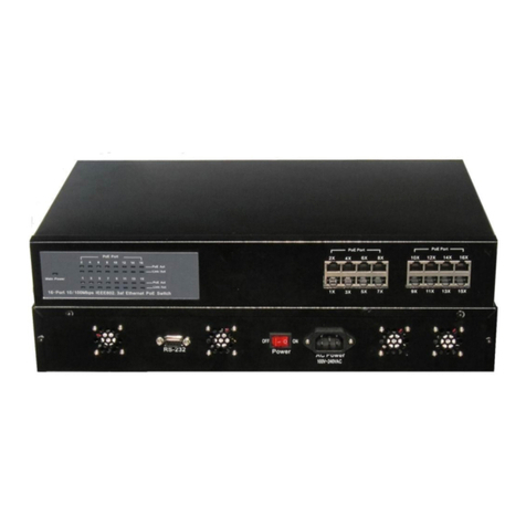
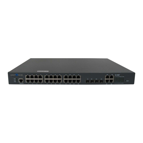
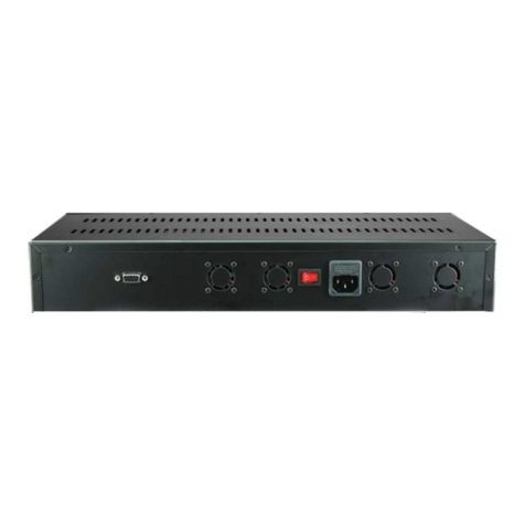
Securitytronix ST-POE-S16-200W User manual

v1.0 10/14/10
1
INSTALLATION MANUAL©
ST-POE-S16-200W
16-Port 10/100 Ethernet PoE Switch
Copyright North American Cable Equipment, Inc.

v1.0 10/14/10
2
PACKAGE CONTENTS
This package contains:
One ST-POE-S16-120W Power over Ethernet switch
One AC power cord
One mounting kit (two brackets with screws)
Four rubber feet
One installation manual
PRODUCT DESCRIPTION
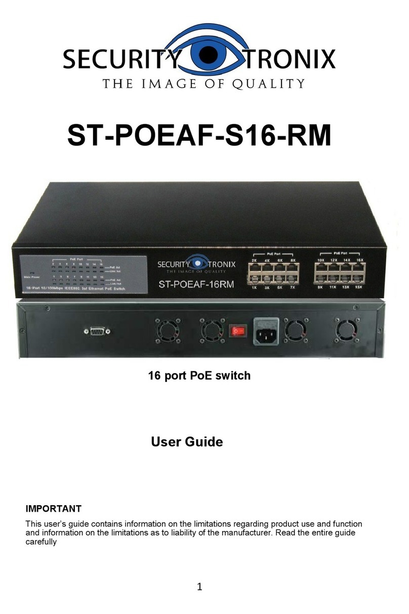
The ST-POE-S16-200W is a16-port 10/100Mbps Ethernet switch combined a with a standard
802.3af 16-port PoE capability. The unit incorporates an external 48VDC power supply. Each of
the PoE Ethernet ports can provide 15.4 watts of power as well as 10/100Mbps data transmission
over as CAT 5/ 5e /6 cables.
The ST-POE-S16-200W is a Power Source Equipment (PSE) and fully compatible with Powered
Devices (PD) that comply with the IEEE 802.3af PoE standard. The device enables users
to attach IEEE802.3af compliant devices such as wireless Access Points (APS), VOIP phone,
IP camera, printer and Network Attached Storage (NAS) directly to the unit without requiring
additional power on the network. The ST-POE-S16-200W was designed with home and small
business users in mind and is deal for installations where AC power is not available or not
cost-effective.
No configuration is required and installation is quick and easy. Support for Auto –MDI / MDI-X on
all of the ports eliminates the need for crossover connection to another switch or HUB.
Auto-Negotiation on each port senses the link speed of a network device (either 10 or 100) and
intelligently adjusts for compatibility and optimal performance.
This unit is designed for indoor use only.
FCC Warning
This device has been tested and found to comply with the regulations for Class B digital equipment
pursuant to Part 15 of FCC Rules. These limits are designed to provide reasonable protection
against harmful interference when the equipment is operated in a commercial environment. This
equipment generates, uses, and can radiate radio frequency energy and, if not installed and used
in accordance with users guide, may cause harmful interference to radio communications.
Operation of this device in a residential area is likely to cause harmful interference, in which case
the user will be required to correct the interference at his/her own expense.
UL Warning
Elevated Operating Ambient Temperature – If installed in a closed or multi-unit rack assembly, the
operating ambient temperature of the rack environment may be greater than the room’s ambient
temperature. Therefore, consideration should be given to installing the equipment in an
environment compatible with manufacturer’s maximum rated ambient temperature.
Reduced Air Flow – Installation of equipment in a rack should be such that the amount of airflow
required for safe operation of the equipment is not compromised.
Mechanical Loading – Rack mounting should be done to prevent any hazardous conditions
associated with uneven/unbalanced loading.
v1.0 10/14/10
3
SPECIFICATIONS
ST-POE-S16-200W
Specifications (Typical)
1. Standard
IEEE 802.3 10Base-T Ethernet
IEEE 802.3u 100Base-TX Fast Ethernet
IEEE 802.3x Full Duplex Flow Control
IEEE 802.3af Power over Ethernet
2. Protocol
CSMA/CD
3. Data Transfer Rate
Ethernet: 10Mbps (half-duplex), 20Mbps (full-duplex)
Fast Ethernet: 100Mbps (half-duplex), 200Mbps (full-duplex)
4. Network Cables
10BASE-T: 2-pair UTP CAT 3, 4, 5 up to 328 feet
100BASE-Tx: 2-pair UTP CAT 5, 5e up to 328 feet
5. Number of Ports
16x10/100Mbps auto-MDIX RJ-45 ports with16 PoE enabled ports
6. PoE Power on RF-45
Power +: ping 3 and ping 6; Power -: ping 1 and ping 2
7. AC to DC Power
Input 110V~240VAC, 50Hz ~ 60Hz. Output 48VDC @ 4.16A
8. Power Consumption
8.0 watts (max with no PD device connected)
192 watts (max with 16 PoE ports connected)
9. Humidity
Relative humidity 5% -95%
10. EMI
FCC Class B, CE Mark Class B
11. Safety
110VAC to 240VAC power supply UL listed
12. RAM Buffer
64K bytes per device
13. Filtering Address Table
1K entries per device
14. Packet Filtering/Forwarding Rate
10Mbps Ethernet: 14,880/pps; 10Mbps Ethernet: 148,800/pps
15. MAC Address Learning
Automatic Update
16. Transmission Method
Store-and-Forward
17. Dimensions
17”W x 10.4”D x 2.6”H
18. Operating Temperature
32°F ~ 104°F
INSTALLATION AND OPERATION
1. UNPACKING and HANDLING
Each unit is shipped assembled and factory tested.
Ensure that all accessories are removed from the container before discarding packing material
2. MECHANICAL INSPECTION
Inspect the front and rear of the equipment for shipping damage. Make sure the equipment is
clean, and no connectors are broken, damaged, or loose. If equipment appears to be
damaged or defective please contact your distributor or Securitytronix in the USA at
1-610-429-1511 for assistance.

v1.0 10/14/10
4
3. HARDWARE CONNECTIONS
The unit should be installed within 5 feet of the AC power outlet and on a surface capable of
supporting the device’s 13.2 lbs weight. Objects are not to be placed on the device and there
must be sufficient space and ventilation for proper heat dissipation.
Front Panel Description
Ports
Ports 1X through 16X –A standard 10/100Mbps Ethernet ports supporting 10Mbps
Ethernet or 100Mbps Fast Ethernet. The port runs in both half and full duplex modes
using two pair of CAT 5/5e cable.
PoE Port 1X through PoE Ports 16X –These ports support 10/100Mbps Ethernet in
addition to 802.3af Power Over Ethernet. All PoE ports will automatically activate
when a compatible terminal is connected. The device will supply power through the
Ethernet port to the connected PoE Device (PD). The unit also supports legacy
devices allowing users to mix legacy and PoE compatible equipment on the same
network.
All ports are Auto-MDI. As the device can auto negotiate to MDII or MDI-X, the CAT
cable can be connected regardless of whether it is a standard or crossover cable.
LED Status Indicators
The LEDs provide instant status feedback and provides assistance when troubleshooting is
required.
Power LED
LED “On”: Power is on; LED “OFF”: Power is off
LINK/ACT
LED “On”: Specific port is linked and active.
LED “OFF”: Specific port is not connected or inactive
PoE LED (1 – 16)
LED “On”: The PoE Power Device (PD) is connected and the port is
successfully supplying power.
LED “Off”: No PoE Power Device (PD) connected

v1.0 10/14/10
5
Rear Panel Description
Desktop Installation
If installing the ST-POE-S16-200W on a desktop or shelf place the included rubber feet on the
bottom of the unit (one per corner) to provide cushioning and reduce the possibility of
scratching furniture.
19” Rack Installation
Fasten the two included mounting brackets to the ST-POE-S16-200W using the screws
provided. With the brackets attached securely, mount the unit in a standard EIA 19” rack as
shown below.

v1.0 10/14/10
6
Cable Connections
a. Connect the AC power cord to the unit and then to an appropriately rated AC power
outlet. Move the unit’s power switch to the “On” position.
b. As required connect a CAT5/5e or CAT 6 network cable from the network device to
any of the ST-POE-S16-200W’s available RJ-45 ports.

v1.0 10/14/10
7
4. TROUBLESHOOTING
a. Make sure all component and cable connections are tight and not loose.
b. When connecting a computer to the ST-POE-S16-200W if the Link/ACT LED turns on
but the 100Mbps LED remains off the computer’s connection speed is 10Mbps.
c. If unable to share files once the computer is connected to the ST-POE-S16-200W (i)
check to see if the Link/ACT LED is on; (ii) measure the network cable to ensure the
minimum and maximum lengths are respectively 5 feet and 328 feet; (iii) disable any
software firewall program and (iv) verify that file sharing is enabled via the computer’s
operating system.
d. Ensure the CAT wire connections on the switch and connected devices are using the
same pins and the data wires the correct polarities.
e. The quality of CAT cables has a major effect on the usable distance of transmission
lines and the quality of the displayed signal. Therefore, the actual transmission length
is subject to the quality of the CAT cables being used. Professional grade
transmission lines should be used.
f. If your device is not displaying a video signal check to be sure the transmitter and
receiver each have power. Then check all wire connections for tight fit and correct
polarity.
g. If interference appears on the image check all system connections including camera,
housing, monitor, DVR, etc. as well as ensuring all devices are property grounded.
h. If the image appears twisted or wobbly make sure the wire connections on the
transmitter and receiver have the same polarities. Also check the CAT cable
connections to the RJ-45 connectors are in the correct order.
i. If power is getting to the remote camera but PTZ controls are not functioning correctly
(i) make sure all control cables have tight connections at the remote camera and
controller and (ii) ensure the polarities for the control wires are consistent among the
between the remote camera and controller connections.
j. Further troubleshooting assistance can be found on-line at www.securitytronix.com in
addition to support from Securitytronix sales engineers at 1-610-429-1511.
Table of contents
Other Securitytronix Switch manuals

Securitytronix
Securitytronix ST-POEAF-24UL-RM User manual

Securitytronix
Securitytronix ST-POEAF-8-RM User manual

Securitytronix
Securitytronix ST-POE16 User manual

Securitytronix
Securitytronix ST-POE24M User manual

Securitytronix
Securitytronix ST-POEAF-S04 User manual

Securitytronix
Securitytronix ST-POE-S04-60W User manual

Securitytronix
Securitytronix ST-POEAF-4/8 User manual

Securitytronix
Securitytronix ST-POEAF-S08 User manual

Securitytronix
Securitytronix ST-POE16 User manual

Securitytronix
Securitytronix ST-POEAF-S16-RM User manual