SEDEMAC CB12XX SERIES User manual

MANUAL FOR
CB12XX SERIES
BATTERY
CHARGERS
Product Manual Version #1.00
ABSTRACT
This manual is intended
as an Information guide
for operating SEDEMAC's
CB12XX series battery
chargers
Doc # SED-MAN-CB12XX-002
Date: 11-Sep-2017

Copyright
All rights reserved. No part of this publication may be reproduced, distributed or transmitted
by any means (including photocopying or storing in any medium by electronic means or other)
without the prior written permission of the copyright holder. Any reference to trademarked
product names used within this publication is owned by their respective companies.
SEDEMAC Mechatronics Pvt. Ltd. reserves the right to change the contents of this document
without prior notice. For permission requests and applications to reproduce any part of this
publication should be addressed to SEDEMAC Mechatronics Pvt. Ltd at below mentioned
contact details.
SEDEMAC Mechatronics Pvt. Ltd.
C9-10, C Block, MIDC Bhosari
Pune 411026, INDIA
Web Support:
Email: support@sedemac.com
Website: www.sedemac.com
Telephonic Support:
+91-20-67313500
+91-8551039888
+91-8551041888
+91-8551043888
SEDEMACTM
Format No: SED-OHA-QF-06, Rev 01
NOTE: This document is a property of SEDEMAC Mechatronics Pvt. Ltd. It shall not be communicated to or copied by anyone without the written permission of the company.
This document is controlled when it is printed.
Page 1 of 19
Safety Instructions
General Instructions
✓This document includes important instructions that should be followed during installation and
maintenance of the Generator Set controller.
✓For safety reasons, the manufacturer recommends that this equipment be installed and serviced by
an Authorized Service personnel. Follow all applicable state and local electrical codes.
✓Efficient and safe operation of the controller can be acquired only if the equipment is correctly
operated and maintained. Many accidents arise due to ignorance or illiteracy towards the elemental
rules of safety and precautions.
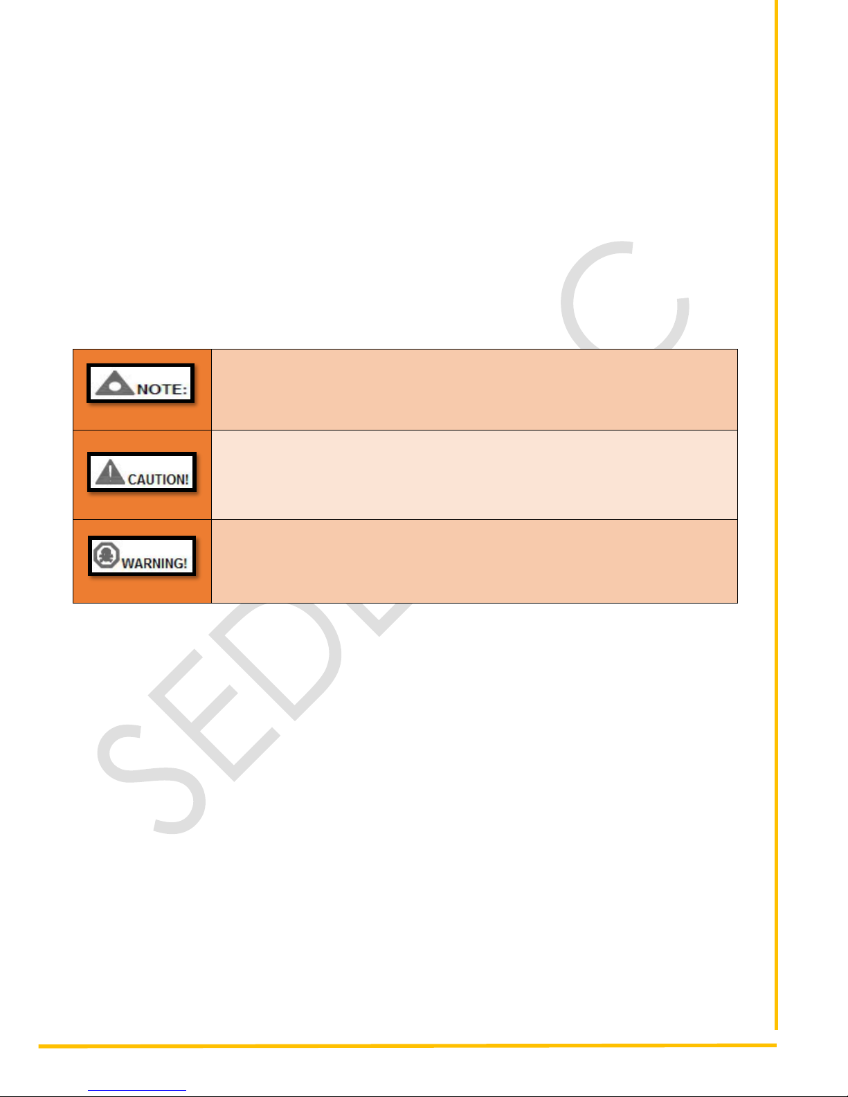
The following safety notations found throughout this document indicate potentially hazardous conditions to the
operator, service personnel or the equipment.
•Highlights an essential element of a procedure to ensure correctness
•Indicates a procedure or practice, which, if not strictly observed, could result
in damage or destruction of equipment
•Indicates a procedure or practice, which could result in injuring personnel or
loss of life, if not followed correctly
Electrical safety
✓Electric shock can cause severe personal injury or death.
✓Ensure the generator set must be grounded before performing any installation or service.
✓Generators produce high electrical voltages direct contact with it can cause fatal electrical shock.
Prevent contact with terminals, bare wires, connections, etc., while the generator and related
equipment are running. Do not tamper with interlocks.
✓To handle the maximum electrical current, sizes of wire gauge used for electrical connections and
wirings must be appropriate to which they will be subjected to.
•
In operation safety
✓Before installing Genset controller, ensure that all power voltage supplies are positively turned off at
their source. Disconnect the generator’s battery cables and remove panel fuse to prevent accidental
start up. Disconnect the cable from the battery post, indicated by a NEGATIVE, NEG, or (–) first.
Reconnect the negative cable last. Failure to do so will result in hazardous and possibly fatal electrical
shock.
✓Remove electric power supply before removing controller or touching other electrical parts.
✓Use extreme caution when working on electrical components. High voltage can cause injury or death.
✓Use rubber insulative mats placed on dry wood platforms over floors that are metal or concrete when
working near Generator set or other electrical equipment.

SEDEMACTM
Format No: SED-OHA-QF-06, Rev 01
NOTE: This document is a property of SEDEMAC Mechatronics Pvt. Ltd. It shall not be communicated to or copied by anyone without the written permission of the company.
This document is controlled when it is printed.
Page 2 of 19
✓Do not wear damp clothing (Particularly wet shoes) or allow skin surface to be damp when handling
electrical equipment.
✓Do not operate any electrical device or wires while standing in water, while barefoot, or while hands or
feet are wet. IT MAY RESULT IN SEVERE ELECTRICAL SHOCK.
✓Do not wear jewellery. Jewellery can cause a short circuit within electrical contacts and cause shock
or burning.
✓In case of an accident caused by electric shock, immediately shut down the electrical power source. If
this is not possible, try to release the victim from the live conductor. AVOID DIRECT CONTACT WITH
THE VICTIM. Use a nonconducting object, like, a rope or wooden stick, to release the victim from the
live conductor. If the victim is unconscious, apply first aid and get immediate medical help.

SEDEMACTM
Format No: SED-OHA-QF-06, Rev 01
NOTE: This document is a property of SEDEMAC Mechatronics Pvt. Ltd. It shall not be communicated to or copied by anyone without the written permission of the company.
This document is controlled when it is printed.
Page 3 of 19
List of Abbreviation
This list contains the list of acronyms used in this document and it can be used to refer their respective
description. This List Does not contain units of measure.
Acronym
Description
AC
Alternating Current
ACK
Acknowledge
ALT
Alternator
AMF
Auto Mains Failure
AUX
Auxiliary
BTS
Base Transceiver Station
CHG
Charging
CKT
Circuit
CT Ratio
Current Transformer Ratio
DC
Direct Current
DG
Diesel Generator
DIG IN
Digital Input
ENG TEMP
Engine Temperature
GCU
Genset Control Unit
Genset
Generator Set
GND
Ground
HMI
Human Machine Interface
HSD
High Side Driver
HWT
High Water Temperature
LCD
Liquid Crystal Display
LED
Light Emitting Diode
LLOP
Low Lube Oil Pressure
LOP
Lube Oil Pressure
LVL
Level
MCP
Manual Control Panel
MPU
Magnetic Pickup Unit
OV
Over Voltage
PID
Proportional Integral Derivative
PWM
Pulse Width Modulation
RMS
Root Mean Square
RPM
Revolutions Per Minute
R-Y-B
Red-Yellow-Blue
SCP
Sensor Common Point
SMD
State Machine Diagram
TEMP
Temperature
USB
Universal Serial Bus
UV
Under Voltage

SEDEMACTM
Format No: SED-OHA-QF-06, Rev 01
NOTE: This document is a property of SEDEMAC Mechatronics Pvt. Ltd. It shall not be communicated to or copied by anyone without the written permission of the company.
This document is controlled when it is printed.
Page 4 of 19
Table of Contents
1Introduction..........................................................................................................................7
1.1 Key Highlights of the Product ..........................................................................................7
1.2 Product Variants..............................................................................................................7
2Charging Principle...............................................................................................................7
3Modes of Operation .............................................................................................................8
4Installation............................................................................................................................8
4.1 Pin Terminal Description..................................................................................................8
4.2 Connection Procedure ....................................................................................................8
4.3 Dimensions .....................................................................................................................9
4.4 Mounting on Panel ........................................................................................................12
4.5 Status Indication LEDs..................................................................................................12
5Specification and Parameters...........................................................................................13
6Efficiency Curve.................................................................................................................14
7Troubleshooting.................................................................................................................15
8Applicable Standards ........................................................................................................15
Notes .........................................................................................................................................16

SEDEMACTM
Format No: SED-OHA-QF-06, Rev 01
NOTE: This document is a property of SEDEMAC Mechatronics Pvt. Ltd. It shall not be communicated to or copied by anyone without the written permission of the company.
This document is controlled when it is printed.
Page 5 of 19
List of Figures
Figure 1: Charging characteristics graph..................................................................................................7
Figure 2: Pin terminals of CB12XX...........................................................................................................8
Figure 3: CB1205 Front View .................................................................................................................10
Figure 4: CB1205 Side view...................................................................................................................10
Figure 5: CB1205 Top view....................................................................................................................10
Figure 6: CB1210 front view...................................................................................................................11
Figure 7: CB1210 side view ...................................................................................................................11
Figure 8: CB1210 top view.....................................................................................................................11
Figure 9: Mounting holes in CB12XX (Front view)..................................................................................12
Figure 10: Status indication LEDs in CB12XX........................................................................................12
Figure 11: Efficiency Curve (Efficiency vs Input AC voltage) for CB1205 ...............................................14
Figure 12: Efficiency Curve (Efficiency vs Input AC voltage) for CB1210 ...............................................14

SEDEMACTM
Format No: SED-OHA-QF-06, Rev 01
NOTE: This document is a property of SEDEMAC Mechatronics Pvt. Ltd. It shall not be communicated to or copied by anyone without the written permission of the company.
This document is controlled when it is printed.
Page 6 of 19
List of Tables
Table 1: Mounting Information parameters for CB1205 and CB1210 .......................................................9
Table 2: Modes Indication of CB12XX....................................................................................................13
Table 3: Specifications and parameters for CB12XX..............................................................................13
Table 4: Possible faulty conditions, causes and their remedial actions...................................................15
SEDEMACTM
Format No: SED-OHA-QF-06, Rev 01
NOTE: This document is a property of SEDEMAC Mechatronics Pvt. Ltd. It shall not be communicated to or copied by anyone without the written permission of the company.
This document is controlled when it is printed.
Page 7 of 19
1 Introduction
This document describes necessary information for operating SEDEMAC's CB12XX series battery
chargers. It is specially designed to meet the charging characteristics of lead acid genset batteries. The
chargers comprise of high grade electronic components to ensure reliable and efficient performance.
1.1 Key Highlights of the Product
•Automated three stage battery charging features is provided to ensure longer battery life
•Advanced switch mode supply design is responsible for higher output efficiency (>85%)
•Manual boost mode feature results in fast charging
•Built-in current and voltage protection circuit which gives effective protection against input over
voltage, short circuit, output over current, reverse battery protection, Input under-voltage
shutdown, etc.
•LEDs for status diagnostic support
•Can be used as Switched Mode Power Supply (SMPS) in manual boost mode
1.2 Product Variants
•CB1205 (Suitable for 12V lead acid battery with rated current 5A)
•CB1210 (Suitable for 12V lead acid battery with rated current 10 A)
2 Charging Principle
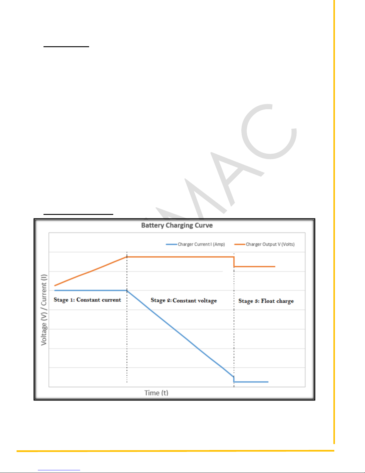
Figure 1: Charging characteristics graph
SEDEMACTM
Format No: SED-OHA-QF-06, Rev 01
NOTE: This document is a property of SEDEMAC Mechatronics Pvt. Ltd. It shall not be communicated to or copied by anyone without the written permission of the company.
This document is controlled when it is printed.
Page 8 of 19
Battery Life depends on the battery charging method. To ensure long battery life, Three-Stage Charging
method is used. This method is described in the above charging characteristics graph.
•Constant Current (CC) Stage – When the battery terminal voltage falls below a pre-defined
threshold value, the charging current is constant. In this stage, the voltage rises at constant
current to reach the threshold value.
•Constant Voltage (CV) Stage – Once the battery terminal voltage reaches the pre-defined
threshold value, charging current starts to drop at constant voltage. The current drops to a pre-
defined threshold value.
•Float Charge Stage – In this stage, the battery terminal voltage needs to be constant at optimum
value. To achieve this, the battery is charged continuously. The float charge thus compensates
any loss caused by self-discharge and keeps the battery fully charged.
3 Modes of Operation
As per the amount of charging current consumed by battery the charger output is operated in different
modes. There are three modes of operations.
•Auto boost mode: When the charging current is greater than certain value (2A for CB1210 and
1A for CB1205), the charger’s output voltage is maintained at 13.7V.
•Float mode: When the charging current is less than certain value (2A for CB1210 and 1A for
CB1205), the charger’s output voltage is maintained at 13.2V.
•Manual boost mode: The charger’s output voltage is 14.4V and is independent of the amount
of current drawn (internally limited i.e. 10A for CB1210 and 5A for CB1205) by the battery.
4 Installation
4.1 Pin Terminal Description
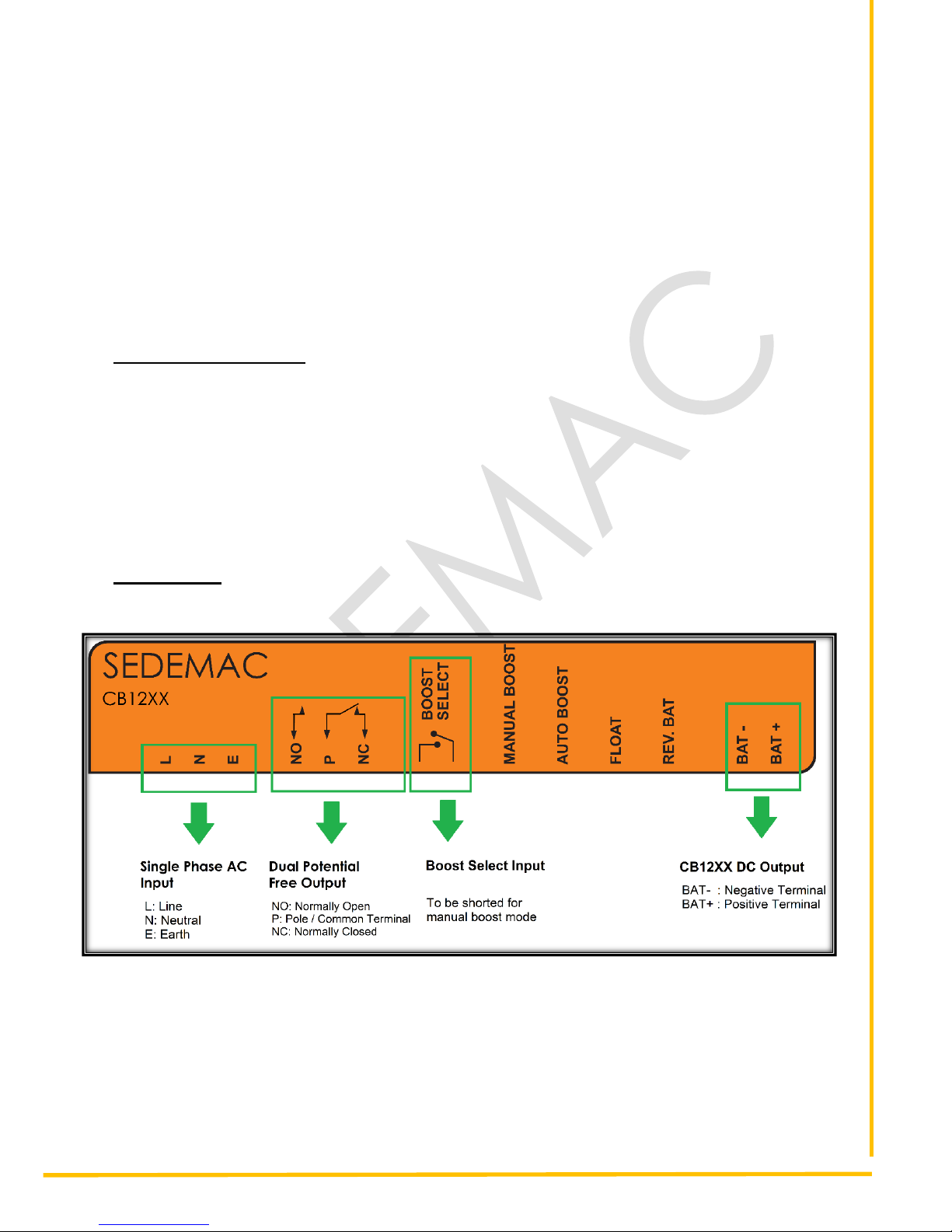
Figure 2: Pin terminals of CB12XX
4.2 Connection Procedure
•Connect terminals L, N and E to AC mains (110V – 290V) using 0.75 mm2 multi strand copper
wire.
•Connect BAT+ and BAT- to positive and negative terminals of battery respectively using 2.5

SEDEMACTM
Format No: SED-OHA-QF-06, Rev 01
NOTE: This document is a property of SEDEMAC Mechatronics Pvt. Ltd. It shall not be communicated to or copied by anyone without the written permission of the company.
This document is controlled when it is printed.
Page 9 of 19
mm2 multi strand copper wire.
•Connect positive terminal of an external source (AC/DC) to the pole terminal of the battery
charger. Connect NO terminal of battery charger to one terminal of the indicator device and
other to the ground terminal of the external source (AC/DC) to detect the absence of AC mains.
•In order to operate the charger in manual boost mode, short the terminals of “Boost select” by
means of a wire.
The recommended torque while tightening screws at the connecting
terminals is 0.4 to 0.5 N-m.
4.3 Dimensions
4.3.1 Mounting Information
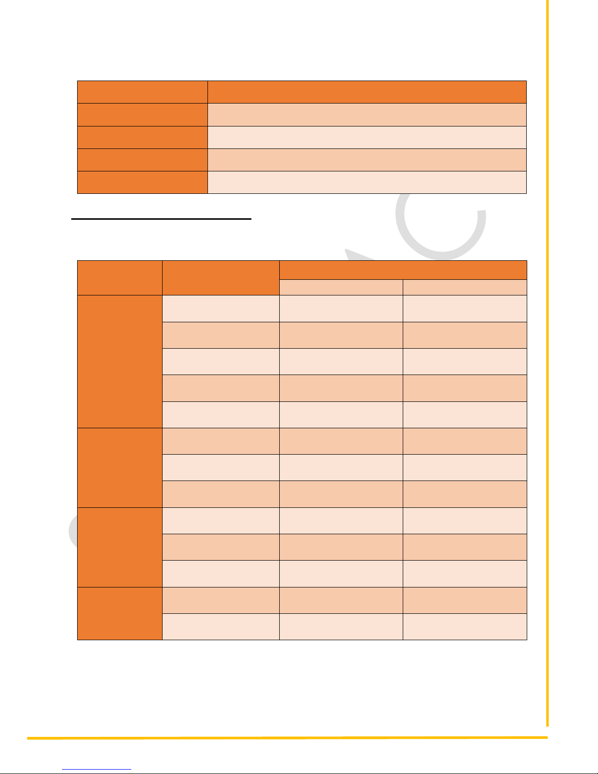
Below table gives the brief information about the battery charger mounting for both variants.
Table 1: Mounting Information parameters for CB1205 and CB1210
Parameter
Comments
CB1205
CB1210
Overall Size
165mm X 119mm X67mm
192mm X 129mm X67mm
Mounting type
Panel mounting
Panel mounting
Mounting hole centres
154.6mm X 40mm
181.6mm X 40mm
Mounting holes
Holes M4
Holes M4
Recommended Screw
M4
M4
Recommended Torque
0.8 Nm to 1 Nm
0.8 Nm to 1 Nm
Over tightening of the screws may damage the charger casing.

SEDEMACTM
Format No: SED-OHA-QF-06, Rev 01
NOTE: This document is a property of SEDEMAC Mechatronics Pvt. Ltd. It shall not be communicated to or copied by anyone without the written permission of the company.
This document is controlled when it is printed.
Page 10 of 19
4.3.2 CB1205 Case Dimension
Figure 3: CB1205 Front View
Figure 4: CB1205 Side view
Figure 5: CB1205 Top view

SEDEMACTM
Format No: SED-OHA-QF-06, Rev 01
NOTE: This document is a property of SEDEMAC Mechatronics Pvt. Ltd. It shall not be communicated to or copied by anyone without the written permission of the company.
This document is controlled when it is printed.
Page 11 of 19
4.3.3 CB1210 Case Dimension
Figure 6: CB1210 front view
Figure 7: CB1210 side view
Figure 8: CB1210 top view
SEDEMACTM
Format No: SED-OHA-QF-06, Rev 01
NOTE: This document is a property of SEDEMAC Mechatronics Pvt. Ltd. It shall not be communicated to or copied by anyone without the written permission of the company.
This document is controlled when it is printed.
Page 12 of 19
4.4 Mounting on Panel
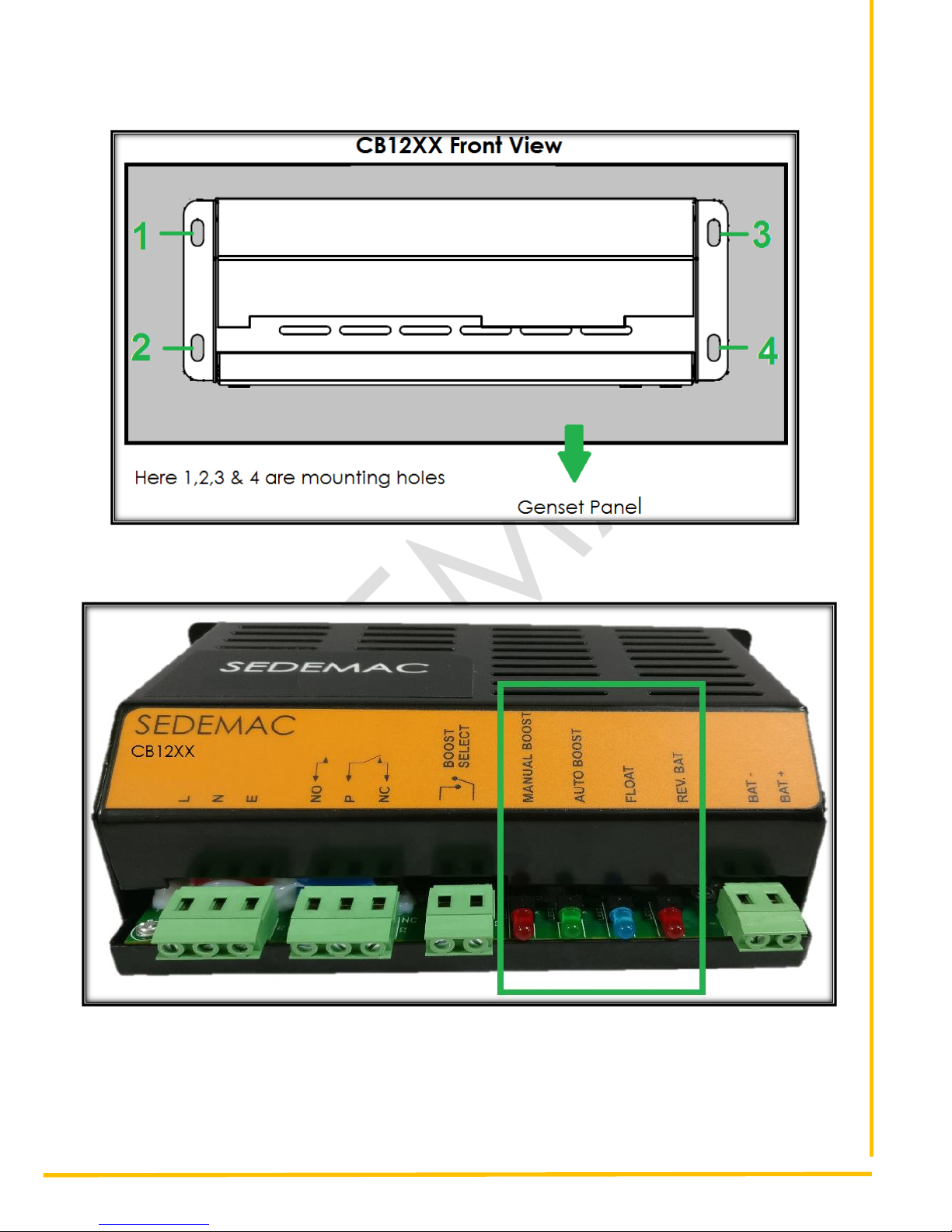
Figure 9: Mounting holes in CB12XX (Front view)
4.5 Status Indication LEDs
Figure 10: Status indication LEDs in CB12XX
SEDEMACTM
Format No: SED-OHA-QF-06, Rev 01
NOTE: This document is a property of SEDEMAC Mechatronics Pvt. Ltd. It shall not be communicated to or copied by anyone without the written permission of the company.
This document is controlled when it is printed.
Page 13 of 19
Table 2: Modes Indication of CB12XX
LED colours
Status Indication
RED (Leftmost)
Manual boost mode
GREEN
Auto boost mode
BLUE
Float boost mode
RED (Rightmost)
Reverse battery mode
5 Specification and Parameters
Following table gives a brief overview of CBXX battery charger specifications
Table 3: Specifications and parameters for CB12XX
Bulletins
Contents
Parameters
CB1205
CB1210
Input
Characteristics
Nominal input AC
voltage range
110V AC to 290V AC
110V AC to 290V AC
Max. input AC voltage
range
90V AC to 305V AC
90V AC to 305V AC
AC frequency range
48 Hz to 62 Hz
48 Hz to 62 Hz
Max. input current
1.4 Amp
2.5 Amp
Efficiency
>85%
>85%
Output
Characteristics
Max. output power
72 Watt
144 Watt
Max. charging current
5 A (Tolerance ±1%)
10 A (Tolerance ±1%)
No load output voltage
13.2 V DC
13.2 V DC
Operating
conditions
Working temperature
range
-300 C to 600 C
-300 C to 600 C
Storage temperature
range
-300 C to 850 C
-300 C to 850 C
Humidity
0% to 95% RH at 400 C
0% to 95% RH at 400 C
Shape and size
Weight
~0.9 kg
~1.2 kg
Dimension
165mm X 119mm X67mm
192mm X 129mm X67mm
SEDEMACTM
Format No: SED-OHA-QF-06, Rev 01
NOTE: This document is a property of SEDEMAC Mechatronics Pvt. Ltd. It shall not be communicated to or copied by anyone without the written permission of the company.
This document is controlled when it is printed.
Page 14 of 19
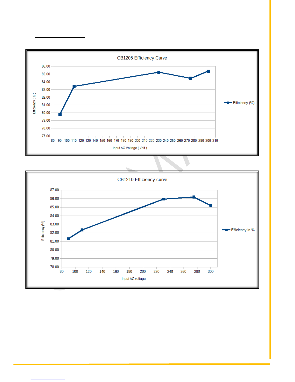
6 Efficiency Curve
Figure 11: Efficiency Curve (Efficiency vs Input AC voltage) for CB1205
Figure 12: Efficiency Curve (Efficiency vs Input AC voltage) for CB1210

SEDEMACTM
Format No: SED-OHA-QF-06, Rev 01
NOTE: This document is a property of SEDEMAC Mechatronics Pvt. Ltd. It shall not be communicated to or copied by anyone without the written permission of the company.
This document is controlled when it is printed.
Page 15 of 19
7 Troubleshooting
Following table discuss about the common faults or errors observed during operation and possible
causes and remedies to overcome.
Table 4: Possible faulty conditions, causes and their remedial actions
Sr.
No.
Possible faulty
conditions
Possible causes
Remedial actions
1.
Continuously switching
between Blue and
Green LEDs
•Battery charger’s
output short circuit
•Check the output terminal
connections
2
Red led (Rightmost) is
ON
•Reverse connection of
battery charger output
with battery (BAT+
connected to -ve
terminal of battery and
vice versa)
•Check the output terminal
connections with battery
terminals
3
Mains failure indicator
(externally connected
bulb, LED, etc.)
connected across NO
terminal is off
•Absence of AC mains
supply
•Wrong connection of
input terminals (L,N,E)
of supply with the
battery charger
•Check the presence of
mains
•Check the input terminal
connections
8 Applicable Standards
•EMI/EMC Standards: IEC 61000-6-2, IEC 61000-4-4, IEC 61000-4-5
•Environmental Standards: IEC 60068-2-1, IEC 60068-2-2, IEC 60068-2-6, IEC60068-2-78,
IEC60068-2-30,IEC 60068-2-27

SEDEMACTM
Format No: SED-OHA-QF-06, Rev 01
NOTE: This document is a property of SEDEMAC Mechatronics Pvt. Ltd. It shall not be communicated to or copied by anyone without the written permission of the company.
This document is controlled when it is printed.
Page 16 of 19
Notes
SEDEMACTM
Format No: SED-OHA-QF-06, Rev 01
NOTE: This document is a property of SEDEMAC Mechatronics Pvt. Ltd. It shall not be communicated to or copied by anyone without the written permission of the company.
This document is controlled when it is printed.
Page 17 of 19
Disclaimer: Due to continuous development, the details provided in this document are subject
to change without any prior notice.
SEDEMAC Mechatronics Pvt Ltd
Technical Centre
C9-10, C Block, MIDC Bhosari
Pune 411026, India
Manufacturing Plant
G-1, MIDC, Phase-III Chakan
Industrial Area, Nighoje
Pune 410501, India
Manufacturing Plant
Survey No. 64/5, Off Sinhagad Road
Vadgaon Budruk, Narhe
Pune 411041, India
Table of contents


