nor-tec UL60 User manual
OPERATION MANUAL
Part-No: 315 016 002 001
Issue: 04 / 2018
Batter Charger /Anal zer
UL60
0.5 – 40VDC / 0.5 – 60A
Part-No.: UL60.040000
NSN.: 6625-12-398-1233
Software-Version UL60 V1.40
Date: 04.04.2018
CO YRIGHT
©
2014-2018 by
Nortec Electronics GmbH & Co. KG
An der Strusbek 32B
D – 22926 Ahrensburg
hone: +49 4102 42002
Fax: +49 4102 42840
Email: [email protected]
Web: www.nortec-electronics.de

1 General information
2 © Nortec Electronics 2018

1 General information
© Nortec Electronics 2018 3

1 General information
4 © Nortec Electronics 2018
HISTORY OF REVISION
Date
Modification
Version
04.04.2018
I
-
Charge Capacit
Monitoring
1.40
Manufacturer: Nortec Electronics GmbH & Co. KG
An der Strusbek 32 B
22926 Ahrensburg
art-No.: 315 016 002 001
Edition: 04 / 2018
Date: 04.04.2018
© Copyright
This document and all contained information are property of Nortec Electronics GmbH & Co. KG.
Nortec Electronics GmbH & Co. KG reserves the right to make product changes without prior no-
tice.

1 General information
© Nortec Electronics 2018 5

1 General information
6 © Nortec Electronics 2018
Table of content
1
General information .................................................................................... 10
1.1 Scope of application ............................................................................................ 10
1.2 Application ........................................................................................................... 11
2
Maintenance and safet instructions ........................................................ 12
2.1 Safet instructions ............................................................................................... 12
2.2 Maintenace instructions ...................................................................................... 15
3
Operating and displa elements ................................................................ 16
3.1 Front panel ........................................................................................................... 16
3.2 Rear Panel ............................................................................................................ 17
4
Principles of operation ............................................................................... 19
4.1 Connection activities ........................................................................................... 19
4.2 Installation ............................................................................................................ 19
4.3 Warning notes ...................................................................................................... 19
5
Technical data ............................................................................................. 20
5.1 Electrical input and output parameter ................................................................ 20
5.2 Temperature range ............................................................................................... 20
5.3 Calibration ............................................................................................................ 20
6
Handling ...................................................................................................... 21
6.1 General handling instructions ............................................................................. 21
6.1.1 Display ................................................................................................................... 21
6.1.2 Keyboard ................................................................................................................ 22
6.2 Selftest .................................................................................................................. 23
6.3 USB ....................................................................................................................... 24
6.4 RS232 .................................................................................................................... 26
6.5 Remote monitoring .............................................................................................. 26
6.6 Network printer ..................................................................................................... 28
6.7 Functions of printer programs ............................................................................ 30
7
S stem preferences .................................................................................... 32
7.1 Language, date, time ............................................................................................ 32
7.1.1 Select language ..................................................................................................... 32
7.1.2 Change date .......................................................................................................... 33
7.1.3 Enter time ............................................................................................................... 33
7.2 Adjust Ethernet IP-address ................................................................................. 34
7.2.1 Enter I -address .................................................................................................... 34
7.2.2 Enter subnet mask ................................................................................................. 34
7.2.3 Adjust gateway ....................................................................................................... 35
7.2.4 MAC address ......................................................................................................... 35
7.2.5 Adjust network printer............................................................................................. 35
7.2.6 Device number ....................................................................................................... 36
7.3 Calibration / Unit number, .................................................................................... 36
8
Program selection ...................................................................................... 37
8.1 Principles for program selection ......................................................................... 37
8.2 The batter t pes ................................................................................................. 39
8.3 The program – Matrix ........................................................................................... 39
8.4 Batter data entr ................................................................................................. 40
8.4.1 General information ................................................................................................ 40
8.4.2 Work with „Other battery“ : 00 .............................................................................. 40
8.4.3 Work with lead batteries ......................................................................................... 41
8.4.4 Work with NiCd batteries ........................................................................................ 43
8.5 The displa screen for program 420 ................................................................... 45
8.5.1 rogram 420 Step 1 ............................................................................................... 45
8.5.2 rogram 420 Step 2 ............................................................................................... 46

1 General information
© Nortec Electronics 2018 7
8.5.3 rogram 420 Step 3 ............................................................................................... 47
8.5.4 rogram 420 Step 4 ............................................................................................... 48
8.5.5 rogram 420 Step 5 ............................................................................................... 49
8.5.6 rogram 420 Step 6 ............................................................................................... 50
9
Tabular overview of the program procedures .......................................... 51
9.1 Discharge .............................................................................................................. 52
9.1.1 rogram 000: Discharge (without data specification of a battery) ........................... 53
9.1.2 rogram 010: Discharge b battery sealed MIL ..................................................... 53
9.1.3 rogram 011: Discharge b battery sealed commercial ......................................... 54
9.1.4 rogram 016: Discharge b battery vented commercial ......................................... 54
9.1.5 rogram 019: Discharge b battery (free input) ..................................................... 55
9.1.6 rogram 020: Discharge NiCd battery (manufacturer independent) ....................... 55
9.1.7 rogram 021: Discharge NiCd battery HAWKER ................................................... 56
9.1.8 rogram 022: Discharge NiCd battery SAFT .......................................................... 56
9.1.9 rogram 023: Discharge to 23 V NiCd battery NKBN ............................................. 57
9.2 Initial commissioning ........................................................................................... 58
9.2.1 rogram 110: Initial commissioning b battery sealed MIL .................................... 58
9.2.2 rogram 111: Initial commissioning b battery sealed commercial ........................ 59
9.2.3 rogram 116: Initial commissioning b battery vented commercial ........................ 60
9.2.4 rogram 120: Initial commissioning NiCd battery (manufacturer independent) ....... 61
9.2.5 rogram 121: Initial operation NiCd battery HAWKER ........................................... 62
9.2.6 rogram 124: Initial operation NiCd battery MARATHON ....................................... 63
9.3 Charge .................................................................................................................. 65
9.3.1 rogram 210: Charge b battery sealed MIL ......................................................... 66
9.3.2 rogram 211: Charge b battery sealed commercial ............................................. 68
9.3.3 rogram 212: Charge Valve Regulated Lead Acid Aircraft Battery ......................... 69
9.3.4 rogram 216: Charging lead battery commercial open ........................................... 70
9.3.5 rogram 217: Charge b battery MIL 3-C Orion .................................................. 70
9.3.6 rogram 219: Charge b battery (free input) .......................................................... 71
9.3.7 rogram 220: Charge NiCd battery (manufacturer independent) ............................ 72
9.3.8 rogram 221: Charge NiCd battery HAWKER ........................................................ 73
9.3.9 rogram 222: Charge NiCd battery SAFT .............................................................. 74
9.3.10 rogram 223: Charge NiCd battery NKBN ............................................................. 75
9.3.11 rogram 224: Charging NiCd battery MARATHON ................................................ 76
9.4 Capacit test ......................................................................................................... 78
9.4.1 rogram 312: Capacity Test Valve Regulated Lead Acid Aircraft Battery ............... 78
9.4.2 rogram 321: Capacity Test NiCd battery HAWKER .............................................. 80
Discharging maximum 90 minutes. ........................................................................................ 80
9.4.3 rogram 322: Capacity Test NiCd battery SAFT .................................................... 82
9.4.4 rogram 323: Capacity Test NiCd battery NKBN ................................................... 83
9.4.5 rogram 324: Capacity Test NiCd battery MARATHON ......................................... 84
9.5 Maintenance ......................................................................................................... 85
9.5.1 rogram 410: Maintenance b battery sealed MIL ................................................. 87
9.5.2 rogram 411: Maintenance b battery sealed commercial ..................................... 88
9.5.3 rogram 416: Maintenance b battery vented commercial .................................... 89
9.5.4 rogram 417: Maintenance Lead Battery 3-C Orion............................................. 90
9.5.5 rogram 419: Maintenance b battery (free input) ................................................. 91
9.5.6 rogram 420: Maintenance NiCd battery (manufacturer independent) ................... 92
9.5.7 rogramm 421: Maintenance NiCd battery HAWKER ............................................ 93
9.5.8 rogramm 422: Maintenance NiCd battery SAFT ................................................... 97
9.5.9 rogramm 424: Maintenance NiCd battery MARATHON ..................................... 101
9.6 I-Charge .............................................................................................................. 104
9.6.1 rogram 510: I-Charge b battery sealed MIL ..................................................... 105
9.6.2 rogram 511: I-Charge b battery sealed commercial ......................................... 105
9.6.3 rogram 516: I-Charge b battery vented commercial ......................................... 105

1 General information
8 © Nortec Electronics 2018
9.6.4 rogramm 520: I-charge NiCd battery (manufacturer independent) ..................... 105
9.7 Deep Discharge .................................................................................................. 106
9.7.1 rogram 621: Deep Discharge NiCd battery HAWKER ........................................ 107
9.7.2 rogram 622: Deep Discharge NiCd Battery SAFT .............................................. 108
9.7.3 rogram 623: Deep Discharge NiCd battery NKBN .............................................. 109
9.7.4 rogram 624: Deep Discharge NiCd battery MARATHON ................................... 110
9.8 Reconditioning ................................................................................................... 111
9.8.1 General ................................................................................................................ 111
9.8.2 rogram 721: Reconditioning NiCd battery HAWKER .......................................... 111
9.8.3 rogram 722: Reconditioning NiCd battery SAFT ................................................ 113
9.8.4 rogram 721: Reconditioning NiCd battery MARATHON ..................................... 114
9.9 Constant Voltage Suppl ................................................................................... 115
9.9.1 rogram 800: Constant Voltage Supply ............................................................... 115
9.9.2 rogram 810: Constant Voltage Supply b battery sealed MIL ............................ 115
9.9.3 rogram 811: Constant Voltage Supply b battery sealed commercial ................ 115
9.9.4 rogram 816: Constant Voltage Supply b battery vented commercial ................ 115
9.9.5 rogram 819: Constant Voltage Supply b battery (free input) ............................ 115
9.9.6 rogram 820: Constant Voltage Supply NiCd battery (manufacturer independent)116
9.9.7 rogram 821: Constant Voltage Supply NiCd battery HAWKER .......................... 116
9.9.8 rogram 822: Constant Voltage Supply NiCd battery SAFT ................................. 116
10
Change printer paper and ink ribbon ...................................................... 117
9.1 Changing of ink ribbon ................................................................................................... 117
9.2 Changing of printer paper roll: ....................................................................................... 117
11
Used terms ................................................................................................ 118

1 General information
© Nortec Electronics 2018 9

1 General information Scope of application
10 © Nortec Electronics 2018
1 General information
1.1 Scope of application
The network-compatible battery charger /analyzer UL60 is a microprocessor controlled charging-,
discharging- and maintenance device. All programs can be used for aircrafts, railways or stationary
storage. Rechargeable lead acid- and Nickel Cadmium-batteries can be charged, discharged or opti-
mally serviced with individually adjusted programs.
rated voltages between 1.2 and 28.8
V
capacities between 1 and 900
Ah
o NiCd aircraft: max. 60
Ah with C
1
o NiCd others: max. 230
Ah
o Lead acid: max. 900
Ah (limit set by device settings)
All programs can be selected menu guided via console.
Main feature is the capacity test of lead acid- and Nickel Cadmium-batteries.
Focuses of the UL60 are process optimization and of aircraft batterie maintenance. articulary the
maintenance of the aircraft batteries is type specific and has to comply with manufacturer‘s
maintenance manuals. The UL60 can fulfill these requirements.
Optional the UL60 cab be operated with an automatic cell tester. When using that the device can per-
form fully automated process cycles without any manual intervention. The only exception is the ad-
justment of the battery electrolyte level.
For measurement and recording of single cell-voltages the UL60 provides with a designated program.
The UL60 is network compatible via Ethernet with TC /I -protocol. Thus, it is possible to work with
remote (multiple) display, data logging and connected network printers for recording of measure-
ments.
Application field
The device with housing is constructed for for stationary and mobile use in closed rooms. Due to the
robust construction, it can be used in 19” housing racks and cases as a multi-purpose tool.
Batter t pes - the software at present allows the use of the following batter t pes:
00 Other battery
10 Lead acid battery sealed MIL (with fixed electrolyte AGM or GEL)
11 Lead acid battery sealed commercial (with fixed electrolyte AGM or GEL)
12 Valve regulated lead acid aircraft battery
16 Lead acid battery vented commercial
17 Lead acid battery MIL 3-C Orion
19 Lead acid battery (free input)
20 NiCd battery (manufacturer independent)
21 NiCd battery HAWKER
22 NiCd battery Saft
23 NiCd battery NKBN
24 NiCd battery MARATHON

Application
© Nortec Electronics 2018 11
The operator can coordinate each battery treatment with the respective battery type by typing in the
battery parameter (nominal voltage, number of cells and nominal capacity). This procedure
guarantees the best possible readiness (electrical performance) of the battery lifespan.
1.2 Application
The regular housing is designed for the use in spaces with roof, closed rooms which are comly with
required ventilation facilities. This could be laboratories, work-/ battery shops, charging rooms and
so on.
The completely functional plug-in unit can be used in the stationary 19“ housing racks as well as on
transport trolleys for mobile usage.
2 Maintenance and safety instructions Safety instructions
12 © Nortec Electronics 2018
2 Maintenance and safet instructions
2.1 Safet instructions
lease read this manual carefully before commissioning and keep these in a safe place.
Every device is tested by the manufacturer in terms of functionality and safety before being
shipped. When properly used, the device is safe in operation.
The battery charger / analyzer UL60 may only be operated in immaculate condition in compliance
with this instruction manual. All safety and operating instructions has to be observed.
In case of maloperation or abuse danger can result for:
the life and limb of the operator,
the device and other properties of the operator,
the functioning of the device.
All persons involved in the execution of installation, commissioning, operation, maintenance and
servicing of the device must:
be appropriately qualified,
observe carefully these operating instructions and
follow the applicable rules for occupational safety.
Unauthorized changes and modifications to the equipment are prohibited and will void the war-
ranty. The local safety regulations has to be obeyed.
Working with the batter charger / anal zer UL 60:
CAUTION!
Mains voltage (230V, 50Hz) in the battery charger / analyzer UL 60.
Warning of hazardous electrical voltage.
Disconnect from the mains power supply before opening the device.
Hazards by charged capacitors with high capacity and performance.
do not make any manipulations on the unit.
The batter charger / anal zer UL60 ma onl be opened and repaired b the manufacturer,
enabled repair centers or in individual agreement with Nortec Electronics.
The operator has to check the functional safety and the condition of the device and cables before
every use.
In the event of interruption of the power supply for > 1 second, the device returns to the initial state.
The charging cable must not be disconnected under load from the battery during operation.
The UL60 may only operate in the cases provided by the manufacturer housings or racks, other-
wise the unprotected running fan may affect equipment damage or injury.
The battery charger / analyzer UL 60 complies with protection I 20. It should be kept clean and
dry. Electrolyte contaminated tools and liquids must not be placed on the device.

Safety instructions
© Nortec Electronics 2018 13
The device is protected against polarity reversal or polarity reversal of the battery. In the event of
reversed connection of the charging cable, the device signals "voltage <0.1 V" and requests to
stop the program. After removal of the fault, the program must be restarted.
Generally, the valve plugs must be removed beforehand the electrical maintenance. The foregoing
applies to working with automatic cell testers. The valve plugs can not be removed lateron with
with mounted adapter.
The cover from sealed aircraft batteries have always to remove beforehand.
Take utmost care when entering the battery data, charging parameters and the number of cells of
NiCd batteries. Incorrect entries may damage the battery.
The programs of the batter charger / anal zer UL60 were created with the utmost care accord-
ing to the maintenance manuals of the batter manufacturers, but are offered without guaran-
tee. Before appl ing the programmed programs, the must be checked for compliance with
currentl valid maintenance manuals of the batter manufacturer. In an doubt or in case of
deviations the currentl valid maintenance manual of the batter manufacturer alwa s applies.
We ask ou to inform us in an case of an discrepancies.
Working with batteries:
When used properly and according to the manufacturer's instructions from batteries do not pose
any particular risks.
Never use the device for maintenance of NiCd and lead-acid batteries without chemical neu-
tralization between operational or use different cable sets.
The currentl valid maintenance manuals and safet regulations of the respective batter
manufacturer must be strictl followed and shall give priorit to the safet instructions de-
scribed here.
Note maintenance and safet instructions of the batter manufacturer!
- All maintenance on batteries exclusively carried out by properly
qualified personnel.
Wear protective clothing and e e protection for all works on batteries!
- Observe the applicable accident prevention regulations.
Avoid contact of acid with skin or e es!
- In case of emergency rinse immediately with plenty of water.
- Then call a doctor immediately.

Safety instructions
14 © Nortec Electronics 2018
Hazardous electrical voltage!
- Do not place any metallic tools or objects on the battery.
- Do not wear accessories made of metal, such as rings, watches, belts or
jewelry.
Explosion and fire hazard!
- Both during and after charging, the battery can generate highly explosive
detonating gas (a mixture of oxygen and hydrogen).
- Avoid causing sparks when handling cables and electrical devices.
- Avoid short circuits: Only insulated tools may be used. Do not place or
drop any metal objects on the battery.
Do not wear accessories made of metal, such as rings, watches, belts or
jewelry.
No smoking!
Follow the instructions for batter use!
- Fix them visible close to the battery.
- Observe the dangers posed by batteries.
Danger of chemical burn!
- Battery acids and electrolytes are very corrosive.
- Wear protective gloves and eye protection.
- Do not tilt the battery.
Batteries are heav !
- Use appropriate transport / lifting equipment.
- The battery vent tubes are not intended for use as "carrying handles".
Batteries ma not be disposed of with household waste!
- They are legally obliged to return used batteries, so a correct disposal
can be ensured.

© Nortec Electronics 2018 15
Working with automatic cell measuring adapter:
Risk of injur : The test prods of the cell measuring adapter are sharp-edged and can lead to
injuries if the are not handled properl .
Onl suitable adapters suitable for each batter should be used.
Before positioning the cell measuring adapter, ensure that the measuring prods are freely movable.
This can be checked by slight lifting the cell measuring adapter. When mounting the adapter, the
adapter should not be jammed. The adapter is fixed with the lid holders of the battery. The measur-
ing prods must be placed on the battery poles or connectors.
The adapter should be stored on a soft base so the probes and the base can not be damaged.
2.2 Maintenace instructions
The battery charger / analyzer UL 60 should be kept clean and dry. You can clean it with a damp or
antistatic cloth. When cleaning do not use any chemical or abrasive cleaners.
The automatic cell measuring adapter is attached directly to the battery and should be cleaned regu-
larly. You can use clear or soapy water.
For the cleaning and maintenance of batteries, please refer to the currently valid maintenance instruc-
tions of the battery manufacturer.
3 Operating and display elements Front panel
16 © Nortec Electronics 2018
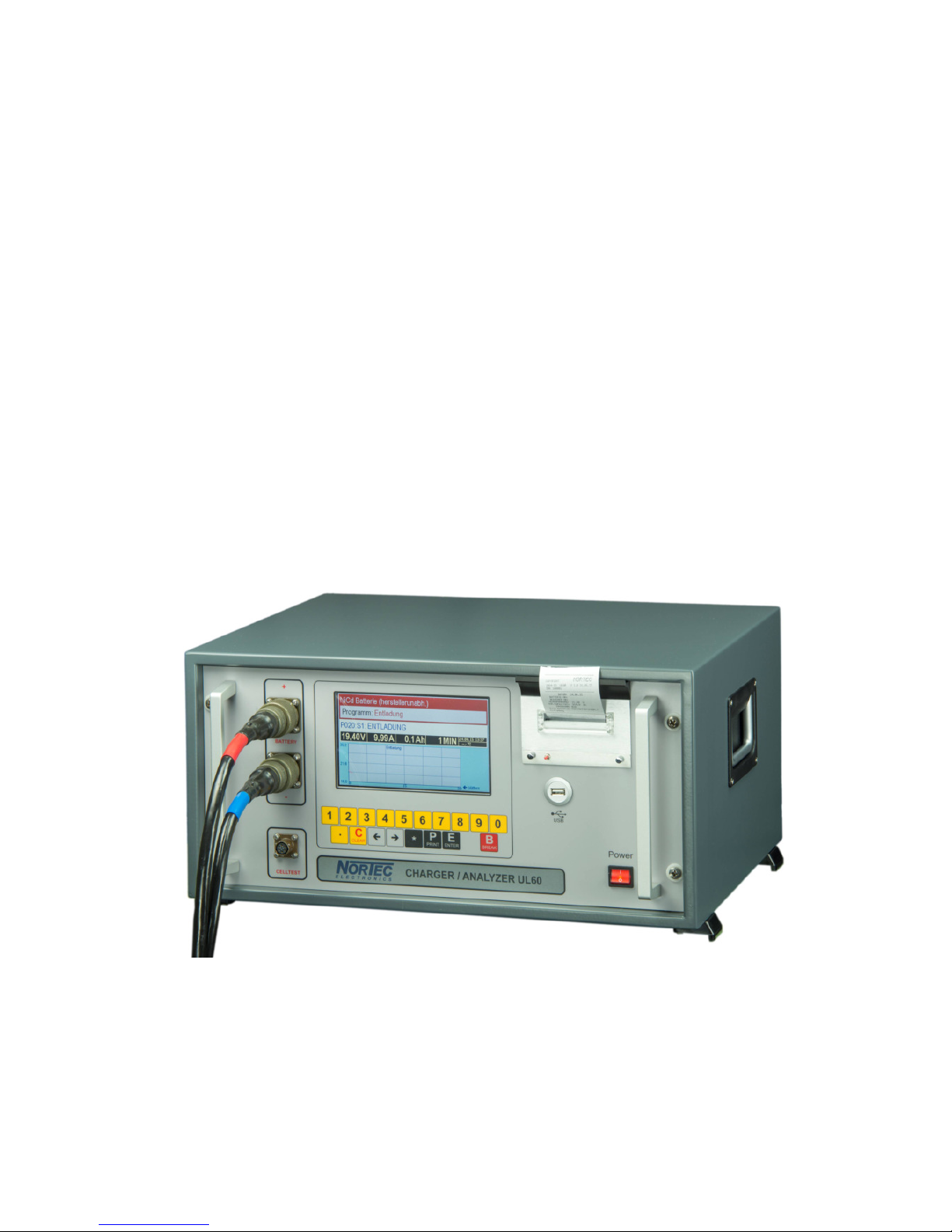
3 Operating and displa elements
The operating and display elements as well as the connector elements of the battery charger
/analyzer UL60 are on the front panel. The connector elements for the automatic cell voltage
measurement and for the interconnectedness with the personal computer are arranged on the rear
panel.
3.1 Front panel
Power ON / OFF-switch with displa
switches the device on or off. ower I – O: switch on I for operation
The lighted switch indicates that mains voltage is available.
Displa
TFT-display (800 × 480 pixel) communicates with the user and shows for example program and
charging parameter.
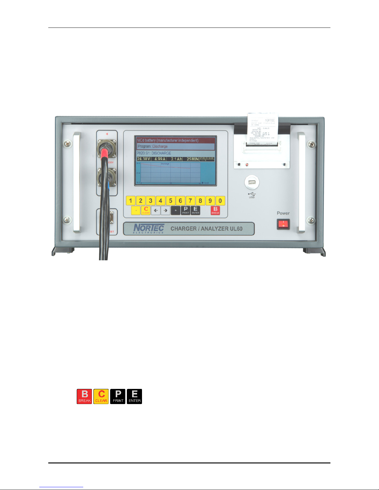
Ke pad
The keys permit interruption, clear faulty inputs, start printing as well as
acknowledge of inquiries or input.
The display allows the user numerical input for example battery parameter or identification number
of the user.
3 Operating and display elements Rear anel
© Nortec Electronics 2018 17
The key opens the menu to choose a different language or the time and starts the programs.
Printer
The inbuilt record printer can be activated before starting, in between or after the battery treatment
by pressing the key all essential battery parameter as well as battery failures will be printed.
Celltester
The UL60 and the manual celltester will be connected via a 6-pole connector of the type VG 95
328 C10-6 N. Cell voltage upto +4.0
V can be measured with the celltester.
Batter connection
The UL60 and the battery is connected via different battery connection cables using two 4-pole
VG-electrical connectors according to VG 95 234.
USB-connection for USB flash drive
The recorded parameter can be stored on USB flash drive.
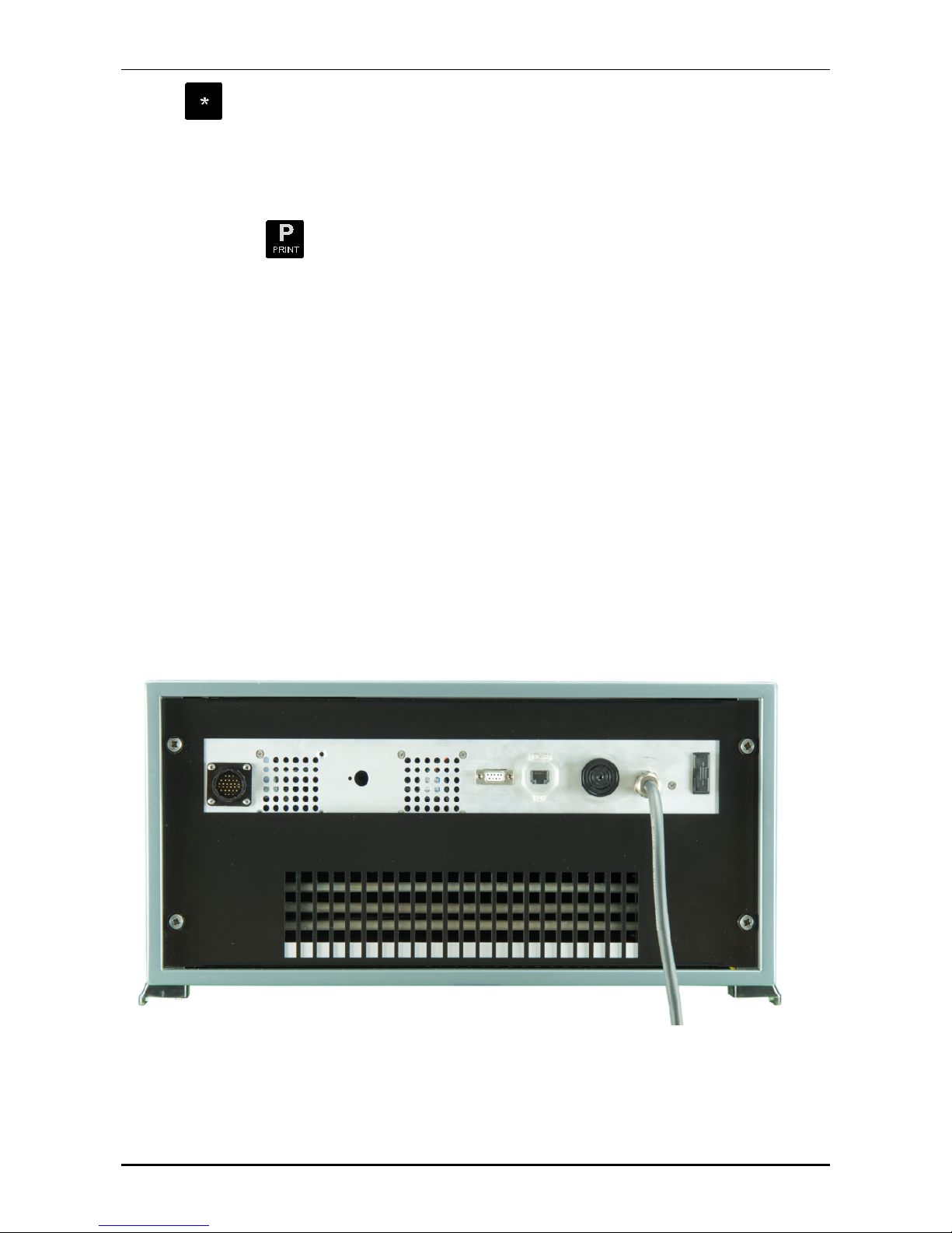
3.2 Rear Panel
Netcable
For voltage supply of the device at 230 VAC-net.
3 Operating and display elements Rear anel
18 © Nortec Electronics 2018
Line Fuse
To secure mains inlet.
Signal generator
The user will be informed about the state of the battery or actions to be taken by the alarm
annunciator in use for battery failures, false inputs or after a treatment is finished and an action is
necessary to continue.
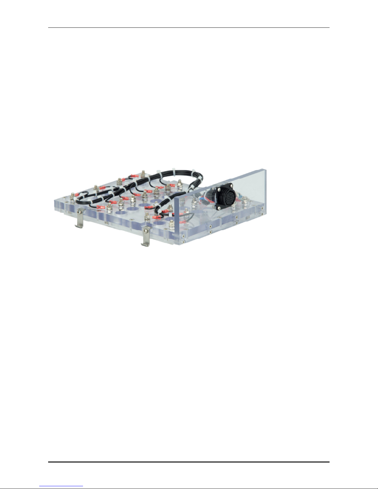
Junction box 28-poles
For the connection of an automatic celltester which can be delivered for different NiCd-batteries.
Fig. Automatic celltester (without temperature sensor)
Sub–D (9-pole) connector plug
for connection to RS 232 interface of personal computer for software update.
Ethernet connection RJ45
for network or browser connection to view data or for being able to print data after the program
finshed.

4 rinciples of operation Connection activities
© Nortec Electronics 2018 19
4 Principles of operation
4.1 Connection activities
The standard procedure for all programs is as follows:
Connect to 230
VAC-net
Connect battery
Net switch OWER I - O use I „In operation“
After this routine, the selftest starts.
NOTE! In case of error message the routine will not continue.
After switching on the already connected battery must be chosen in the menu. ress the keys
as well as . The possible battery types are listed in chapter 8.2 age 30.
4.2 Installation
The device must be set up in a way that additional and used air can pass (minimum 10 cm free
space behind the device).
The cooling air comes from the bottom and gets out at the rear side. Operating in open area for
example in a tent take care that the device does not stand on a dusty ground because dirt can
influence the cooling effect.
The device has to be operated in the supposed housings or racks because the fan in the rack is
unprotected and thus can cause device damage or risk of injury.
4.3 Warning notes
Caution avoid contact!
The rear part of the rack can heat up especially during discharging programs.
Increase in temperature of the heat sink is regulated and will end in a device shut down if too high.
Do not open device during operation!
After disconnecting of the device from the 230VAC net there can be dangerous voltages because
of loaded capacitors. Maintenance of the device should only be done by the manufacturer in order
to secure guarantees!
Attention: The manufacturer does not assume liability for damages caused by the user
incorrect installation, initial operation or use.
If the UL60 is in use for aeronautical engineering the device has to be repaired and cali-
brated b the manufacturer onl .

5 Technical data Electrical input and output parameter
20 © Nortec Electronics 2018
5 Technical data
5.1 Electrical input and output parameter
Input voltage : 230
VAC 10% (single phase)
Feed frequency : 45 to 60
Hz
Input power : 3000
VA
Mains fuse external : 16
A semi time-lag
Fan power : About 100/300
litre/minute
Charging current range : 0.5 – 60
A (to 31
V)
Charging voltage range : 0.5 – 40
A (> 31
V)
Discharging current range : 0.5 – 60
A
Charging voltage range : 0.1 – 40
V (using NiCd reload upto 41.5
V)
Discharging voltage range : 0.1 – 40
V
Voltage precision : < 0.1
% adjusted value plus 5
digits
Current precision : < 3
% adjusted value 5
d
igits
Temperature precision : < 2C
Isolation : VDE 0160, class I
Safety class : I 20
Working temperature : 0 - + 45C
Weight : About 32 kg (in19’’-housing without battery cable)
Dimensions : Width 504
mm, height
242 mm, depth
400 mm
Distance from obstacles for used air : > 100
mm
Interfaces : USB 2.0; RS232, Ethernet RJ45
5.2 Temperature range
The functions of the device are guaranteed in temperature range from 0 C upto +45 C.
The precision of the visual display and the printed record of the charging and discharging parame-
ter correspond to the precision specified in chapter 5.1.
The precision of output data is guaranteed in the temperature range from 0 C to +45 C for 2
years starting from the delivery date of the device.
5.3 Calibration
We recommend a first calibration by the manufacturer Nortec Electronics or by an authorized part-
ner company after 2 years.
After that for safety related engineering a yearly calibration and maintenance is recommend. Addi-
tionally, please pay attention to the internal and external rules laid down by the competent authori-
ties.
Table of contents
Other nor-tec Batteries Charger manuals


