Vanner ITC-Series User manual

Owner’s Manual
ITC-Series Inverter Page 1 Owner’s Manual 8/07/03
ITC-Series
Inverter/Charger System
Model ITC12-2100 and 3200
Vanner Incorporated
4282 Reynolds Drive
Hilliard, Ohio 43026
(614) 771-2718
1-800-ACPOWER
www.vanner.com
Owner’s Manual D911149
August 18,2003
File D911149-A.doc

ITC-Series
ITC-Series Inverter Page 27/18/03
Notes

! "# $ %
! "# $ %
&&
Table of Contents
ITC-Series Inverter Page 3 Owner’s Manual 8/07/03
Table of Contents
1 SYSTEM FEATURES AND SPECIFICATIONS
................................
................................
................................
..
5
1.1 GENERAL DESCRIPTION
................................
................................
................................
................................
......
5
1.2 SYSTEM FEATURES
................................
................................
................................
................................
................
6
1.3 SPECIFICATIONS
................................
................................
................................
................................
...................
7
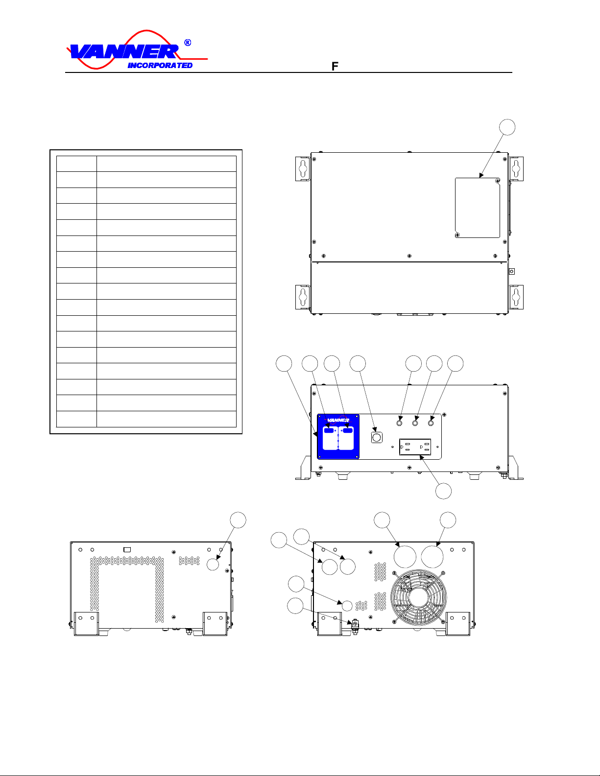
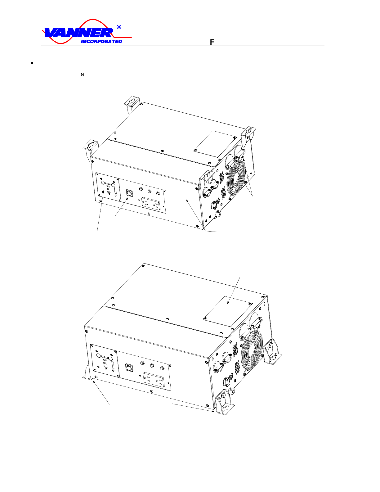
1.4 COMPONENT IDENTIFICATION/LOCATION
................................
................................
................................
........
8
2 DESCRIPTION OF OPERATION
................................
................................
................................
.........................
13
2.1 INVERTER
................................
................................
................................
................................
............................
13
2.2 BATTERY CHARGER
................................
................................
................................
................................
...........
14
2.3 GEN START/AUTO-THROTTLE
................................
................................
................................
..........................
15
2.4 CHARGER AND APM PROGRAMMING
................................
................................
................................
..............
16
3CUSTOMER WIRING IDENTIFICATION
................................
................................
................................
........
17
3.1 AC INPUT & OUTPUT WIRING
................................
................................
................................
.........................
17
3.2 DC (BATTERY) WIRING
................................
................................
................................
................................
....
17
3.3 FRONT PANEL CONTROL/DISPLAY OUTLET
................................
................................
................................
...
17
3.4 SYSTEM ON/OFF SWITCH
................................
................................
................................
................................
18
3.5 REMOTE SIGNAL CONTACTS
................................
................................
................................
.............................
18
4 INSTALLATION
................................
................................
................................
................................
......................
19
4.1 BASIC GUIDELINES
................................
................................
................................
................................
.............
19
4.2 DC WIRING
................................
................................
................................
................................
........................
20
4.3 AC WIRING
................................
................................
................................
................................
........................
21
4.4 SYSTEM START-UP AND TESTING
................................
................................
................................
......................
23
5 GENERAL INFORMATION SECTION
................................
................................
................................
..............
23
5.1 GENERIC INVERTER DESCRIPTION
................................
................................
................................
..................
23
5.2 INVERTER SIZING
................................
................................
................................
................................
...............
24
5.3 DC POWER CONSUMPTION
................................
................................
................................
...............................
25
5.4 BATTERY TERMINOLOGY AND RATINGS
................................
................................
................................
.........
25
5.5 SIZING THE INVERTER BATTERY
................................
................................
................................
......................
27
5.6 BATTERY AND CHARGING SYSTEM CONSIDERATIONS
................................
................................
...................
27
5.7 BATTERY CHARGING GUIDELINES
................................
................................
................................
...................
28
6 MAINTENANCE & TROUBLESHOOTING
................................
................................
................................
......
29
6.1 PREVENTATIVE MAINTENANCE
................................
................................
................................
........................
29

' ()*+,*+-. /0
' ()*+,*+-. /0
11
ITC-Series
ITC-Series Inverter Page 47/18/03
Figures
F 1 Figure 1.1-1 System Diagram
................................
................................
................................
.....................
5
F 2 Figure 1.4-1 Component Location
................................
................................
................................
...............
8
F 3 Figure 1.4-2 ITC Control/Display Unit
................................
................................
................................
..........
9
F 4 Figure 1.4-3 ITC Control/Display Unit Component Identification
................................
................................
9
F 5 Figure 1.4-4 Suspended Mounting Configuration
................................
................................
......................
10
F 6 Figure 1.4-5 Bench Mount Configuration
................................
................................
................................
...
10
F 7 Figure 1.4-6 Suspended Dimensions in Inches
................................
................................
.........................
11
F 8 Figure 1.4-7 Bottom Mount Dimensions in Inches
................................
................................
.....................
11
F 9 Figure 1.4-4 Customer Terminations
................................
................................
................................
.........
12
F 10 Figure 2.2-1 Charging/Voltage Curves
................................
................................
................................
....
14
F 11 Figure 2.4-1 APM/Charger/Config DIP Switch Settings
................................
................................
..........
16
F 12 Figure 3-1 Customer Terminations
................................
................................
................................
..........
17
F 13 Figure 4.1-1 Shelf Mount Configuration
................................
................................
................................
...
19
F 14 Figure 6.1-1 Options Terminal Strip
................................
................................
................................
.........
29
Tables
T 1 Figure 2.2-2 Battery Charger Factory Setpoints
................................
................................
........................
15
T 2 Table 4-1 DC Cable and Fuse Sizing Chart
................................
................................
..............................
20

2 34567 56 89 : ;
2 34567 56 89 : ;
<<
Front Panel Wiring Identification
ITC-Series Inverter Page 5 Owner’s Manual 8/07/03
Introduction
Thank you for purchasing the Vanner ITC-Series inverter/charger system. We are confident that you will be
satisfied with its performance and its many features. With proper installation and care, you can look forward to
years of service from this high performance product.
This document will describe the operation, technical specifications and installation procedures for the ITC-Series
inverter/charger system. If you require additional information please contact your dealer, or contact Vanner
directly at the location shown on the cover of this manual.
1System Features and Specifications
1.1 General Description
The ITC-Series system consists of a DC to AC true sine wave inverter, a 12-volt battery charger, an automatic
AC transfer switch, and a microprocessor based controller. An important feature of this system is the ITC-Series
Control/Display Unit user interface.
Control/Relay
Board
Power
Stage
Transformer
ITC-Series Inverter System
AC Out 120 Vrms
Relay Contol Output for AutoThrottle
120 Vrms Input for Charger
Control Display Panel
+12 VDC
Low Battery Indicator Contact
Overload
Overload
Low
Battery
Bulk
Fault
Fault
I N C O R P O R A T E D
Inverter
On/Off
Charger
On/Off
Fuse
12 Volt
Battery
CB In
CB Out
Dead
Battery
Supply
Sig
nal
Rel
ay
s
Microprocessor
Control System
for Inverter/
Charger
On/Off Switch
Optional Remote Switch
GFCI
F 1Figure 1.1-1 System Diagram

= >?@AB @A CD E F
= >?@AB @A CD E F
GG
Front Panel Wiring Identification
ITC-Series Inverter Page 67/18/03
1.2 System Features
H
Inverter
The inverter consists of a sine wave inverter that supplies power when AC loads are applied. Depended on
your model, the inverter develops 2100 or 3200 watts of continuous power. Using TruSine®technology, a
very high quality sine wave is produced. Total harmonic distortion (THD) is less than 4.0 percent. The
inverter also has a three second surge rating of 6400 Watts.
H
Battery Charger with Automatic Power Management
A high efficiency, multi-stage battery charger, allows fully automatic charging of flooded and gel lead acid
battery banks. The efficient 0.85PF, compared to typical 0.59PF on triac type chargers, allows full charger
output from a 30-amp AC source. The system’s Bulk, Absorption, and Float charge cycle quickly charges
and maintains the battery bank. An Equalization charge cycle is provided for flooded lead acid battery
maintenance.
Automatic Power Management (APM) monitors the AC Input current and will reduce the battery charger
output as needed to keep the AC input current below the preset APM Limit.
I
GenStart/Auto-Throttle
The GenStart/Auto-Throttle feature provides a start/stop signal to control an automatic throttle module. The
start/stop signal consists of a contact closure to start the Auto-Throttle based on battery voltage of 12.3 VDC.
The GenStart/Auto-Throttle turns off when the battery charging current falling below 10 amps. Call Vanner
at 1-800-ACPOWER for technical assistance in selecting the proper auto-throttle kit to use for this
application.
I
Low Battery Contact
This contact allows remote monitoring of the Inverters battery status. The contact will closes when battery
voltage falls below 11 volts. This will alert the user to take appropriate measures to avoid shutdown of the
Inverter at 10.5VDC.
I
Remote Power Switch
This loop between Options Terminal 7 and 8 (left side of Options Terminal) allow remote control of the
system On/Off. Tying these two terminals together or optionally, tying the terminal 7 (Remote Switch) to
battery ground applies power to the unit.
Note: The Front Panel switch will always overrule the remote switch in terms of disabling the unit.
J
System Control
The ITC contains a System ON/OFF Switch located in the front of the ITC. This switch is used to turn the
control power ON and OFF. This power switch also has a break out loop for a series switch that can be
placed in a remote location from the unit (See Remote Power Switch above). A control microprocessor
provides a variety of protection interlocks, system fault detection/reporting/recovery, storage of system data
parameters, and high-speed data communications to the ITC Control/Display Unit. This Control/Display Unit
also has individual on/off switches for independent Inverter and Charger control. The ITC will protect itself in
the event of any overload, over temperature, high or low battery voltage condition.
J
ITC Control/Display Unit
The ITC Control/Display Unit is a user interface that is connected to the ITC Control Board via a 6-wire
communication bus. This Control/Display unit can be an integral part of the Inverter or can be removed and
mounted in a remote area to allowing remote system operation. Two of these units can talk to the System
Control Board one Unit would be configured as a Master, and the other as Slave. The configuration switches
on top of the Master allow programming of the Charger current, Automatic Power Management and battery
type settings.
NOTE: It should be noted that if the Control Display unit is taken out of the front of the unit, the cover plate

K LMNOP NO QR S T
K LMNOP NO QR S T
UU
Front Panel Wiring Identification
ITC-Series Inverter Page 7 Owner’s Manual 8/07/03
must be installed in it’s place to insure that debris does not enter the unit through the opening and to
maintain proper airflow through the unit.
1.3 Specifications
Model ITC12-2100 Model ITC12-3200
AC OUTPUT
Voltage (RMS) 120 VAC
Frequency 60 Hz ± 0.5%
AC Waveform Sine Wave
Total Harmonic Distortion (THD) Less than 4.0% @ full power
Power Factor Allowed -1 to 1
Continuous Output Rating @ 25ºC
Phase to Neutral 2100 watts (17.5 amps) 3200 watts (26.7 amps)
Surge Capacity @ 25ºC (3 sec.) 6400 watts
DC INPUT:
Operating Range (12 Volt Nominal) 10.5 to 17 Volts
No Load, Inverter ON 4 amps
No Load, Inverter OFF 0.30 amps
Full power 208 amps 350 amps
INVERTER EFFICIENCY @ 12VDC
200 watts 77%
500 watts 88%
700 watts 88%
1000 watts 88%
1500 watts 86%
2000 watts 84%
2500 watts NA 81%
3000 watts NA 78%
3200 watts NA 77%
AC INPUT
Voltage 120 Volts nominal
Frequency 60 Hz ± 12.5% (52.5 to 67.5)
AC TRANSFER SWITCH
Power Rating 30 amps @ 120 VAC
Transfer Time Less than 40 milliseconds
BATTERY CHARGER
Charger Output Current maximum 80 amps
AC Input Current maximum 30 amps (0.88PF @ rated output)
SYSTEM
Ambient Operating Temperature -40 to+40
V
C (-40 to+104
V
F)
Cooling Exhaust Fan Thermostatically controlled
Mounting Shelf or suspended
Dimensions (Bottom mount position) 8 1/4”H x 18 7/16”W x 13 5/8”D
Weight 66 pounds

W XYZ[\ Z[ ]^ _ `
W XYZ[\ Z[ ]^ _ `
aa
Front Panel Wiring Identification
ITC-Series Inverter Page 87/18/03
1.4 Component Identification/Location
The Figures below show the location of the various components of the ITC system.
INCORPORATED
Inverter
On/Off
Charger
On/Off
Overload
Low
Battery
Fault
Overload
Bulk
Fault
1
TOP VIEW
3
6
7
8
9
4
5
FRONT VIEW
13
2
14
15
16
10
LEFT SIDE VIEW
RIGHT SIDE VIEW
11
12
15
16
OPTIONS CABLE ENTRY
CHASSIS GROUND
ITEM #
1
2
3
4
5
6
7
8
9
10
11
12
13
14
DESCRIPTION
BATTERY TERMINAL ACCESS
REMOTE CABLE INPUT
CONTROL/DISPLAY PANEL
INVERTER ON/OFF SWITCH
CHARGER ON/OFF SWITCH
SYSTEM ON/OFF SWITCH
AC INPUT BREAKER (CB-1)
AC OUTPUT BREAKER (CB-2)
GFCI BREAKER (CB-3)
AC INPUT CABLE ENTRY
BATTERY +
BATTERY -
GFCI OUTLET
AC OUTPUT CABLE ENTRY
OPTIONS CABLE ENTRY
CHASSIS GROUND
F2Figure 1.4-1 Component Location

b cdefg ef hi j k
b cdefg ef hi j k
ll
Front Panel Wiring Identification
ITC-Series Inverter Page 9 Owner’s Manual 8/07/03
Equalize button access
Through Access hole.
Overload
Overload
Low Battery
Bulk
Fault
Fault
INCORPORATED
Inverter
On/Off
Charger
On/Off
On/Off Switch for Inverter
On/Off Switch for Charger
Serial Communications
Connection
Configuration Switches
for Programming
Configuration Switches Access
Configuration Switches
Note: Power Must be
Cycled to read a new
DIP Switch value
F 3Figure 1.4-2 ITC Control/Display Unit
F 4Figure 1.4-3 ITC Control/Display Unit Component Identification
ITEM DESCRIPTION
1 Inverter Indicator
Light Solid when on, flashes when enabled but not on
2 Inverter On/Off
Button Enables/Disables Inverter Function
3 Charger Indicator
Light Solid when on, flashes when enabled but not on
4 Charger On/Off
Button Enables/Disables Charger Function
5 Overload Light Dual Purpose – Indicates if Inverter or Charger is Overloaded
6Low Battery/Bulk
Light Dual Purpose – Indicates Low Battery in Inverter Mode – In charger mode, if on indicates that
Charger is in Bulk Mode and if in Equalize, this light flashes.
7 Fault Light Dual Purpose – Indicates that a fault has occurred in the inverter or Charger – Could be a Over
Temperature shutdown, Low/High Battery Shutdown, Power Stage Fault, or Input AC fault
8 Equalize Button This is used to enable the equalization cycle on the battery during charging.
Overload
Overload
Low Battery
Bulk
Fault
Fault
INCORPORATED
Inverter
On/Off
Charger
On/Off
1
2
3
4
5
6
7
8

m nopqr pq st u v
m nopqr pq st u v
ww
Front Panel Wiring Identification
ITC-Series Inverter Page 10 7/18/03
x
Versatile Mounting System
The mechanical system used for mounting the ITC-Series allows both shelf and under-counter mounting,
while still allowing access to user AC and control terminals through a removable front cover.
ACCESS PANEL REMOVABLE FROM
FRONT WHEN UNDER TABLE
MOUNTED.
DOCKED DISPLAY/CONTROL PANEL
`
DC TERMINATIONS
POWER ON/OFF SWITCH
With Indicator
F 5Figure 1.4-4 Suspended Mounting Configuration
Mounting Feet shown in Benchtop
Mounting Configuration
Access Cover To DC
Terminations
F 6Figure 1.4-5 Bench Mount Configuration

y z{|}~ |}
y z{|}~ |}
Front Panel Wiring Identification
ITC-Series Inverter Page 11 Owner’s Manual 8/07/03
18
10 7/8
19 1/4
13 5/8
16 3/4
8 1/8
7 5/16
8 3/4
ITC DIMENSIONS FOR SUSPENDED MOUNTING
F 7Figure 1.4-6 Suspended Dimensions in Inches
19 1/4
18
10 7/8
16 3/4
13 5/8
7 5/16
8
ITC DIMENSIONS FOR SHELF MOUNTING
F 8Figure 1.4-7 Bottom Mount Dimensions in Inches

Front Panel Wiring Identification
ITC-Series Inverter Page 12 7/18/03
GND
OPTIONS TERMINAL
STRIP
P14
HOT
NEU
GND
AC INPUT
P15
HOT
NEU
GND
AC OUTPUT
P6
P5
REMOTE MASTER AND
SLAVE CONNECTORS
REMOTE
SWITCH
REMOTE LED
COM
N/O
N/O
LOW BATT
COM
AUTO-
THROTTLE/
GENSTART
P3
F 9Figure 1.4-4 Customer Terminations

Front Panel Wiring Identification
ITC-Series Inverter Page 13 Owner’s Manual 8/07/03
2DESCRIPTION OF OPERATION
2.1 Inverter
The System ON/OFF Switch, located on the front panel, allows the user to turn the system power ON and OFF
and to reset the system after a fault.
The Charger ON/OFF and Inverter ON/OFF switches, located on the Control/Display Unit enable or disable the
Charger or Inverter Functions. The corresponding light next to Inverter/Charger switches will be steadily on when
the unit is in the Inverter or Charger mode. These Inverter and Charger lights will blink if the mode is not currently
on, but are enabled (Example: The Inverter light will blink when the Inverter is Enabled, the ITC is plugged into
the utility, and the Charger is Active).
The Inverter AC Output Circuit Breaker is a 1 pole, 30 amp breaker marked “CB-2” on the front unit. The CB-2
breaker protects the Inverter AC output and a second Breaker (CB-1) protects the Battery Charger AC input
against a severe overload. This CB-1 breaker also protects AC Pass through Power. If this CB-1 breaker trips
during charger operation, it must be reset.
Inverter Protective Interlocks
The Inverter operation is protected by a series of safety interlocks that protect against most failures such as
overloads, over-temperature conditions or other conditions where the unit may be asked to operate outside safe
battery voltages. These faults will trigger a display of the “Fault” and or “Overload” Lights on the Control/Display
panel and are listed below:
Low Battery The inverter continually monitors battery voltage. If battery voltage falls below the Low
Battery Shutdown 10.5 VDC setpoint the inverter will shut OFF. Auto-restart will restart the
inverter after battery voltage rises above the Low Battery Warning 11 VDC setpoint (after 5
minutes).
High Battery The inverter will shut OFF if battery voltage rises above the High Battery 17 VDC setpoint.
Over Temperature The inverter will shut OFF if internal temperature sensors detect a high temperature
condition that would damage the inverter.
Over Load If a short circuit or an overload is applied to the inverter’s output the inverter will shut down.
Battery High The unit has shut down due to the Battery voltage is above High Battery Shutdown setpoint
of 17 VDC.
Battery Low Battery voltage is below Low Battery Warning setpoint and soon may reach Low Battery
Shutdown setpoint of 10.5 VDC.
Current Limit Inverter AC output current is at the Maximum Current allowed and is presently in “Surge”.
The AC voltage will decrease if load increases. Overload Shutdown will occur if voltage goes
below 105VAC for 3 second.
Overload Inverter has shut down due to overload. High AC load caused inverter output voltage to fall
below tolerance for three seconds.
Hardware Fault Internal circuits failure or power brick high temperature will shut down system.
Overheat The SCR plate or power brick overheating will cause the system to shutdown.
If the unit has faulted there are the two following options:
1. Auto-restart After shutting down for any of the above fault conditions, the inverter will try to restart itself
every 5 minutes if Auto-Restart is Enabled and the fault condition no longer exists.
2. Manual restart You can manually restart the system after the fault conditions are removed. Reset the
inverter by turning the System ON/OFF Switch OFF and then ON.

¡ ¢ £
¡ ¢ £
¤¤
Front Panel Wiring Identification
ITC-Series Inverter Page 14 7/18/03
2.2 Battery Charger
The battery charger’s advanced design incorporates an automatic, multi-stage charger. This design enables the
unit to automatically charge batteries, which maintains the battery’s integrity and reduces the likelihood of
premature battery failure. The battery charger is designed to be used with lead-acid type batteries including
sealed and gel types, but not for nickel-cadmium (Ni-Cad) or nickel-iron types.
Battery Charging Sequence
Stage 1:
Bulk Charge Stage
The charger always starts in the Bulk charge stage each time shore power becomes present and/or each time
the charger is turned ON. In the Bulk charge stage, the system charges at the ‘Bulk Charge Amps’ setpoint until
the battery voltage rises to the ‘Bulk Charge Voltage’ setpoint. Then the voltage is held at that setpoint until
charging current has fallen to 5 amps above the ‘Battery Absorption Amps’ setpoint (Absorption Amps = 50% of
Bulk Amps). This ends the Bulk Charge Stage and begins the Absorption Charge Stage. The charger will not
enter the Bulk Stage again until shore power is re-applied, or until the charger or the system is turned ON again.
VOLTAGE
CURRENT
TIME
BULK
ABSORPTION
(OPTIONAL)
EQUALIZE
FLOAT
TRIGGER POINT
F 10 Figure 2.2-1 Charging/Voltage Curves
Stage 2:
Absorption Charge Stage
The Absorption Charge Stage provides a controlled “overcharging” of the battery that is necessary to bring the
battery up to full charge. The battery is charged at the ‘Absorption Charge Amps’ (Absorption Amps = 50% of
Bulk Amps) until one of following three conditions occur that signals the end of the Absorption Stage;
Time: The Absorption Maximum Time setpoint is reached
Time: The Absorption Charge Stage time has reached ½ of the duration of the Bulk Charge Stage.
Voltage: Battery voltage reaches the ‘Absorption Voltage’ setpoint
Stage 2A
Equalize Charge Cycle
When Equalize Mode is ENABLED (by inserting a paperclip or similar device through the Control/Display unit
Equalize hole), one Equalize Charge Cycle will follow the Absorption Charge Stage. The Equalize Cycle will last
for the ‘Equalize Time’ setpoint of 15 minutes. Equalize Mode will automatically switch to DISABLED at the end
of the Equalize Charge Cycle. During the Equalize Cycle the battery is charged at the ‘Absorption Charge Amps’
setpoint and the Equalize Voltage 15.5 VDC setpoint.
The Equalize Charge Cycle provides a deliberate overcharging of the battery to remove sulfate, which
accumulates on the battery plates through normal use. Equalizing returns battery cells to equal performance

¥ ¦§¨©ª ¨© «¬ ®
¥ ¦§¨©ª ¨© «¬ ®
¯¯
Front Panel Wiring Identification
ITC-Series Inverter Page 15 Owner’s Manual 8/07/03
levels, which improves battery performance and extends battery life. Consult the battery manufacturer for their
recommendation regarding how often the Equalize Cycle should be performed.
CAUTION
Do not equalize sealed (valve regulated lead acid, AGM or gel) batteries! Consult battery manufacturer for
equalizing guidelines. Do not equalize more often than approximately once a month. Check battery fluids after
equalizing is complete, as gassing will occur. Use Equalize Mode only if batteries are in a well ventilated area!
Stage 3:
Float Charge Stage - Maintenance Mode
In the Float Stage the charging voltage is reduced to the ‘Float Charge Voltage’ setpoint and charging current is
limited to the ‘Absorption Charge Amps’ setpoint. The charger will remain in the Float Stage until shore power is
reapplied, or until the charger or system is turned OFF and then ON again.
Charging Setpoints
The ITC’s battery charger factory setpoints are for wet batteries. Do not use GEL type batteries without changing
the factory setpoints via the configuration switches.
CAUTION
Do not operate DC loads, such as DC lights, pumps, etc., during battery charging. The loads may cause
overcharging by preventing the charging stages from reaching their ‘trigger points’ or may cause the battery to
run down even though the charger is ON.
T 1Figure 2.2-2 Battery Charger Factory Setpoints
Guideline Factory Setpoint
(for Wet Battery)
Factory setpoint for
Gel/AGM Battery
Bulk Charge Volts 14.2 VDC 14.1 VDC
Bulk Charge Current 20% C Rate 80 Amps 80 Amps
Absorption Charge Volts 14.5 VDC 14.2 VDC
Absorption Charge Current 40 Amps 40 Amps
Absorption Maximum Time 10 Minutes 10 minutes
Float Charge Volts 13.2 VDC 13.7 VDC
Equalize Volts Wet only 15.5 VDC Not used
Equalize Maximum Time Wet only 15 Minutes Not used
Battery ‘C Rate’ is equal to battery Amp Hour capacity.
Automatic Power Management (APM)
A key feature of the battery charger operation is Automatic Power Management (APM). This feature monitors the
AC input current and will reduce the battery charger output as necessary to keep the AC input current under the
APM setpoint. The APM circuit will not limit power to the passthrough AC loads. If the passthrough AC loads
exceed 30 Amp, the battery charger output will be reduced to zero and the breaker may trip.
2.3 Gen Start/Auto-throttle
It should be noted that the Generator Start Operation is designed to minimize the generator run time, so at the
present set points there is no Absorption stage per se. Therefore, the batteries must be periodically conditioned
by leaving the generator on, or charging them with another system.
The Gen Start/Auto-throttle feature is designed for use in installations where a generator is used to provide AC
input power for battery charging. Alternately, these contacts are used to enable an Auto-throttle when the battery
voltage drops below the 11.0 VDC setpoint. The Gen Start/Auto-throttle feature provides a contact closure to
signal the generator to start when battery voltage falls below the ‘Gen Start Volts’ 11.0 VDC setpoint. The Gen
Start/Auto-throttle contacts open when bulk charging current fall below the ‘Gen Stop Amps’ 10 Amp DC
setpoint. The Bulk charging current is checked every 4 minutes, therefore the minimum generator ON time is 4
minutes. The contacts are NEC Class 2, rated 2 amps at 12 VDC.
It should be noted that the Gen Start/Auto-throttle contacts are shown in Figure 1.4-4 Customer Terminations,

° ±²³´µ ³´ ¶· ¸ ¹
° ±²³´µ ³´ ¶· ¸ ¹
ºº
Front Panel Wiring Identification
ITC-Series Inverter Page 16 7/18/03
and likewise a similar set of Normally Open Contacts are available to indicate a “Low Battery” condition.
Caution
The battery charging process will be affected if 12VDC loads are being powered during battery
charging. The increased charger output, required to power those loads, may keep the charger from reaching
the ‘Gen Stop Amps’ setpoint.
2.4 Charger and APM Programming
The chart below shows the control switch settings for programming the ITC Charger and APM settings.
NOTE: It should be noted that the power switch on the front of the unit must be cycled to read in the new
Control Switch settings into memory. The new values will not be recognized until this takes place.
The first 4 (1-4) switches program in the Maximum Charger Current and the next 4 (5-8) program in the APM
Current Limit.
The next switch (switch 9) is for selecting either Wet or Gel type batteries.
The next switch (switch 10) is reserved for future expansion.
The next switch (switch 11) is reserved for future expansion.
The next switch (switch 12) is reserved for selecting a Master/Slave remote with multiple Control/Display Units.
Note: The figure below is also available on the Rear of the Control/Display Unit.
| - ON
O - OFF
0
2
4
6
8
10
12
14
16
18
20
22
24
26
28
30
5
|
|
|
|
|
|
|
|
O
O
O
O
O
O
O
O
6
|
|
|
|
O
O
O
O
|
|
|
|
O
O
O
O
7
|
|
O
O
|
|
O
O
|
|
O
O
|
|
O
O
8
|
O
|
O
|
O
|
O
|
O
|
O
|
O
|
O
DIP SWITCH
POSITION
APM
CURRENT
(AMPS)
5
10
16
21
26
32
37
42
48
53
58
64
69
75
80
1
|
|
|
|
|
|
|
O
O
O
O
O
O
O
O
2
|
|
|
O
O
O
O
|
|
|
|
O
O
O
O
3
|
O
O
|
|
O
O
|
|
O
O
|
|
O
O
4
O
|
O
|
O
|
O
|
O
|
O
|
O
|
O
DIP SWITCH
POSITION
CHARGER
CURRENT
(AMPS)
BATTERY TYPE
SPARE
WET
GEL
OFF
ON
SPARE
CHARGER
OUTPUT
CURRENT
SELECTION
MASTER/SLAVE
APM
CURRENT
SELECTION
1
2
3
4
5
6
7
8
9
10
11
12
DIP SWITCH
FUNCTION
SW POSITION
OFF
ON
OFF
ON
OFF
ON
SLAVE
MASTER
Note:
After a new
switch setting is set,
the power switch
must be cycled on the
main unit for the new
setting to take effect.
F 11 Figure 2.4-1 APM/Charger/Config DIP Switch Settings
The graphic to the left indicates the factory defaults.
Switches 1 through 4 show an 80-amp charger. Switches
5 through 8 indicate 30-amp automatic power
management. Switch 9 has selected Wet Cell battery
configuration. Switch number 12 indicates “Master”
display/control unit.
1
2
3
4
5
6
7
8
9
10
11
12
1
0

» ¼½¾¿À ¾¿ Á à Ä
» ¼½¾¿À ¾¿ Á à Ä
ÅÅ
Front Panel Wiring Identification
ITC-Series Inverter Page 17 Owner’s Manual 8/07/03
3Customer Wiring Identification
GND
OPTIONS TERMINAL
STRIP
P14
HOT
NEU
GND
AC INPUT
P15
HOT
NEU
GND
AC OUTPUT
P6
P5
REMOTE MASTER AND
SLAVE CONNECTORS
REMOTE
SWITCHGND
REMOTE LED
COM
N/O
N/O
LOWBATT
COM
AUTO-
THROTTLE/
GENSTART
P3
F 12 Figure 3-1 Customer Terminations
All field wiring enters the ITC housing through the side panels.
3.1 AC Input & Output Wiring
The AC wiring compartment is located on the front right side of the unit. A removable access cover covers this
compartment. Two cable clamps are installed for the AC input and AC output wiring. The removable access
cover can be removed by simply removing the screws on the front panel of the unit (ONLY!). There is no need
to remove screws from the top or sides of the unit to gain access to the AC wiring compartment. Inside the
compartment is a terminal strip for making AC input and AC output connections (P14 and P15).
NOTE
The AC output voltage and the required AC input voltage of the ITC is 120 VAC, 60Hz.
3.2 DC (Battery) Wiring
A DC wiring compartment is located behind the wiring panel on the right side of the unit. The compartment
contains a removable access cover on the top of the inverter and two cable clamps for the battery positive and
battery negative cables. The inverter’s battery cable terminal studs are 5/16-18 and can accommodate Cable
sizes up to 250 MCM.
3.3 Front Panel Control/Display Outlet
This is a RJ-11 (6-Wire) jack (P5) for communications with the Control/Display Unit. A secondary
Control/Display unit can be plugged into the P6 jack who would be configured as a slave.

Æ ÇÈÉÊË ÉÊ ÌÍ Î Ï
Æ ÇÈÉÊË ÉÊ ÌÍ Î Ï
ÐÐ
Front Panel Wiring Identification
ITC-Series Inverter Page 18 7/18/03
3.4 System ON/OFF Switch
Use this rocker switch to turn the system ON and OFF and to reset the system. This switch is located on the front
panel of the system. If placed in the “OFF” position, this switch will override the operation of a remote ON/OFF
switch connected to terminals 7 and 8 of the Options connector shown in Figure 3-1 – Customer Terminations.
WARNING: The System ON/OFF Switch does not interrupt the DC input power to the system, so it must be
noted that dangerous DC voltages still exist inside the unit, even if the power switch is turned off.
3.5 Remote Signal Contacts
Terminal Contacts provide capabilities for Remote Inverter Power ON/OFF and Power indication, Remote Low
Battery Warning indication, and Gen Start/Auto-Throttle control. Contacts are rated 2 amps at 12 volts, Class 2
circuits. Wiring connections are made through an 8 position Options terminal block. Screw pressure-clamp
terminals accept up to 14-gauge wire.
A remote power switch will control the system by tying terminals 7 and 8 of the options connector (shown in
Figure 3-1) together. This will actuate an internal relay that turns the control power on. The Power On/Off switch
on the front panel defeats this remote switch.
In addition, a terminal for a remote LED indicator is provided (terminal 6) with a current limiting resistor integral to
the circuit.

Ñ ÒÓÔÕÖ ÔÕ ×Ø Ù Ú
Ñ ÒÓÔÕÖ ÔÕ ×Ø Ù Ú
ÛÛ
Installation
ITC-Series Inverter Page 19 Owner’s Manual 8/07/03
4INSTALLATION
Unpacking the Inverter
Inspect the shipping container and equipment for loose or damaged parts. If any damage is found, immediately
notify the freight carrier.
4.1 Basic Guidelines
The wiring of your inverter installation should conform to the National Electric Code (NEC) and any other state or
local codes in effect at the time of installation. These codes have been written for your protection and their
requirements should be followed.
Mounting
Locate a secure, dry, flat horizontal surface large enough to mount the inverter. The location should be as close
to the battery as possible without being in the same compartment and should provide adequate ventilation to
maintain room temperature while the inverter is operating. The location must allow unobstructed cooling airflow
at sides, rear, and bottom of the unit, and the location must be free from road spray, dripping water or other
moisture contamination. A recommended minimum clearance of 4 inches (102 mm) should be maintained on all
sides of the unit.
WARNING: Risk of fire or explosion. The inverter must not be mounted in fuel storage areas, battery
compartments, or other hazardous areas where potentially explosive gases may be present.
WARNING: It is important to utilize the included mounting brackets mounting. Mount the inverter in the
under cabinet method or bolted to a shelf.There must be a minimum of 5/8 inches below the unit, which
provides adequate airflow to cool the Inverter/Charger. If the unit is to be set on its base (in a shelf mount
configuration) and not bolted down, make certain that the mounting feet are bolted to the unit to provide the
adequate clearance as shown below.
INCORPORATED
Inverter
On/Off
Charger
On/Off
Overload
Low
Battery
Fault
Overload
Bulk
Fault
F 13 Figure 4.1-1 Shelf Mount Configuration
NOTE
The wiring of your inverter installation should conform to the National Electric Code (NEC) and any other state or
local codes in effect at the time of installation. Article 551 of the NEC requires any DC cable from a battery,
which measures longer than 18 inches along its length, be protected by a fuse. Other codes may require each
ungrounded output conductor from a storage battery, other than to the engine cranking motor, to have a
manually reset trip-free circuit breaker or fuse within 18 inches of the battery as measured along the conductor.

Ü ÝÞßàá ßà âã ä å
Ü ÝÞßàá ßà âã ä å
ææ
Installation
ITC-Series Inverter Page 20 7/18/03
4.2 DC Wiring
Preliminary Considerations
1. BE AWARE that, as a large number of capacitors become charged upon completion of the DC circuit,
THERE WILL BE A LARGE SPARK when the last battery connection is made. The spark is normal and will
occur every time the batteries are connected.
2. The DC cables should be as short as possible. It is electrically more efficient to run the lower current AC
wiring longer distances than the DC cables. (See DC Cable Sizing Chart for proper size.)
3. Route the DC positive and negative cables as close together as possible, and use cable ties to keep them
together. This reduces some electromagnetic radiation that could interfere with some sensitive electronics.
3. On vehicle installations do not use the vehicle chassis as the DC negative conductor. Use a cable the same
size as the DC positive to go directly from the inverter to the battery negative.
4. Route the AC and DC power wiring separately, and with as much physical separation as possible, from low
voltage wiring such as audio and video signal wires.
5. DC power input cables that pass through steel or other ferrous metal walls need to pass through the same
hole. If two holes are required, cut a slot connecting the two holes to prevent a transformer effect.
6. Do not allow wire fragments or metal shavings to fall into the DC wiring compartment or to enter the inverter
in any way. Severe inverter damage will result which is not covered by the warranty.
7. Do not connect the inverter to the battery at this time. Final battery connections will be made after all
installation issues have been inspected.
8. WARNING: A poorly made high current connection may result in the risk of fire and personal injury.
9. WARNING: Be sure of the polarity of the DC input wiring. Reverse polarity may severely damage your
inverter and is not covered under warranty. Risk of fire or explosion of batteries may occur due to very high
currents.
10.A DC fuse is required to properly protect the inverter.
11.The table below shows the recommended minimum cable size which should be used. Wire sizing charts
published in the NEC may allow a greater amp capacity than we recommend. We have sized the cable for a
minimum voltage drop on the cable to maintain better performance of your inverter installation. The inverter’s
DC cable terminal lugs can accommodate cable sizes up to 250 MCM.
T 2Table 4-1 DC Cable and Fuse Sizing Chart
DC Cable Size Max. Distance
from Inverter to
Battery in Feet
2100W (3200W)
Terminal Lug -
Amp Part
Number
Terminal Crimping Tool – Amp Part
Number
250MCM Copper
Conductor 24 (16) 325703 AMP DYNA-CRIMP Head - Part #69099
AMP DYNA-CRIMP Die - Part #46751-2
AMP DYNA-CRIMP Hydraulic Power Units -
Part #69120-1 or 314979-1
4/0 Copper
Conductor 20 (13) 321271 AMP Rota-Crimp Part# 600850 (2/0-4/0)
Fuse
Information
Bussman Part
Number
Vanner Part
Number
2100W
3200W
Bussman ANL300
Bussman ANL500
03645
03646
Fuse Holder Bussman 4164 03637
This manual suits for next models
2
Table of contents
Other Vanner Batteries Charger manuals

Vanner
Vanner SPC0182 User manual

Vanner
Vanner VSC12 User manual

Vanner
Vanner Silent Runner SRC12-1100PT User manual

Vanner
Vanner SP00175 User manual

Vanner
Vanner SP00143/181 User manual

Vanner
Vanner ITC24-360 User manual

Vanner
Vanner SP00155 User manual

Vanner
Vanner TruSine TSC24-4500 User manual

Vanner
Vanner SP00155 User manual
Popular Batteries Charger manuals by other brands

Victron energy
Victron energy Blue Smart IP67 Charger 12/7 manual

Railroad Products
Railroad Products RRP-433 instruction manual

Analytic Systems
Analytic Systems BCA150 Installation & operation manual

Eaton
Eaton 81215-SBP quick guide

Ergotron
Ergotron Yes 20 owner's manual

CTEK
CTEK MULTI US 7000 user manual