sedia systems FT20 User manual

Assembly Instructions FT20
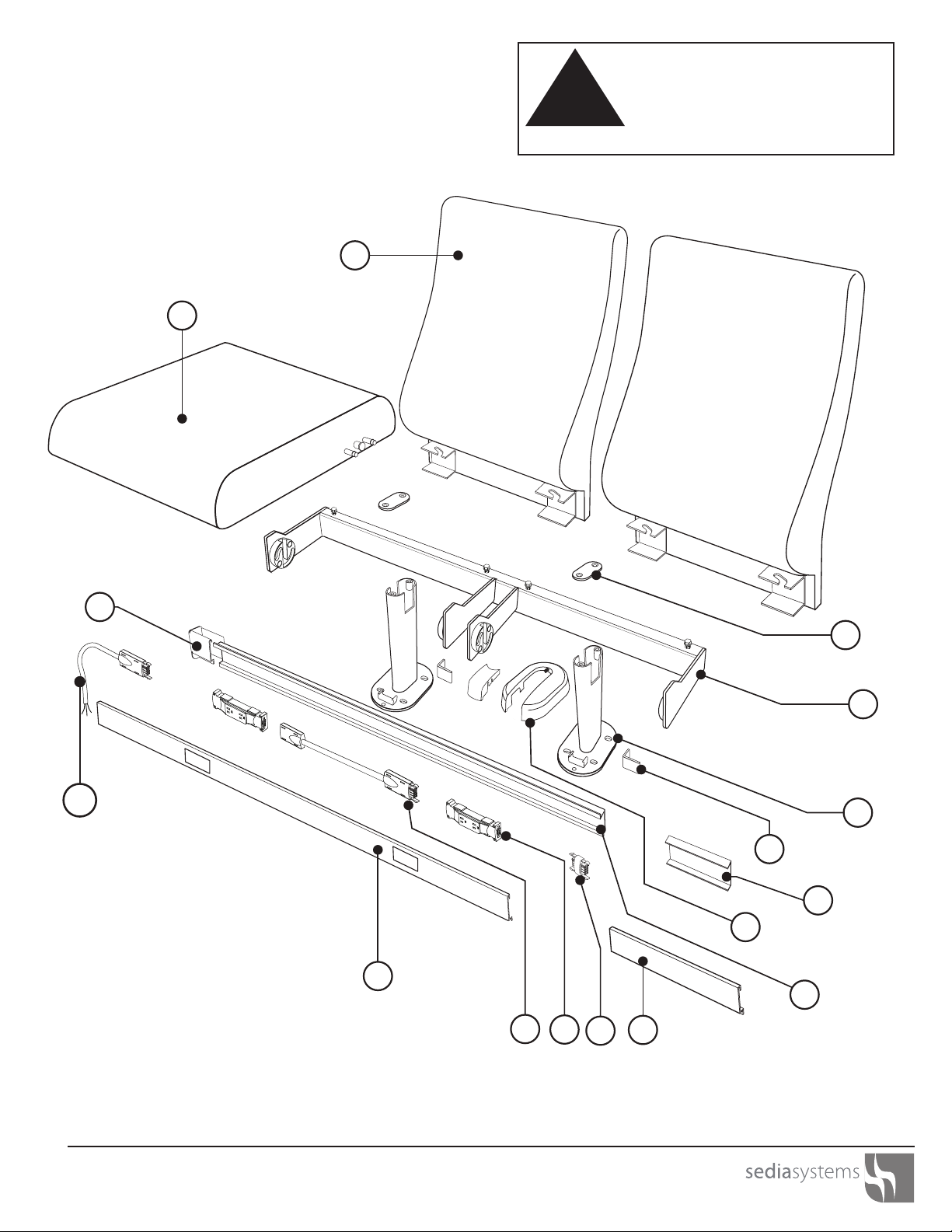
The FT20 auditorium seating system is intended to be used
in a commercial setting. The system consists of the
following components:
• Single Frame
• Beam Mount
• Riser Mount
• Seat
• Low Seat Back
• Mid Rise Seat Back
• High Seat Back
• Ultra Slim Seat Back
• Mesh Seat Back
• Power System
• Tablet Arm
Note: Read these assembly instructions carefully prior to
product installation. Electrically interconnected furnishings
must also be mechanically interconnected. Product failure
and personal injury may result if instructions are not
followed.
TOOLS REQUIRED
• Hammer drill and 1/4” masonary bit for concrete
anchor holes
• Drill and bit for pilot holes in wood floor
• #3 Phillips head screw driver
• #2 Phillips head screw driver
• Wrench Set
• Socket Set
• Allen Wrench
• 4’ Level
• 6-8’ Flexible straight edge 1/4 round or
equivalent
• 25 and 100’ Tape Measure
• Tailor’s Chalk
• FT20 Drill Template
IMPORTANT SAFETY INSTRUCTIONS
When using an electrical furnishing, basic precautions
should always be followed, including the following:
Read all instructions before installing the FT20 Chair
WARNING:
1. Risk of Electrical Shock - Connect this furnishing
to a properly grounded outlet only.
See Grounding Instructions.
2. Do not use outdoors.
3. Use this furnishing only for its intended use
described in these instructions. Do not use
attachments not recommended by the
manufacturer.
4. The maximum intended load for this seat is 300
pounds (102 Kilograms).
5. Functional Tablet Load - 20 Pounds (9 kg)
GROUNDING INSTRUCTIONS
This product must be connected to a grounded metal,
permanent wiring system, or an equipment-grounding
conductor must be run with the circuit conductors and
connected to the equipment-grounding terminal or lead
on the product.
Note: The power infeeds are to be connected to the
power source by a qualified electrician who must also
check the electrical integrity of the finished system
installation.
SAVE THESE INSTRUCTIONS
WHITE
GREEN/BARE
RED
BLACK
GROUND
HOT-2
HOT-1
NEUTRAL-1
CIRCUIT 1
I
CIRCUIT 2
II
WARNING
RISK OF FIRE OR ELECTRIC
SHOCK. DO NOT
ELECTRICALLY CONNECT
TO MORE THAN ONE SOURCE
OF SUPPPLY. ALL SOURCES
MUST BE DISCONNECTED
PRIOR TO ANY SERVICING
SEDIA SYSTEMS, INC.
CHICAGO, IL
*NOT FOR INTERRUPTING CURRENT*
FT20 Auditorium Seating
Assembly Instructions
CAUTION
!
Assemble units only as described herein. Failure to
do so may result in instability or assembly failure. All
screws, nuts and bolts must be tightened securely
and must be checked periodically after assembly.
Failure to assemble properly, or to secure parts may
result in personal injury.
INTRODUCTION
2
Wood Floors
• Minimum two layers of 3/4” thick plywood
• APA rated grade plywood
• Allow minimum embedment 1-1/2” with lag screws
• Use toggle bolt if less than 1-1/2” embedment
Concrete Floors
• 3000 psi concrete compressive strength
• 3“ thick free of obstruction for 1-1/2”
• Minimum anchor embedment 1-1/2”
Note: Warranty null and void if Sedia Systems FT20
seating product line is installed on flooring that does not
meet the minimum structural requirements stated above.
FLOOR FASTENER REQUIREMENTS
Wood Floors
• 3/8” x 2-1/2” lag bolts
• 3/8” flat washers
• (4) Bolt assemblies required per seat pedestal
Concrete Floors
• 1/4” x 2-5/8” concrete anchors
• 3/8” flat washers
• (4) Bolt assemblies required per seat pedestal
Site Preparation
1. Read and review the assembly instructions.
2. Review project drawings and layouts.
3. Locate floor center.
4. Locate row size line.
5. Draw size line for straight or radius rows.
6. Mark hole centerline for first chair.
7. Mark incremental hole centerline locations.
8. Use drill template to mark hole locations.
9. Use carpet punch at each hole location.
10. Locate and drill anchor holes into floor.
11. Vacuum holes to remove debris.
Chair Installation
12. Mount base to the floor with anchor bolts.
13. Align seat back bracket to base and slide to side.
14. Tighten seat attachment bolts with wrench.
15. Assemble seat by aligning pins with pivot disc slot.
16. Install seat pivot cap with seat in the down position.
17. Slide foot cover around post with slot facing front,
snap small cover onto base clip to lock in place.
Steps for Installing Power Option
Before Assembling Seat:
1. Drill pilot holes onto both sides of seat post as per
dimensions on layout.
2. Attach the raceway brackets to seat post.
3. Attach the raceway to the brackets.
4. Place the power whip into the raceway.
5. Attach the duplex outlet to the whip or jumper.
6. Attach the raceway end caps to each side.
7. Attach the raceway cover so the outlet module fills
the outlet opening in the cover.
8. Assemble seat by aligning pins with pivot disc slot.
9. Install seat pivot cap with seat in the down position.
10. Connect electrical whip to the main power source.
11. Mount row and seat numbering (optional).
12. Clean product and site for walk through.
Note: Dimensional spacing referenced is centerline to
center line unless otherwise noted.
FT20 Auditorium Seating
Assembly Instructions !
Assemble units only as described herein. Failure to
do so may result in instability or assembly failure. All
screws, nuts and bolts must be tightened securely
and must be checked periodically after assembly.
Failure to assemble properly, or to secure parts may
result in personal injury.
3
CAUTION
CAUTION
!
All power modules rated at 15A 120V 60HZ.
System capacity to be limited to 15A per
circuit.
No more than 12 outlets should be supplied by
one circuit.

1. All parts are lubricated for life.
2. Any service should be conducted by an authorized
service representative.
3. Perform periodic inspections for loose or broken parts.
LAMINATE:To clean the surface, use a damp cloth or
sponge and a mild soap or detergent. Difficult stains such
as coffee or tea can be removed using a mild household
cleaner and baking soda; mixing to achieve a paste
consistency. Use a stiff nylon bristle brush, scrubbing
(approx. 15-20 strokes) the affected area. Do not scrub so
as to mar (damage, scratch) the surface finish. Stubborn
stains that resist any of the above cleaning methods may
require the use of undiluted household bleach or nail polish
remover. Use a cotton ball saturated with bleach or nail
polish remover (acetone); gently rub the stain for up to two
minutes. Rinse thoroughly with warm water and wipe dry
using a soft cloth. This step may be repeated if the stain
appears to be going away and the color of the laminate
has not been affected.
CAUTION:
Prolonged exposure of the laminate and powder coat
surfaces to bleach will cause discoloration. Always rinse
laminate and powder coat surfaces after cleaning! Failure
to rinse after cleaning can cause damage; even if a small
amount of cleaning solution remains on the surface. A dry
residue may be invisible; however, moisture from cups or
drinks can reactivate it, and result in permanently etched
scars or stains over time.
Recommended Household Cleaners:
• Clorox®* • Formula 409® • Dawn® • Fantastik®
• Dow Bathroom Cleaner with Scrubbing Bubbles™
• Favor® • Windex® • Lestoil® • Glass Plus®
• Pledge® • Grease Relief® • Mr. Clean® • TOP JOB®
• Lysol® Brand Disinfectant Basin/Tub/Tile Cleaner
* Prolonged exposure can mar the surface
CAUTION:
Acidic or abrasive cleaners can damage laminate and
powder coat surfaces; do not use them. Drain cleaners
containing lye will permanently damage the laminate
surface. If you spill a drain cleaner, wipe it up immediately
and rinse several times with water. Hair, textile and food
dyes can cause permanent stains. If dye should happen to
spill, wipe it up immediately with dishwashing detergent or
an all-purpose cleaner. Wipe spills away promptly and rinse
several times with water.
Rust removers contain harsh chemicals, which will quickly
cause permanent damage. If a spill occurs, wipe off all
residues immediately, wash thoroughly with soapy water
and rinse several times. Steel wool and other abrasive pads
will damage the laminate and powder coat face. Do not use
them for cleaning and don’t store steel wool pads on your
countertop; the metal can rust and leave stains. Toilet bowl
cleaners contain harsh chemicals that can cause permanent
damage. If spills occur, wipe up immediately, wash surface
with soapy water and rinse several times.
The cleaners listed below can cause damage to the surface
of laminate:
Chemical Ingredient Synonymous Names
Hydrochloric Acid Muriatic Acid
Hydrogen Chloride
Sulfuric Acid Oleic Acid
Oil of Vitriol
Oleum
Hydrofluoric Acid Rust Remover
Phosphoric Acid Rust Remover
Sodium Hydroxide Caustic Soda
Caustic Soda Lye
Lye
Pumice (abrasive)
Remember, sharp objects can damage the surface of
laminate and powder coat surfaces, marring its beauty and
lowering wear and stain resistance. Although the laminate
and powder coat surfaces are somewhat resistant to
scratch and marring, they can be damaged, even under
normal use.
Laminate and powder coat surfaces may need occasional
dusting depending on where it’s used. To keep the surface
beautiful, use a non-oily furniture spray. (Remember to clean
the spray off several times a year to prevent build-up.)
Furniture polish can also help hide fine scratches in the
surface.
UPHOLSTERED FABRIC: Clean with water-based cleaning
agents, foam or pure water-free solvents. Vacuuming or light
brushing is recommended to prevent dust and soil buildup.
For answers to additional questions regarding care or
cleaning please contact Sedia Systems.
CAUTION
ROUTINE CARE AND MAINTENANCE
FT20 Auditorium Seating
Assembly Instructions !
Assemble units only as described herein. Failure to
do so may result in instability or assembly failure. All
screws, nuts and bolts must be tightened securely
and must be checked periodically after assembly.
Failure to assemble properly, or to secure parts may
result in personal injury.
4
CAUTION
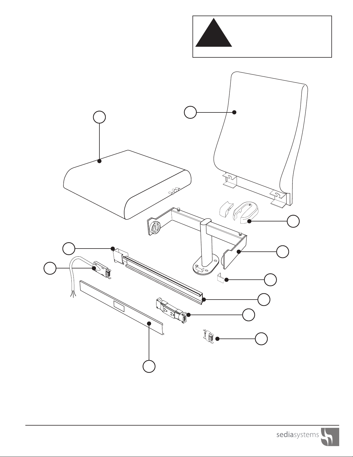
11
3
4
5
6
9
2
1
10
7
1. Seat
2. Seat Back
3. Foot Cover Assembly
4. Chair Base
5. Raceway Bracket
6. Raceway
7. Duplex Power Module
8. Duplex End Plug
9. Raceway Cover
10. Power Whip
11. Raceway End Cap
8
Standard Floor Mounted Chair CAUTION
!
Assemble units only as described herein. Failure to
do so may result in instability or assembly failure. All
screws, nuts and bolts must be tightened securely
and must be checked periodically after assembly.
Failure to assemble properly, or to secure parts may
result in personal injury.
5
FT20 Auditorium Seating
Assembly Instructions
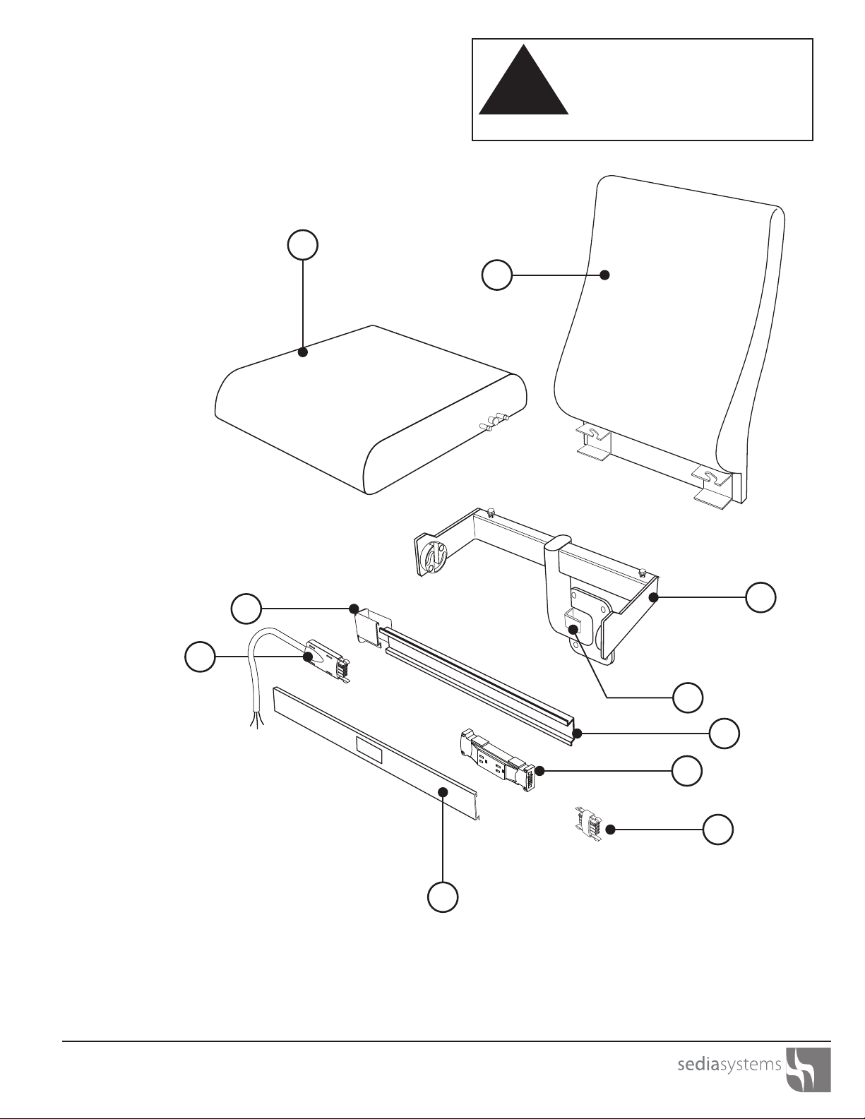
1. Seat
2. Seat Back
3. Riser Mount Assembly
4. Raceway Bracket
5. Raceway
6. Duplex Power Module
7. Duplex End Plug
8. Raceway Cover
9. Power Whip
10. Raceway End Cap
1
2
3
4
5
6
7
8
9
10
Standard Riser Mounted Chair CAUTION
!
Assemble units only as described herein. Failure to
do so may result in instability or assembly failure. All
screws, nuts and bolts must be tightened securely
and must be checked periodically after assembly.
Failure to assemble properly, or to secure parts may
result in personal injury.
6
FT20 Auditorium Seating
Assembly Instructions
1
2
3
4
6
5
7
9
10
11
14
16
8
1213
1. Seat
2. Seat Back
3. Beam Clamp
4. Beam Assembly
5. Pedestal Base
6. Raceway Bracket
7. Raceway Splicer
8. Foot Cover Assembly
9. Raceway
10 Raceway Spacer
11. Duplex End Plug
12. Duplex Power Module
13. Jumper Cable
14. Raceway Cover
15. Power Whip
16. Raceway End Cap
15
CAUTION
!
Assemble units only as described herein. Failure to
do so may result in instability or assembly failure. All
screws, nuts and bolts must be tightened securely
and must be checked periodically after assembly.
Failure to assemble properly, or to secure parts may
result in personal injury.
7
Standard Beam Mounted Chair
FT20 Auditorium Seating
Assembly Instructions
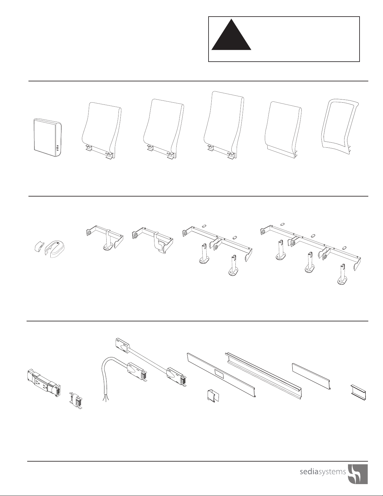
System Components
Jumper Cable
Lengths Based
on Layout Drawing
8 - 300 Inches
Cover
Lengths Based
on Layout Drawing
10 - 48 Inches
Raceway
Lengths Based
on Layout Drawing
17 - 72 Inches
Power Whip
72 - 300 Inches
Seat
20-26 inch widths
Low Back Mid Back (STD) High Back Ultra Slim Back
Single BaseFoot Cover Riser Mount Dual Beam Triple Beam
Duplex Module End CapEnd Plug
Mesh Back
SplicerSpacer
System Components CAUTION
!
Assemble units only as described herein. Failure to
do so may result in instability or assembly failure. All
screws, nuts and bolts must be tightened securely
and must be checked periodically after assembly.
Failure to assemble properly, or to secure parts may
result in personal injury.
8
FT20 Auditorium Seating
Assembly Instructions
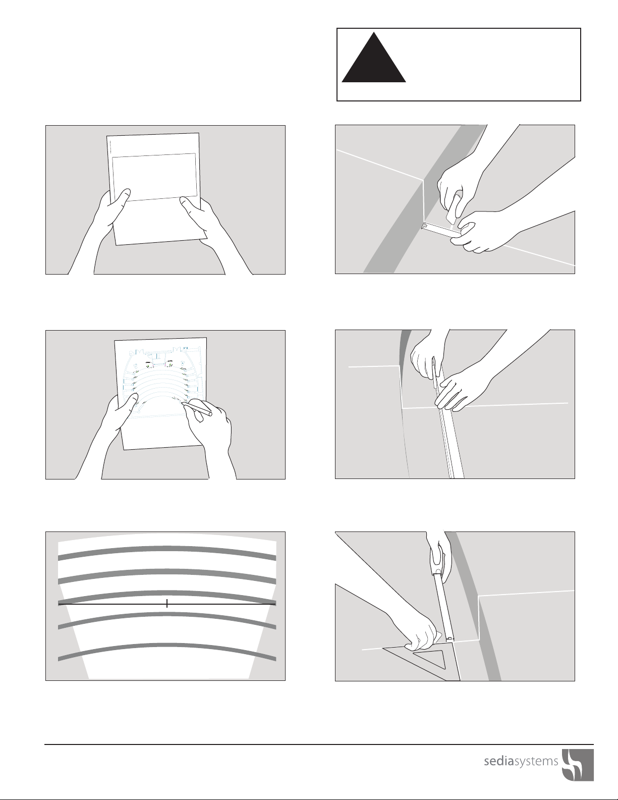
Site Preparation
Step 2: Refer to layout drawings and verify room
dimensions.
Step 3: Use tape measure to locate room center and
other reference dimensions and mark with chalk
Step 4: Use layout drawing to locate row size line from
back of riser and mark with chalk.
Step 5: Draw the size line. For radius floor, use
1/4 round or equivalent to get the radius size line.
Step 6: Mark hole locations of the first chair symmetric
the center line and according to the drawing.
FT20 AUDITORIUM SEATING
Assembly Instructions
May 2017
Step 1: Read and review the assembly instructions.
CAUTION
!
Assemble units only as described herein. Failure to
do so may result in instability or assembly failure. All
screws, nuts and bolts must be tightened securely
and must be checked periodically after assembly.
Failure to assemble properly, or to secure parts may
result in personal injury.
9
FT20 Auditorium Seating
Assembly Instructions

Site Preparation
Step 10: Drill holes using 1/4” x 4” concrete drill bit.
Concrete Floor - 4 holes, Wood Floor - 4 pilot holes
only.
Step 7: Mark all hole locations by incrementing
dimensions sequentially as per drawing.
Step 9: Punch carpet using hammer and punch.
Remove thread material and ensure drill area is free of
debris.
Step 8: Center drill template and mark hole locations. Step 11: Vacuum holes to remove wood/concrete
particles.
CAUTION
!
Assemble units only as described herein. Failure to
do so may result in instability or assembly failure. All
screws, nuts and bolts must be tightened securely
and must be checked periodically after assembly.
Failure to assemble properly, or to secure parts may
result in personal injury.
10
FT20 Auditorium Seating
Assembly Instructions

Chair Installation
Step 12: Align base and fasten with wood/
concrete anchors. Concrete Floor - 4 Bolts.
Wood Floor - 4 Bolts.
Step 13: Assemble back by sliding bracket onto frame
from rear side and sliding to the left.
Step 14: Tighten seat attachment bolts with box end
wrench.
Step 15: Assemble seat by positioning pins over the
slot in the pivot and lowering the seat.
Step 16: With the seat in the down position, insert the
pivot cap into the pivot disc so the notch is filled and
the cap snaps into place.
Step 17: Assemble the foot cover so the pin engages
the hole on the rear of the tube. Snap the cover clip
into place.
CAUTION
!
Assemble units only as described herein. Failure to
do so may result in instability or assembly failure. All
screws, nuts and bolts must be tightened securely
and must be checked periodically after assembly.
Failure to assemble properly, or to secure parts may
result in personal injury.
11
FT20 Auditorium Seating
Assembly Instructions

Power System Installation
Step 1: Before the seat is assembled, drill pilot holes
for the support brackets on side of tube. Dimensions
will be defined by the layout drawings.
Step 2: Assemble the brackets with metal cutting
screws and a phillips head screw driver.
Step 3: Center the raceway and assemble to the
brackets with #10-32 screws.
Step 4: Assemble the power whip into the raceway
through the hole in the back of the raceway.
Step 5: Attach the duplex outlet to the power whip
and add the end plug.
Step 6: Assemble the end caps to each side of the
raceway with #8x1/2” screws.
CAUTION
!
Assemble units only as described herein. Failure to
do so may result in instability or assembly failure. All
screws, nuts and bolts must be tightened securely
and must be checked periodically after assembly.
Failure to assemble properly, or to secure parts may
result in personal injury.
12
FT20 Auditorium Seating
Assembly Instructions

Power System Installation
Step 8: Assemble seat by positioning pins over the slot
in the pivot and lowering the seat.
Step 9: With the seat in the down position, insert the
pivot cap into the pivot disc so the notch is filled and
the cap snaps into place.
Step 7: Assemble the raceway cover so the duplex
outlet fills the hole. Attach with #8x1/2” screws.
Installing the Wrimatic Tablet Arm Option:
Assemble the Wrimatic arm to the post by attaching
the clamp plate to the bottom of the arm with (2)
provided M6 x 25mm socket head cap screws.
Tighten the screws to clamp the arm onto the post.
CAUTION
!
Assemble units only as described herein. Failure to
do so may result in instability or assembly failure. All
screws, nuts and bolts must be tightened securely
and must be checked periodically after assembly.
Failure to assemble properly, or to secure parts may
result in personal injury.
13
FT20 Auditorium Seating
Assembly Instructions
Table of contents
Other sedia systems Indoor Furnishing manuals


Popular Indoor Furnishing manuals by other brands


modway
modway EEI-3348 manual

American Signature
American Signature VCF IA34-455 Assembly instructions

Manual Thinking
Manual Thinking MT-WT L55 Assembly instructions

SHOR-LINE
SHOR-LINE Blue-Line 903.1530.04 Guide

Kvik
Kvik P15675 Assembly instructions

FMD Furniture
FMD Furniture MEGA 2 248-002 Assembly instructions

modway
modway KING BED FRAME MOD-5433 Assembly instructions

Universal Furniture
Universal Furniture 628355 instruction sheet

Balmani
Balmani Fila Wall Unit installation guide

Broyhill
Broyhill LEGACY CASTLE PINES KVS9433 Assembly instruction

Ideal-Standard
Ideal-Standard Conca T4580Y1 Installation

Venjakob
Venjakob NEXT LEVEL 3000 Assembly instruction