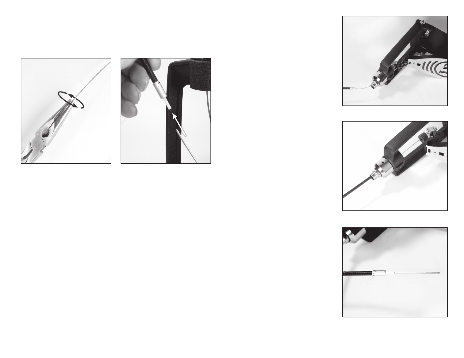
LP LP1501 User manual

LP1501 Cajon Pedal
Cable Replacement
Instructions
LP1501-CK

STEP 1
Pull the top end of the tension spring upwards and away from the beater frame, and remove the spring
attachment hanger from the black bearing ring, as shown in Figures 1.1 and 1.2. If it is too difficult to
pull the spring upwards, try loosening the tension adjustor at the bottom of the spring.
Figure 1.1
Figure 2.1
Figure 1.2
Figure 2.2
STEP 2
Use the included the 2mm hex key to loosen both retention screws on the cable attachment barrel
(see Figure 2.1). You do not need to pull the screws all the way out of the barrel. Once you have
loosened the retention screws, the cable may fall out of the barrel on its own (see Figure 2.2), causing
the footboard to drop. TO AVOID INJURY, KEEP YOUR FINGERS CLEAR OF THE FOOTBOARD WHILE
YOU ARE LOOSENING THE RETENTION SCREWS.
2 3
Pull up
on spring
Tension
adjustment
Loosen set screws
If old cable
cannot be
pulled out,
cut here...
...then twist apart
just above set
screws and
replace bottom
piece
You will need the following items to install your replacement cable:
INCLUDED WITH REPLACEMENT KIT:
• Steel cable
• Black, vinyl cable housing
• 2mm hex key
• Bottom piece for Cable Attachment Barrel
NOT INCLUDED:
• Adjustable crescent wrench or ¾-inch wrench
• Needle-nose pliers
• Small wire cutters (if needed)

FOR STUCK CABLES
During manufacturing, a small amount of glue is used on the set screws to strengthen the cable
attachment. When you loosen the set screws, if the cable does not fall out of the attachment
barrel on its own, try to pull the cable end out of the barrel. If the cable will not pull out, follow
the instructions below. (See Figure 2.1 on previous page):
a. Use wire cutters to cut the cable just below the attachment barrel.
b. Twist and unscrew the two halves of the attachment barrel. Remove the lower half of
the barrel with the remaining cable scrap stuck inside, and completely discard it.
c. Screw the included new lower half onto the attachment barrel, and proceed with the
rest of these instructions.
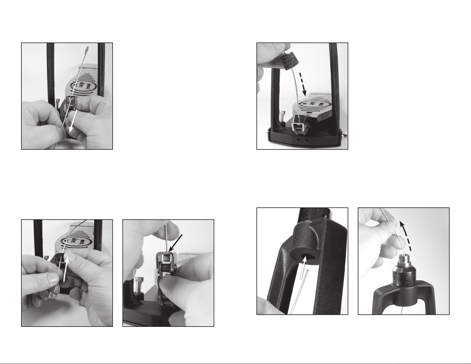
STEP 3
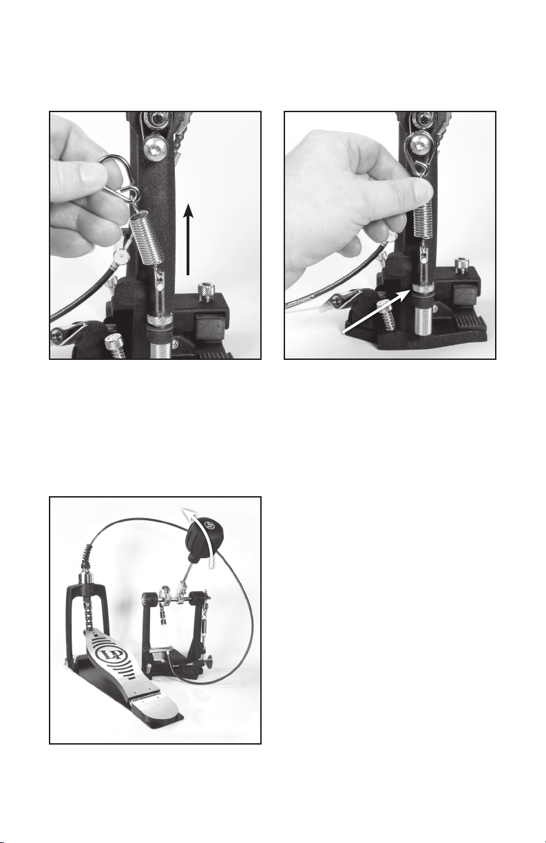
Pull the cable end, including the cable housing (the black, vinyl covering around the steel cable),
out of the angle guard, as shown in Figures 3.1 and 3.2. The beater frame assembly should now be
completely disconnected from the rest of the pedal. Set aside the beater frame assembly.
Figure 3.1
Figure 4.1
Figure 4.3
Figure 3.2
Figure 4.2
STEP 4
Using a ¾-inch wrench or an adjustable crescent wrench, loosen the black nut at the bottom of the
cable sheath (see Figures 4.1 and 4.2).
WARNING: Attempting to loosen this nut with any tool other than a wrench could leave scratches and
gouge marks on the surface of the nut. After loosening, twist the nut all the way off the screw top.
Then, slide the black sheath all the way off the cable (see Figure 4.3) and put it aside.
4 5
Pull
Pull
Loosen nut
Slide

STEP 5
Pull the small, black sheath stopper out of the screw top (see Figures 5.1 and 5.2). If it is difficult to
pull out the stopper with your bare hands, try pulling it out with a pair of needle-nose pliers.
Figure 5.1
Figure 6.1
Figure 8.1
Figure 5.2
Figure 7.1
Figure 6.2
Figure 8.2
STEP 6
Grasp the steel cable with one hand, just above the footboard chain attachment (see Figure 6.1).
Then, grasp the cable housing with the other hand. Pull in opposite directions and slide the cable
housing all the way off the steel cable (see Figure 6.2). Discard the old cable housing.
STEP 7
Slide the felt washer all the way off the cable
(see Figure 7.1) and set it aside.
STEP 8
Detach the existing cable from the footboard chain using ONE of these two methods:
With needle-nose pliers:
a. Use a pair of needle-nose pliers to grab the cable stopper inside the footboard chain
attachment link.
b. Twist the cable stopper gently with the pliers, so that its circular sides are parallel to the sides
of the chain attachment link, as shown in Figure 8.1. Once the stopper is in this position, you
can slide it out the backside of the chain attachment link and away from the footboard, as
shown in Figure 8.2.
Or with wire cutters:
a. Use wire cutters to grab the cable just above the cable stopper, inside the footboard chain
attachment link (see Figure 8.1).
b. Cut the cable stopper off the steel cable and discard it.
6 7
Pull Slide
Slide apart
Grasp cable
here Twist stopper to this
position and slide out...
...or c ut he re
Remove cable
Slide

Figure 10.1
Figure 12.1
Figure 9.1 Figure 11.1
Figure 10.2
Figure 12.2
STEP 9
Pull the entire steel cable through the chain attachment link, and all the way out of the channel at the
top of the pedal frame (see Figure 9.1). Discard the old cable.
STEP 11
Slide the felt washer onto the new cable, all the way down to the footboard chain, as shown in
Figure 11.1.
STEP 10
Thread the NEW steel cable up through the hole in the footboard chain attachment link, as shown
in Figure 10.1. Pull the cable all the way through the hole, until the cable stopper catches inside the
attachment link. Push gently on the cable stopper until it is completely inside the attachment link and
catches, as pictured in Figure 10.2.
STEP 12
Insert the new cable underneath the channel at the top of the footboard frame, as shown in Figure
12.1. Push the cable up through the channel and pull it out through the top hole, as shown in Figure
12.2.
8 9
Remove cable
Insert cable
Pull cable through
Stopper will catch here
Slide

Figure 13.1 Figure 13.2
Figure 14.2
Figure 14.2
Figure 14.1
STEP 13
If the cable has any fraying at the end, grasp the frayed steel fibers with needle-nose pliers and gently
squeeze and twist the steel fibers together, as shown in Figure 13.1. This will make it easier to insert
the cable end into the housing. NOTE: Make sure there are no frayed steel fibers caught outside the
cable housing, in order to avoid damaging the cable or the housing. Thread the end of the cable into
the plastic inner layer of the NEW black cable housing, as pictured in Figure 13.2.
STEP 14
Once the steel cable is threaded into the
cable housing, turn the entire footboard
frame assembly on its side, so the weight
of the footboard does not pull downward on
the attached cable (see Figure 14.1).
Slide the housing all the way down the
cable, until it goes into the screw top and
stops, as in Figure 14.2. At the other end
of the housing, the steel cable should be
exposed as in Figure 14.3.
10 11
If cable is frayed, grasp
with pliers and twist
Thread cable
into housing
Cable should stop inside screw top
End of steel cable should extend
out from end of cable housing

Figure 15.1
Figure 16.1
Figure 15.3
Figure 16.3
Figure 15.2
Figure 16.2
STEP 15
Stand the footboard frame upright. Insert the housed cable into the smooth end of the sheath stopper
(see Figure 15.1). Then, slide the stopper all the way down the cable (see Figure 15.2). Push the
smooth end of the stopper into the screw top, until the notches prevent it from going any further (see
Figure 15.3).
STEP 16
Insert the housed cable into the wide end of the black cable sheath (see Figure 16.1). Slide the sheath
all the way down the cable (see Figure 16.2), and twist the black nut onto the screw fitting (see Figure
16.3). Use the wrench to firmly tighten the nut.
12 13
Insert cable
Slide
Notches will catch here
Insert cable
Slide
Tighten nut

Figure 17.1 Figure 18.1
Figure 18.3
Figure 17.2 Figure 18.2
Figure 18.4
STEP 17
Stand the beater frame upright. Insert the housed cable into the underside hole of the angle guard, as
shown in Figure 17.1. Maneuver the housed cable so that the silver fitting at the end slides into the hole
of the angle guard and stops. Pull only the steel cable with the plastic inner housing through the angle
guard and out the top hole. The end result should look like Figure 17.2. IMPORTANT: leave a little slack
at the other end of the cable, where it attaches to the footboard chain.
STEP 18
Rotate the cam and beater to the proper angle, so that the beater chain is laying OVER THE TOP of the
cam. (In the photos below, Figure 18.1 is correct, Figure 18.2 is incorrect.) Thread the steel cable into
the bottom hole of the cable attachment barrel, as pictured in Figure 18.3. Push the cable in as far as
it will go. Use the hex key to tighten the set screws on the attachment barrel. The cable should now be
locked in place and the end result should look like Figure 18.4.
14 15
Insert cable
Pull through Chain hanging over cam Chain hanging straight down underneath cam
CORRECT INCORRECT
Insert cable
Tighten set screws

Figure 19.1
Figure 20.1
Figure 19.2
STEP 19
Grasp the attachment hanger on the beater tension spring. Pull upward on the spring and slide the
hanger back on to the black bearing ring, as shown in Figures 19.1 and 19.2. If you loosened the spring
tension adjuster in Step 1, you should now retighten it.
STEP 20
Your cajon pedal should now look similar to Figure 20.1. Push down on the footboard with your hand
to test the pedal. The footboard chain should pull downward on the cable, rocking the beater forward.
When you take your hand off the footboard, the beater should spring back to its original position. Your
pedal now has a sturdy and secure new cable and is ready for use.
16
Pull up
on spring
Tension
adjustment
Press down on
footboard to test
Beater motion
© 2022 Latin Percussion.
LP1501-CK
This manual suits for next models
1