Seedsware InfoSOSA Series 7 User manual

- 1 - 14A4A4-00090E-3
InfoSOSA™ Series
Touchscreen Display
Model “7”
Instruction Manual
Seedsware Corporation
http://www.seedsware.co.jp/global/

- 2 - 14A4A4-00090E-3
Table of Contents
Table of Contents.......................................................................................................................................... 2
1. Introduction............................................................................................................................................ 4
2. Notes..................................................................................................................................................... 4
3. Precautions for Safe Use ...................................................................................................................... 4
3-1 Warnings...........................................................................................................................................................5
3-2 Cautions............................................................................................................................................................6
3-3 Handling of LCD Panels....................................................................................................................................7
3-4 Handling of Batteries.........................................................................................................................................7
3-5 Handling of Image Files.....................................................................................................................................7
4. Model “7” Products ................................................................................................................................ 8
4-1 General Specification........................................................................................................................................8
4-2 Introduction Sample Kit.....................................................................................................................................8
5. Packaged Contents............................................................................................................................... 9
5-1 Standard Specification......................................................................................................................................9
5-2 Introduction Sample Kit...................................................................................................................................10
6. Part Names and Their Functions......................................................................................................... 13
6-1 Main Unit.........................................................................................................................................................13
6-2 Battery Board (IS-BT-01).................................................................................................................................17
6-3 Power Cable (ISCBL-S01-001).......................................................................................................................17
6-4 Power Cable (For AC Adapter)........................................................................................................................17
6-5 Communication Cable for SIO1 (ISCBL-S02-001)...........................................................................................18
6-6 Battery Cable (ISCBL-S04-001)......................................................................................................................18
7. Installation and Wiring......................................................................................................................... 19
7-1 Installation.......................................................................................................................................................19
7-2 Open Frame Type Installation.........................................................................................................................19
1) Open Frame Type Panel Opening Example..................................................................................................19
2) Open FrameType Panel Mounting Procedures.............................................................................................23
3) Open FrameType Angle Installation Diagram................................................................................................24
7-4 Wiring Procedure ............................................................................................................................................26
Wiring Location....................................................................................................................................................26
1) Connecting Unit to Power .............................................................................................................................28
2) Connecting to Communication Cable............................................................................................................29
3) Connecting Design Sheet Key Tail................................................................................................................31
4) Connecting with Battery Board......................................................................................................................32
7-5 Mounting Conditions .......................................................................................................................................33
8. Starting the InfoSOSA......................................................................................................................... 34
9. Starting the Development Tool (InfoSOSA Builder) ............................................................................ 34
10. Maintenance........................................................................................................................................ 35
10-1 Display Maintenance.....................................................................................................................................35

- 3 - 14A4A4-00090E-3
10-2 Regular Inspections ......................................................................................................................................35
11. Warranty and Repairs ......................................................................................................................... 36
11-1 Repairs .........................................................................................................................................................36
11-2 Warranty.......................................................................................................................................................36
11-3 Production Discontinuance............................................................................................................................36
11-4 Repair Warranty............................................................................................................................................36
12. Others ................................................................................................................................................. 37
Appendix Outline Diagrams

- 4 - 14A4A4-00090E-3
1. Introduction
Thank you for choosing Seedsware products. Please read this manual carefully and use our product
correctly.
This document describes the manual of the 7” model touchscreen display.
2. Notes
■Reproduction and/or duplication of this product and/or this manual, in any form, in whole or in
part, without permission is strictly prohibited.
■Contents of this product and/or this manual are subject to change without previous notice.
■Although all efforts have been made to ensure the accuracy of this product and/or the contents of
this manual, should you notice any errors or have any questions, feel free to contact and notify
us.
■Seedsware shall not be held liable in any way for damages or losses, nor be held responsible for
any claims by a third party as a result of using this product.
3. Precautions for Safe Use
Precautions are noted in this manual in order for the product to be used safely. Read this manual
along with other related manuals carefully to understand the correct handling and functions of the
InfoSOSA.
Safety Symbol Legends
Safety symbols listed below are noted throughout this manual for the TM to be used correctly. These
symbols stand for very important safety information as noted below:
Warning
Indicates a procedure, condition, or statement that, if not strictly observed, could result in
severe human injuries or loss of life.
Caution
Indicates a procedure, condition, or statement that, if not strictly observed, could result in
human injuries or property damage.
Indicates a procedure, condition, or statement that is strictly prohibited for correct use of the
equipment. (Forbidden)
Indicates a procedure, condition, or statement that must be strictly followed for correct use of
the equipment. (Mandatory)

- 5 - 14A4A4-00090E-3
3-1 Warnings WARNING
Warnings for Design
Designing switches that might cause human injuries and/or property damage on the touch screen is strictly
prohibited. Unintentional output signals due to malfunction of the main body, units, and/or cables, etc. can
cause serious injuries. Design the system so that switches with major functions are equipped on other
devices.
Designing safety related switches on the InfoSOSA is prohibited. Switches related to safety, such as
emergency stop switches, should be made on a different hardware.
Design the system so the device will not malfunction due to communication abnormalities between the IS and
the host controller. Failure to follow may result in injury to the human body or damage to properties.
Do not use InfoSOSA as a major warning system that may cause injuries/ serious material damages, and or
production stoppage. Control devices related to critical warning displays and warnings should be structured on
an independent, redundant hardware system or a mechanical interlock.
InfoSOSA is not intended for use for aircraft equipment, aerospace instruments, trunk line communication
equipment, nuclear power control equipment, and medical equipment that concerns life support, and or other
equipment that concerns high reliability and safety. It cannot be used for these purposes.
When using the InfoSOSA for purposes that concern high reliability and safety functions and accuracy such
as transport equipment (trains, automobiles, ship, etc.), crime/disaster prevention devices, various safety
devices, and medical equipment that does not concern life support, be sure to have safety features including
redundancy and false operation prevention measures incorporated into the entire system.
Display will black out when the backlight goes out. If mistakenly operated in this condition, it might result in
improper operation. Do not design touch-switches that might cause human injuries and material damages on
the InfoSOSA.
Phenomenon as below will occur when the backlights go out:
(1) Screen will go out even if the Backlight OFF function is not set.
(2) Display does not recover at touch after the backlight goes off as well as the display.
Warnings for Handling
Do not modify/disassemble the TM. It may cause fires and/or electric shocks
Do not use around flammable gas. It may cause explosions.
Do not put any kind of liquid, such as water, and metals into the product. It may cause fire and/or electrical
shocks.

- 6 - 14A4A4-00090E-3
Warnings for Wiring
For wiring and installation, please refer to the manual and specifications in order to conduct it correctly. It may
cause fires and/or electric shocks.
Before installing the power cable, make sure power is not being supplied from power source. It may cause
electrical shock.
Do not use power voltage other than what is specified. It may cause fires and/or electric shocks.
3-2 Cautions Cautions
Cautions for Disposal
When disposing the product, please treat it as industrial waste.
Precautions for Safe Use
(1) Do not press down on display with strong power or hard objects. It may break the LCD panel and cause
injuries.
(2) Please use this product within the specified ambient temperature and humidity range. If not used
properly, it may cause malfunctions.
(3) Do not press down on the display area of InfoSOSA with sharp objects such as mechanical pencils or
drivers. It may damage the display.
(4) If the surface of InfoSOSA gets dirty, wipe with a dry, soft cloth damped with a neutral detergent then
wrung dry. Do not use thinner or organic solvents.
(5) Do not use in areas where rapid temperature change can cause condensation. It may cause
malfunctions.
(6) In order to prevent product temperature from rising, do not use in areas where heat can be trapped. Also
prevent storing in areas of high temperature.
(7) Do not use or store InfoSOSA in locations exposed to direct sunlight, fine particles, oil smoke and
steam.
(8) Do not use or store all precision equipment where shock or vibration can be applied.
(9) Do not use or store in areas where gasified chemicals are diverged into the air, or where chemical
contamination can occur.
(10) Be sure to take backups of the data in case of an unintended accident.
(11) When using power source with slow rise-time and fall-time, it may not operate correctly. Be sure to drop
the voltage to 0V when turning the power back on after once turning off the power, before turning on the
power. It may not boot correctly.
(12) Please be warned that applications that require for one point to be pressed for a prolonged time may
cause failures due to the touch screen's structural characteristics.
(13) Touch screen coordinates may shift due to aging or depending on its operating environment. Conduct
calibration of the touchscreen to correctly set the coordinates.

- 7 - 14A4A4-00090E-3
3-3 Handling of LCD Panels
(1) The LCD display contains skin-irritating materials. If liquid materials flow out due to damage
and comes in contact with skin, wash the area under running water for at least 15 minutes. If
it gets into the eyes, wash under running water and consult a doctor.
(2) The LCD display might have uneven brightness according to the contents being displayed.
This is not a malfunction.
(3) Minute spots (dark or bright) may occur in the LCD display elements. This is a basic
characteristic of the LCD display and not a malfunction.
(4) When LCD display is viewed outside the specified view angel, the color might seem different.
This is a basic characteristic of the LCD display and not a malfunction.
(5) When displaying a same image for a long period of time, it might cause an image lag. This is
a basic characteristic of the LCD display and not a malfunction.
In order to avoid image lags, change the image displayed periodically and do not display the
same image for a long period of time.
3-4 Handling of Batteries
(1) Do not recharge the batteries.
(2) When disposing, tape the terminal and make sure it is insulated. It not insulated, it may
cause heat, explosions or ignite.
(3) Confirm the +/- polarity and make sure the it is connected in the correct direction.
(4) Do not store in areas exposed to direct sunlight, with high temperature and/or high humidity.
3-5 Handling of Image Files
When using image files, please use ones that were created by individual users.
Using and distributing, without permission, files protected by copyright is strictly prohibited by law.
Please note some free materials might have using restrictions.

- 8 - 14A4A4-00090E-3
4. Model “7” Products
4-1 General Specification
Model
Specification Distinction*
IS701-3SSN2-001
3.5”
QVGA(320 x 240)
4,096colors
Open Frame
1 language
IS711-4SSN3-001
4.3”
WQVGA(480 x 272)
4,096 colors
Open Frame
1 language
IS701-5SSN1-001
5.7”
QVGA(320 x 240)
65,536 colors
Open Frame
1 language
IS701-5SSN1-101
5.7”
VGA(640 x 480)
65,536 colors
Open Frame
1 language
* Product specification listed items:
“Display size/Resolutions/Displayed colors/Chassis type/ Maximum support language”
・1 language (Maximum of 1 system font language can be used.)
Specification varies according to the model.
This specification provides information according to each distinctive model.
4-2 Introduction Sample Kit
Tool for development will be included with the Standard specification article.
Model
Specification Distinction*
IS701-3SSN2-001-KIT
3.5”
QVGA(320 x 240)
4,096colors
Open Frame
1 language
IS711-4SSN3-001-KIT
4.3”
WQVGA(480 x 272)
4,096 colors
Open Frame
1 language
IS701-5SSN1-001-KIT
5.7”
QVGA(320 x 240)
65,536 colors
Open Frame
1 language
IS701-5SSN1-101-KIT
5.7”
VGA(640 x 480)
65,536 colors
Open Frame
1 language
* Product specification listed items:
“Display size/Resolutions/Displayed colors/Chassis type/ Maximum support language”
・1 language (Maximum of 1 system font language can be used.)
Specification varies according to the model.
This specification provides information according to each distinctive model.
Note: Introduction Sample kit unit specification is the same as that of the standard specification unit.

- 9 - 14A4A4-00090E-3
5. Packaged Contents
Below items are included in the package. Please make sure there no missing items before use.
Although all efforts have been made to assure the quality and packaging before shipment, if you notice
any damages or missing items, please notify us before use.
5-1 Standard Specification
■3.5”Open Frame
*Maximum number of units that could be stored: 10 units
■4.3”Open Frame
*Maximum number of units that could be stored: 10 units
■5.7”Open Frame
*Maximum number of units that could be stored: 5 units
Main Unit 10 units/box*
Main Unit 10 units/box*
Main Unit 5 units/box*

- 10 - 14A4A4-00090E-3
5-2 Introduction Sample Kit
■3.5”Open Frame
Main Unit 1pc
Accessory List 1pc
Communication Cable for SIO1(ISCBL-S02-001)1pc
Power Cable(ISCBL-S01-001)1pc
AC Adapter 1pc
Power Cable (for AC Adapter) 1pc
CD (Below files are include in the CD) 2pcs*
Product Specification
Instruction Manual
InfoSOSA Installation Guide
InfoSOSA Builder Installer
InfoSOSA Builder Operation Manual
Reference Manual
Host Communication Tester Instruction Manual
Release Note
User Registration Form
* Includes 2 CDS: 1 Japanese version and 1 English version.

- 11 - 14A4A4-00090E-3
■4.3”Open Frame
Main Unit 1pc
Accessory List 1pc
Communication Cable for SIO 1(ISCBL-S02-001)1pc
Power Cable(ISCBL-S01-001)1pc
AC Adapter 1pc
Power Cable (for AC Adapter) 1pc
CD (Below files are include in the CD) 2 pcs*
Product Specification
Instruction Manual
InfoSOSA Installation Guide
InfoSOSA Builder Installer
InfoSOSA Builder Operation Manual
Reference Manual
Host Communication Tester Instruction Manual
Release Note
User Registration Form
* Includes 2 CDS: 1 Japanese version and 1 English version.

- 12 - 14A4A4-00090E-3
■5.7”Open Frame
Main Unit 1pc
Accessory List 1pc
Communication Cable for SIO 1 (ISCBL-S02-001)1 pc
Power Cable(ISCBL-S01-001)1 pc
AC Adapter 1pc
Power Cable (for AC Adapter) 1 pc
Battery Board (IS-BT-01) 1pc
Battery (CR2032) 1pc
Battery Cable (ISCBL-S04-001) 1 pc
CD (Below files are include in the CD) 2pcs*
Product Specification
Instruction Manual
InfoSOSA Installation Guide
InfoSOSA Builder Installer
InfoSOSA Builder Operation Manual
Reference Manual
Host Communication Tester Instruction Manual
Release Note
User Registration Form
* Includes 2 CDS: 1 Japanese version and 1 English version.
+

- 13 - 14A4A4-00090E-3
6. Part Names and Their Functions
6-1 Main Unit
■3.5”Open Frame
■Front Side
■Back Side
Display/ Touch Screen
Display screen images, input by
touchscreen.
Frame
-Use when mounting to
devices.
-Connected to GND (Signal
GND) inside the unit.
Power Connector
Connects power cable.
Serial Port (SIO2)
Connects communication cables.
Adjustment connector
(Internal use)
-Internal use only.
Do not attempt to connect
anything.
-May not be mounted without prior
notice.
DIP SW
Set at shipment.
Do not change shipment to
avoid malfunctions
Serial No. Label
Product Label
Applied inside of sheet metal.
Serial Port (SIO1)
Connects communication cables.
ON
2
1
3
4
- 14 - 14A4A4-00090E-3
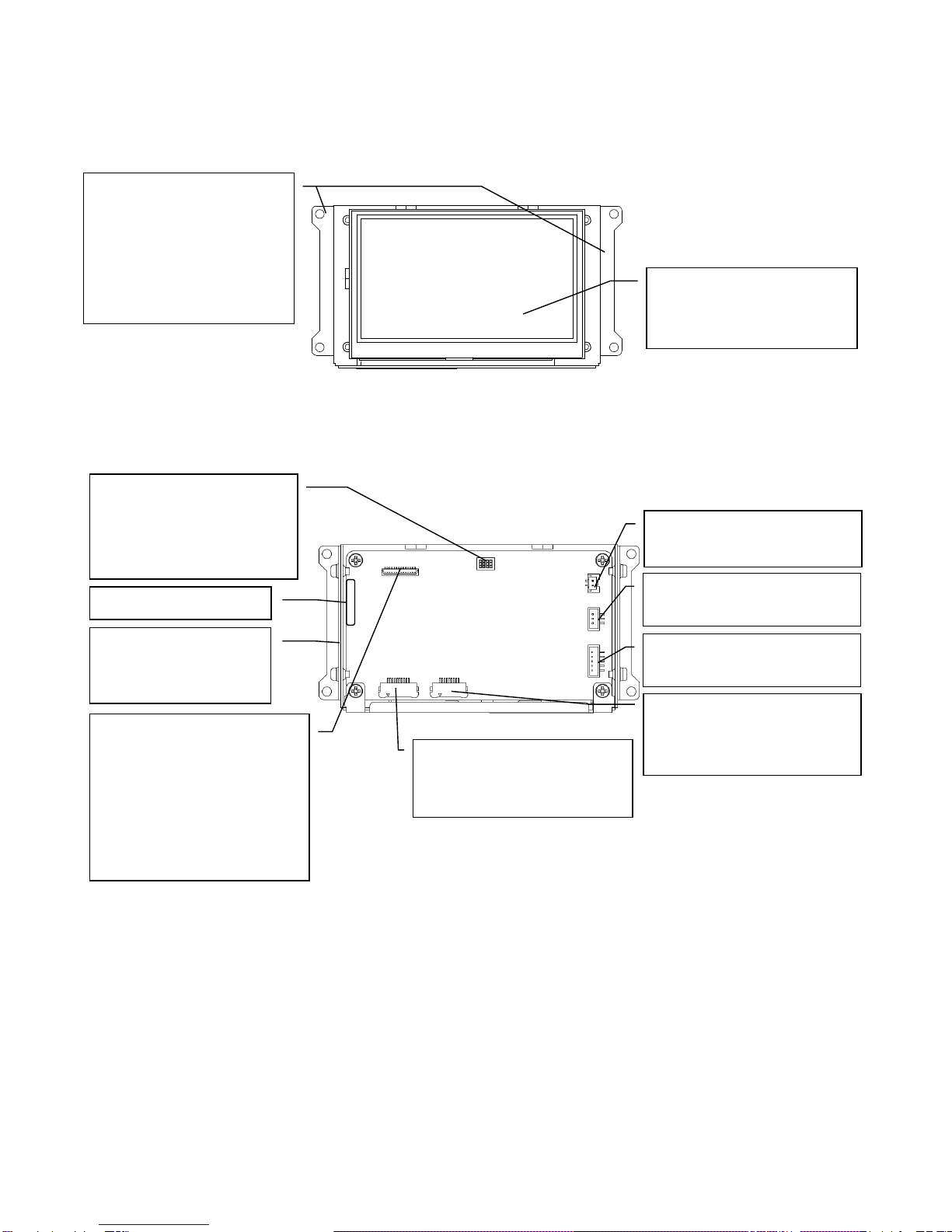
■4.3”Open Frame
■Front Side
■Back Side
Display/ Touch Screen
Display screen images, input by
touchscreen.
Angle
-Use when mounting to devices.
-Tighten screws on sides to
install and adjust height
-Connected to GND (Signal
GND) inside the unit.
Power Connector
Connects power cable.
Adjustment connector
(Internal use)
-Internal use only.
Do not attempt to connect
anything.
-May not be mounted without prior
notice.
DIP SW
Set at shipment.
Do not change shipment to
avoid malfunctions
Sheet Key Interface (for Switch)
Connect tail for switch of design
sheet key.
Serial No.Label
Product Label
Applied inside of sheet
metal.
Serial Port (SIO1)
Connects communication cables.
Sheet Key Interface (for LED)
Connect tail for LED of design
sheet key.
Serial Port (SIO2)
Connects communication cables.

- 15 - 14A4A4-00090E-3
■5.7”QVGA Open Frame
■Front Side
■Back side
Display/ Touch Screen
Display screen images, input by
touchscreen.
Angle
-Use when mounting to devices.
-Tighten screws on sides to install
and adjust height
-Connected to GND (Signal GND)
inside the unit.
DIP SW
Set at shipment.
Do not change shipment to avoid
malfunctions
Battery Port
Connects battery board or battery
Adjustment connector
(Internal use)
-Internal use only.
Do not attempt to connect
anything.
-May not be mounted without prior
notice.
Power Connector
Connects power cable.
Serial No. Label
Model Label
Applied on side of sheet metal
Sheet Key Interface (for
Switch)
Connect tail for switch of design
sheet key.
LCD Connection
Connection made by us.
Do not touch to avoid damage to
connector or the flexible cable of
LCD.
Serial Port (SIO1)
Connects communication cables.
Sheet Key Interface (for LED)
Connect tail for LED of design
sheet key.
Serial Port (SIO2)
Connects communication cables.

- 16 - 14A4A4-00090E-3
■5.7”VGA Open Frame
■Front Side
■Back side
Display/ Touch Screen
-Display screen images, input by
touchscreen.
-Touchscreen for touchscreen
compliant models only.
DIP SW
Set at shipment.
Do not change shipment to avoid
malfunctions
Battery Port
Connects battery board or battery
Serial Port (SIO1)
Connects communication cables.
Power Connector
Connects power cable.
Serial No. Label
Sheet Key Interface (for LED)
Connect tail for LED of design
sheet key.
Sheet Key Interface (for Switch)
Connect tail for switch of design
sheet key.
Product Label
Applied inside of sheet metal.
Angle
-Use when mounting to devices.
-Tighten screws on sides to install
and adjust height
-Connected to GND (Signal GND)
inside the unit.
・
Serial Port (SIO2)
Connects communication cables.

- 17 - 14A4A4-00090E-3
6-2 Battery Board (IS-BT-01)
■5.7”
*1pc included in the Introduction Sample Kit.
6-3 Power Cable (ISCBL-S01-001)
■3.5”/ 4.3”/ 5.7”
*1pc included in the Introduction Sample Kit.
6-4 Power Cable (For AC Adapter)
■3.5”/ 4.3”/ 5.7”
*1pc included in the Introduction Sample Kit.
Housing
Connects to main unit connector
1Pin (Red)
Connects to 5VDC
2 Pin (Black)
Connects to GND (0V)
Battery Holder
Insert batteries
Interface for connecting to unit
Connects to unit
Housing
Connects to main unit connector
DC Jack
Connects to AC adapter plug

- 18 - 14A4A4-00090E-3
6-5 Communication Cable for SIO1 (ISCBL-S02-001)
■3.5”/ 4.3”/ 5.7”
*1pc included in the Introduction Sample Kit.
6-6 Battery Cable (ISCBL-S04-001)
■5.7”
*1pc included in the Introduction Sample Kit. (5.7” only)
Housing
Connects to main unit serial port
Dsub
Connects to RS232 port of
the host (PC)
Housing
Connects to battery interface of
main unit side.
Housing
Connects to interface for
connecting to main unit of battery
board side.

- 19 - 14A4A4-00090E-3
7. Installation and Wiring
7-1 Installation
■3.5”/ 4.3”/ 5.7”
•Make sure that power is not applied when installing and/or wiring.
•Refer to the panel opening example and the attached outline diagrams when designing the
chassis.
•Design the chassis so that there will be no contorting or deformation when installing.
•Make sure cables from the LCD do not come in contact with the structure and is not subject to
stress.
•When using the design sheet key, a tail opening that suits the design sheet key is necessary.
7-2 Open Frame Type Installation
1) Open Frame Type Panel Opening Example
■3.5”Open Frame
Below is the panel opening dimension example for when applying sheets and etc. to the surface by
opening the entire touch screen surface.
Design the chassis accordingly to the actual installing method.
*Diagram from the front side of panel (panel thickness: 1.6mm or less).
Center of Display
表示部
センター
2×2-φ 3 Half punch h=0.5
Convex surface (Opposite side also)
2×2-M3 (Opposite side also)
Screw depth 5mm or less
Mounting Panel

- 20 - 14A4A4-00090E-3
■4.3”Open Frame
Below is the panel opening dimension example for when applying sheets and etc. to the surface by
opening the entire touch screen surface.
Design the chassis accordingly to the actual installing method.
*Diagram from the front side of panel (panel thickness: 1.6mm or less).
Design the opening of the design sheet key tail in the diagram according to the design sheet key to be used.
To avoid damage to the design sheet key tail, do not directly come in contact with the edge of the panel
opening. If damaged, it may cause a switch or an LED performance defect.
Center of Display
Opening for design sheet key tail
4-M3×10 Stud bolts (Convex backside)
Burrs prohibited on welded surface
Table of contents
Other Seedsware Monitor manuals


 manual")


