Seeed W600 Module User manual

1 / 17
W600 Module
The W600 Module is a cost-effective 2.4GHz WiFi module support 802.11b/g/n. Seeed W600 Module is based
on the W600 chip which features ARM Cortex-M3 with 1MB on-chip flash and freeRTOS kernel.
We take the pins of the W600 chip out and put them on the back of the board, including
I2S/I2C/SPI/GPIO/PWM/UART/SDIO. In addition, this module has an on-board PCB Antenna, no need to
design the antenna separately, so you can quickly deploy the module to your own board. We also have made
CE/FCC certification for this module and you can use it directly for business projects.

2 / 17
Features
• Integrated 32bit Embedded Cortex-M3 CPU, operating frequency 80MHz
• Integrated 288KB RAM
• Integrated 1MB FLASH
Interface
• Integrated GPIO device controller
• Integrated 2 UART interface, support RTS/CTS, baud rate: 1200bps~2Mbps
• Integrated one high speed SPI controller, operating frequency: 0~50MHz;
Wireless
• Support IEEE802.11 b/g/e/i/d/k/r/s/w/n
• Support 2.4~2.4835 GHz
• Support Wi-Fi WMM/WMM-PS/WPA/WPA2/WPS
• Support Wi-Fi Direct
• STBC、GreenField、Short-GI
• Support multiple network protocols: TCP/UDP/ICMP/DHCP/DNS/HTTP
Others
• Supports AT+ instruction protocol based on ASCII encoding (UART interface)
• Support for user-programmable GPIO control
• On-board Antenna

3 / 17
Specification
Category Item Parameter
Wireless Support Wi-Fi Mode IEEE802.11b/g/n
RF system impedance 50Ω
Frequency Range 2.4~2.4835 GHz
Receiving sensitivity
20MHz MCS7@-71dBm;
40MHz MCS7@-68dBm;
54Mbps@-73dBm;
11Mbps@-86dBm;
1Mbps@-95dBm;
Physical layer data rate 802.11n MCS 0~7 150Mbps
Modulation DSSS、OFDM、DBPSK、DQPSK、CCK、QAM16/64
Output Power
(Declaration for EU)
IEEE802.11b, POUT = +14.72dBm;
IEEE802.11g, POUT = +10.34dBm;
IEEE802.11n, POUT = +10dBm
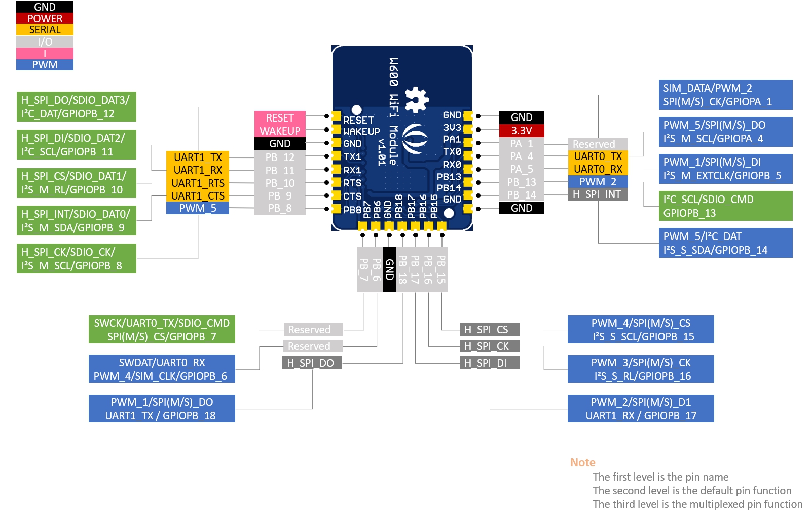
Hardware Interface Type UART/SPI/GPIO
Interface rate 2Mbps@UART (Max)
50Mbps@SPI (Max)
Operating Voltage 3.3V(Module)/5V(Development Board)
Operating humidity 5%~90% (No condensation)
Operating temperature 0 ~ +50℃
Software Network Type STA/AP/AP+STA/Wi-Fi Direct
Verification WEP/WPA-PSK/WPA2-PSK
Encryption WEP64/WEP128/TKIP/CCMP(AES)
WPS Function WPS
Energy saving PS-POLL/Standby
Network protocol TCP/UDP/ARP/ICMP/DHCP/DNS/HTTP
Interface Protocol AT+ instruction set
For more detail about specifications, please check the W600 Specification V1.0.0_EN.pdf and W600
HardwareDesignGuide_v1.0.1.pdf

4 / 17
Typical Applications
intelligent home appliances
smart home
wireless audio and video
smart toys
medical monitoring
industrial control
other Internet of Things applications

7 / 17
Getting Started
To use the W600 Module, you need to use USB-to-Serial Tools to connect the RX/TX pins to your computer,
also you need to power this module with the 3.3v and GND pins.
!!!Note For mac, we found that some version of mac system can not recognize the on-board USB-to-Serial
chip CH330N, please check here for solution Mac os driver issue
We use the serial port tool sscom to send the AT command. You can use your favorite serial port tool, in case
you want to use sscom, you can download it Here.
What ever, please make sure you have checked the option AddCrLf, and set the baud rate to 115200
Tap AT+ then click SEND or press ++enter++ key to to check if the connection was successfully established.
AT+
When it returns +OK, you can use the AT command to control this module.
Create a SoftAP process
1- WPRT sets the wireless network card working mode to SoftAP:
AT+WPRT=2

8 / 17
2- APSSID Set the AP SSID for the STA, e.g.MyAP:
AT+APSSID=MyAp
3- APENCRY Set the wireless network card security mode to WEP64:
AT+APENCRY=1
Parameter:
open:0,WEP64:1,WEP128:2
4- APKEY Set the wireless network card key to 12345
AT+APKEY=1,1,12345
Parameter 1:Key format, 0 means HEX, 1 means ASCII
Parameter 2:index: Key index number, 1 to 4 are used for WEP encryption keys, and other encryption
methods are fixed to 0.
Parameter 3:wireless key, e.g.:12345
5- APNIP Set the ip address and subnet mask
AT+APNIP=1,192.168.1.1,255.255.255.0,192.168.1.1,192.168.1.1
Parameter 1:address type: 0 means dynamic allocation using DHCP, 1 means static address
parameter 2:ip:192.168.1.1
parameter 3:netmask:255.255.255.0
parameter 4:gateway:192.168.1.1
parameter 5:dns:192.168.1.1
6- PMTF saves the above parameters to spi flash, just start from step 7 with the next boot.
AT+PMTF
7- WJOIN Create wireless network MyAp
AT+WJOIN

9 / 17
8- SLIST Query the STA information which connected to your SoftAP.
AT+SLIST
Scan AP Process
Wireless network card scanning AP's AT command is :
AT+WSCAN
The last paremeter is the signal strength, unit db
STA joins the AP process
1- WPRT Set the working mode to STA
AT+WPRT=0
2- SSID Set the AP name to join. e.g. TEST_AP

10 / 17
AT+SSID=TEST_AP
3- KEY Set the wireless key of the AP you want to join. e.g. 12345678
AT+KEY=1,0,12345678
parameter 1:0 means HEX, 1 means ASCII
parameter 2:index: The key index number, 1 to 4 is used for the WEP encryption key. The other encryption
methods are fixed to 0.
parameter 3: Wireless key e.g.:12345678
4- NIP Enable DHCP
AT+NIP=0
5- PMTF Save the above parameters to spi flash, Just start from step 6 with the next boot
AT+PMTF
6- WJOIN Join the wireless network TEST_AP
AT+WJOIN

11 / 17
Create an APSTA process
1- WPRT Set the working mode to APSTA
AT+WPRT=3
2- SSID Set the AP name to be joined, such as TEST_AP
AT+SSID=TEST_AP
3- KEY Set the wireless key of the AP you want to join. e.g. 12345678
AT+KEY=1,0,12345678
parameter 1:0 means HEX, 1 means ASCII
parameter 2:index: The key index number, 1 to 4 is used for the WEP encryption key. The other encryption
methods are fixed to 0.
parameter 3: Wireless key e.g.:12345678
4- APSSID Set the network name of the created SOFTAP

12 / 17
AT+APSSID=”MYSoftAP”
5- APENCRY Set the encryption type of SoftAP (such as WPA2-TKIP)
AT+APENCRY=5
6- APKEY Set the password for SoftAP (e.g. ASCII code 87654321)
AT+APKEY=1,0,87654321
7- APNIP Set the IP address and subnet mask
AT+APNIP=1,192.168.1.1,255.255.255.0,192.168.1.1,192.168.1.1
8- PMTF Save the above parameters to spi flash, just start from step 9
AT+PMTF
9- WJOIN Join the wireless network TEST_AP
AT+WJOIN
!!!Note For more detail about AT command, please check the WM_W60X_SDK_AT Command_V1.0.2.pdf
Firmware Programming
For the firmware programming please check here:
WM_W60X_SDK_User Manual_V1.0.0.pdf and WM_W60X_Firmware Generation Guide_V1.1.pdf
FAQ
Q1.How the STA disconnects the AP
A: The wireless network card disconnects the AP's AT command:
AT+WLEAV
Q2.SoftAP disconnected

13 / 17
A: The AT command of SoftAP disconnected network is:
AT+WLEAV=2
Q3.How STA view current status
A: The AT command for the wireless network card to view the status of the current network card is:
AT+LKSTT
Q4. How to View current SoftAP status
A: The AT command to view the current SoftAP status is:
AT+APLKSTT

15 / 17
INTEGRATION INSTRUCTIONS
1.0
This modular transmitter complies with FCC Rules Part 15C.
1.1 Specific operational use conditions Antenna Change Notice to Host manufacturer
Recommend using antenna which certified with this module mentioned in this manual. If you desire to
increase antenna gain and either change antenna type or use same antenna type certified, a Class II
permissive change application is required to be filed by us, or you (host manufacturer) can take responsibility
through the change in FCC ID (new application) procedure followed by a Class II permissive change
application, based on the new emissions testing. Please perform testing on frequency bands where the
antenna gain is highest, worst-case band-edges based on original filing, and only on frequency bands where
the antenna gain is highest.
1.2 RF exposure compliance instruction
This module is limited to installation in mobile application with a minimum separation distance of at least 20
cm from a person’s body, a separate approval is required for all other operating configurations, including
portable configurations with respect to §2.1093 and different antenna configurations. Host product
manufacturer shall at least provide information of minimum separation distance to end users in RF exposure
compliance statement to end users in their end-product manuals.
1.3 This module is tested with the following antenna
Antenna Type Brand/ manufacturer Model No. Max. Antenna Gain
PCB Seeedstudio 113990614 0.88dB
1.4 Labelling and compliance statement instruction for host product manufacturer
Please notice that if the FCC identification number is not visible when the module is installed inside another
device, then the outside of the device into which the module is installed must also display a label referring to
the enclosed module. This exterior label can use wording such as the following: “Contains FCC ID: Z4T-
W600MODULE” any similar wording that expresses the same meaning may be used.
§ 15.19 Labelling requirements shall be complied on end user device. Labelling rules for special device, please
refer to §2.925, § 15.19 (a)(5) and relevant KDB publications. For E-label, please refer to §2.935.
1.5 Guide on test modes and additional testing requirements
Host product manufacturer is ultimately responsible for testing their end-product for any additional
compliance requirements required with this module installed (for example, digital device emissions, PC
peripheral requirements, additional transmitter(s) in the host, etc.).
Furthermore, FCC KDB 996369 D04 Module Integration Guide v01 has elaborated guidance for modular
transmitter integration for host product manufacturers.

16 / 17
Test software access to different test modes:
RF Test Software: NCAUTH_V1.1.05
RF Test Mode: RF out at 802.11b/g/n20/n40, RF receive at 802.11b/g/n20/n40, AP model, Station model
1.6 Disclaimer on additional testing, Part 15 Subpart B compliance of Host Product
This modular transmitter is only FCC authorized for the specific rule parts listed on our grant, host product
manufacturer is responsible for compliance to any other FCC rules that apply to the host not covered by the
modular transmitter grant of certification.
Host manufacturer in any case shall ensure host product which is installed and operating with the module is in
compliant with Part 15B requirements.
Please note that For a Class B or Class A digital device or peripheral, the instructions furnished the user
manual of the end-user product shall include statement set out in §15.105 Information to the user or such
similar statement and place it in a prominent location in the text of host product manual. Original texts from
FCC Rules are as following you may refer to:
For Class B
Note
This equipment has been tested and found to comply with the limits for a Class B digital device,
pursuant to part 15 of the FCC Rules. These limits are designed to provide reasonable protection
against harmful interference in a residential installation. This equipment generates, uses and can
radiate radio frequency energy and, if not installed and used in accordance with the instructions, may
cause harmful interference to radio communications. However, there is no guarantee that
interference will not occur in a particular installation. If this equipment does cause harmful
interference to radio or television reception, which can be determined by turning the equipment off
and on, the user is encouraged to try to correct the interference by one or more of the following
measures:
Reorient or relocate the receiving antenna.
Increase the separation between the equipment and receiver.
Connect the equipment into an outlet on a circuit different from that to which the receiver is
connected.
Consult the dealer or an experienced radio/TV technician for help.
For Class A
Note
This equipment has been tested and found to comply with the limits for a Class A digital device,
pursuant to part 15 of the FCC Rules. These limits are designed to provide reasonable protection
against harmful interference when the equipment is operated in a commercial environment. This
equipment generates, uses, and can radiate radio frequency energy and, if not installed and used in
accordance with the instruction manual, may cause harmful interference to radio communications.
Operation of this equipment in a residential area is likely to cause harmful interference in which case
the user will be required to correct the interference at his own expense.

17 / 17
FCC regulatory compliance statement
§15.19 Statement
This device complies with Part 15 of the FCC Rules. Operation is subject to the following two conditions: (1)
this device may not cause harmful interference, and (2) this device must accept any interference received,
including interference that may cause undesired operation.
§15.21 Information to user
Warning: changes or modifications not expressly approved by the party responsible for compliance could void
the user’s authority to operate the equipment.
RF Exposure compliance statement
This module complies with FCC radiation exposure limits set forth for an uncontrolled environment. This
equipment should be installed and operated with a minimum distance of 20cm between the radiator and your
body. This transmitter must not be co-located or operating in conjunction with any other antenna or
transmitter.
Table of contents
Popular Wireless Module manuals by other brands

Ebyte
Ebyte E49-400T20S user manual

Telit Wireless Solutions
Telit Wireless Solutions UC864-G Hardware user's guide

ICT
ICT PRT-IVO-IF installation manual

Cellvision Systems
Cellvision Systems GLM-100 user manual

Telit Wireless Solutions
Telit Wireless Solutions WE310F5-I Hardware user's guide

ESD
ESD CAN-CBX-COM2 manual