HANSONG HSBT3031-08 User manual

Bluetooth Module
HSBT3031-08
User Manual
HANSONG (NANJING) TECHNOLOGY CO. , LTD.
APROVED MANAGER CHECKED FILLED
Customer.
S.MANAGER MANAGER CHECKED CHIEF FILLED

HSBT3031-08 module_datasheet Version2.0– Jun. 15th
HANSONG ( NANJING) TECHNOLOGY CO.,LTD
2
Revision control
Revision Date/Author Check by Approve by Remarks
V1.0 Bruce/25.11.2021 Initial
V2.0 Bruce/15.02.2022 Optimize FCC ISED Statement

HSBT3031-08 module_datasheet Version2.0– Jun. 15th
HANSONG ( NANJING) TECHNOLOGY CO.,LTD
3
Contents
1Overview............................................................................................................................ 5
2Features............................................................................................................................. 5
3Applications ....................................................................................................................... 6
4Specifications..................................................................................................................... 6
5Pin view ............................................................................................................................. 7
6Pin Assignment .................................................................................................................. 8
7Interfaces......................................................................................................................... 11
7.1 USB Interface............................................................................................................ 11
7.1.1 USB device port .............................................................................................. 11
7.1.2 USB charger detection.................................................................................... 12
7.2 PIO ............................................................................................................................ 12
7.2.1 PIO pad allocation............................................................................................. 12
7.2.2 Standard I/O ..................................................................................................... 12
7.3 Transaction bridge.................................................................................................... 13
7.4 RESET# reset............................................................................................................. 14
7.5 SYS_CTRL .................................................................................................................. 14
7.6 LED Drivers ............................................................................................................... 15
7.6.1 LED pads ........................................................................................................... 15
7.6.2 LED controllers.................................................................................................. 15
7.7 Audio interfaces ....................................................................................................... 16
8Battery Charger ............................................................................................................... 17
9Power supply ................................................................................................................... 20
10 General Specifications..................................................................................................... 22
10.1 Absolute Maximum Ratings: .................................................................................... 22
10.2 Recommended Operating Condition: ...................................................................... 22
10.3 Battery Charger ........................................................................................................ 23
10.4 10‑bit auxiliary ADC ................................................................................................. 25
10.5 Digital terminals ....................................................................................................... 25
10.6 LED Driver Pads ........................................................................................................ 26
11 Layout Notes.................................................................................................................... 27

HSBT3031-08 module_datasheet Version2.0– Jun. 15th
HANSONG ( NANJING) TECHNOLOGY CO.,LTD
4
12 Module Dimension .......................................................................................................... 28
13 Reflow temperature ........................................................................................................ 29
14 FCC ISED Statement......................................................................................................... 30

HSBT3031-08 module_datasheet Version2.0– Jun. 15th
HANSONG ( NANJING) TECHNOLOGY CO.,LTD
5
1 Overview
HSBT3031-08 Bluetooth module is an intelligent wireless audio data dual-mode
transmission product independently developed by the company, which is high-end and
efficient stereo wireless transmission scheme, the module adopts QCC30xx series chips
to provide the module with high quality sound quality and compatibility better
performance.
The HSBT3031-08 Bluetooth module adopts the drive free mode. Customers only need to
connect the module to the application product, and it can be fast realize the wireless
transmission of music and enjoy the fun of wireless music.
2 Features
Main Chipset : QCC-3031-0-80PQFN-TR-00-0
Fully qualified single-chip dual-mode Bluetooth v5.1 system
High-performance programmable Bluetooth® stereo audio
SoC with Qualcomm® aptX™audio
Tri-core processor architecture with low power for
extended battery life
120 MHz Qualcomm® Kalimba™audio DSP
32 MHz Developer Processor for applications
Firmware Processor for system
Flexible QSPI flash programmable platform
Advanced audio algorithms
High-performance 24‑bit stereo audio interface
Digital and analog microphone interfaces
Flexible PIO controller and LED pins with PWM support
1-mic Qualcomm® cVc™speaker noise reduction and echo
cancellation technology
aptX, aptX HD, aptX Low Latency, SBC, and AAC audio codecs support
Serial interfaces: UART, Bit Serializer (I²C/SPI), USB 2.0
Integrated PMU: Dual SMPS for system/digital circuits, Integrated Li-ion battery charger
Size :34.1mm x 18.7mm x 3.0mm

HSBT3031-08 module_datasheet Version2.0– Jun. 15th
HANSONG ( NANJING) TECHNOLOGY CO.,LTD
6
3 Applications
Stereo Wireless Headsets.
Wired stereo headsets and headphones.
Portable stereo speakers.
Home Audio System.
4 Specifications
Model HSBT3031-08-08
Bluetooth specifications Fully qualified single-chip dual-mode Bluetooth v5.1system
Modulation mode GFSK, π / 4 DQPSK, 8DPSK
Supply voltage 3.3-5.0V
Support Bluetooth protocol A2DP V1.3.1, AVRCP v1.6, HFP V1.7, HSP v1.2
SPP v1.2,DID v1.3,HOGP v1.0,PXP v1.0.1
FMP v1.0
,
BAS v1.0
Working current
≤
20mA
Standby current
< 500uA
Temperature range
- 40 ° C to + 85 ° C
Wireless transmission range more than 10m
Transmission power support class 1 / class 2 / class 3 with maximum adjustable
10dbm
Sensitivity
- 80 DBM < 0.1% BER
Frequency range 2.402GHz-2.480GHz
External interface PIO, SPI, AIO, UART, USB, I2S, MIC, Lin, SPK (L / R)
Support system Android, IOS and windows
Audio decoding output aptX, aptX HD, aptX Low Latency, SBC, and AAC
Audio SNR ≥75dB
Distortion
≤
0.1%
FCC ID
XCO-QCC3031
ISED
7756A-QCC3031
Module size
34.1mm x 18.7mm x 3.0mm

HSBT3031-08 module_datasheet Version2.0– Jun. 15th
HANSONG ( NANJING) TECHNOLOGY CO.,LTD
7
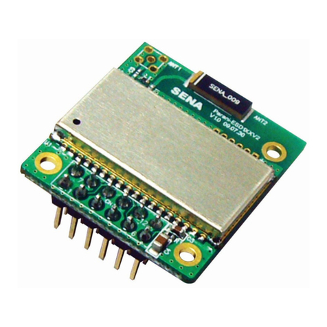
5 Pin view

HSBT3031-08 module_datasheet Version2.0– Jun. 15th
HANSONG ( NANJING) TECHNOLOGY CO.,LTD
8
6 Pin Assignment
Pin No. Pin Name Pin Type Description
1 GND GND Common Ground
2 LED5/AIO5 Analog or digital
input/ open drain
output.
General-purpose analog/digital
input or open drain LED output.
3
GND
GND
Common Ground
4
TBR_MISO_0
Digital: Bidirectional
with programmable
strength internal
pullup/pull-down
Programmable I/O line 7.
Alternative function:
TBR_MISO[0]
5
MCLK_OUT
Digital: Bidirectional
with programmable
strength internal
pullup/pull-down
Programmable I/O line 15.
Alternative function:
MCLK_OUT
6
TBR_MOSI_0
Digital: Bidirectional
with programmable
strength internal
pullup/pull-down
Programmable I/O line 6.
Alternative function:
TBR_MOSI[0]
7 TBR_CLK Digital: Bidirectional
with programmable
strength internal
pullup/pull-down
Programmable I/O line 8.
Alternative function:
TBR_CLK
8 RSTB Digital: Bidirectional
with programmable
strength internal
pullup/pull-down
Automatically defaults to RESET#
mode when the device is
unpowered, or in off modes.
Reconfigurable as a
PIO after
boot. Alternative function:
Programmable I/O line 1
9 TBR_MISO_1 Digital: Bidirectional
with programmable
strength internal
pullup/pull-down
Programmable I/O line 5.
Alternative function:
TBR_MISO[1]
10 TBR_MISO_3 Digital: Bidirectional
with programmable
strength internal
pullup/pull-down
Programmable I/O line 2.
Alternative function:
TBR_MISO[3]
11 LED2/AIO2 Analog or digital
input/
open drain
output.
General-purpose analog/digital
input or open drain LED output.
12
LED1/AIO1
Analog or digital
General-purpose analog/digital

HSBT3031-08 module_datasheet Version2.0– Jun. 15th
HANSONG ( NANJING) TECHNOLOGY CO.,LTD
9
input/
open drain
output.
input or open drain LED output.
13
LED0/AIO0
Analog or digital
input/ ope
n drain
output.
General-purpose analog/digital
input or open drain LED output.
14 SYS_CTRL Digital input
Typically connected to an
ON/OFF
push button. Boots
device in
response to a button
press when power is still present
from battery
and/or charger but
software has placed the device in
the OFF or
DORMANT state.
Additionally useable as a digital
input in normal operation.
No pull.
Additional function:
PIO[0] input only
15
VBAT
Supply
Battery voltage input.
16 GND GND Common Ground
17 VDD_IO Supply 1.8 V/3.3 V PIO supply.
18 1V8_SMPS Power out 1V8_SMPS out.
19 GND GND Common Ground
20 VCHG Supply Supply to SMPS power switch
from charger input.
21 CHG_EXT Analog External charger transistor current
control. Connect to base of
external charger transistor as per
application schematic.
22
VBAT_SENSE
Analog
Battery voltage sense input.
23 3V3_LDO Power out Bypass regulator decoupling.
24 USB_N Digital USB Full Speed device D- I/O.
25 USB_P Digital USB Full Speed device D+ I/O.
26 GND GND Common Ground
27 GND GND Common Ground
28 PCM_SYNC Digital: Bidirectional
with programmable
strength internal
pullup/pull-down
Programmable I/O line 17.
Alternative function:
PCM_SYNC
29 PCM_CLK Digital: Bidirectional
with programmable
strength internal
pullup/pull-down
Programmable I/O line 16.
Alternative function:
PCM_CLK
30 PIO_22 Digital: Bidirectional Programmable I/O line 22.

HSBT3031-08 module_datasheet Version2.0– Jun. 15th
HANSONG ( NANJING) TECHNOLOGY CO.,LTD
10
with programmable
strength internal
pullup/pull-down
Alternative function:
UART_RX
31 PIO_23 Digital: Bidirectional
with programmable
strength internal
pullup/pull-down
Programmable I/O line 23.
Alternative function:
UART_TX
32 PCM_DIN_0 Digital: Bidirectional
with programmable
strength internal
pullup/pull-down
Programmable I/O line 19.
Alternative function:
PCM_DIN[0]
33 PCM_DOUT_0 Digital: Bidirectional
with programmable
strength internal
pullup/pull-down
Programmable I/O line 18.
Alternative function:
PCM_DOUT[0]
34 PCM_DOUT_1 Digital: Bidirectional
with programmable
strength internal
pullup/pull-down
Programmable I/O line 20.
Alternative function:
PCM_DOUT[1]
35 PCM_DOUT_2 Digital: Bidirectional
with programmable
strength internal
pullup/pull-down
Programmable I/O line 21.
Alternative function:
PCM_DOUT[2]
36 MIC1_N/
LINEIN_L_N
Analog Microphone differential 1 input,
negative.
Alternative function:
Differential audio line input left,
negative
37 MIC1_P/
LINEIN_L_P
Analog Microphone differential 1 input,
positive.
Alternative function:
Differential audio line input left,
positive
38
MIC_BIAS
Analog
Mic bias output.
39 MIC2_N/
LINEIN_R_N
Analog Microphone differential 2 input,
negative.
Alternative function:
Differential audio line input right,
negative
40
MIC2_P/
LINEIN_R_P
Analog
Microphone differential 2 input,
positive.
Alternative function:
Differential audio line input right,

HSBT3031-08 module_datasheet Version2.0– Jun. 15th
HANSONG ( NANJING) TECHNOLOGY CO.,LTD
11
positive
41 HPR_N/SPKR_N Analog Headphone/speaker differential
right output, negative.
Alternative function:
Differential right line output,
negative
42
HPR_P/SPKR_P
Analog
Headphone/speaker differential
right output, positive.
Alternative function:
Differential right line output,
positive
43 HPL_N/SPKL_N Analog Headphone/speaker differential
left output, negative.
Alternative function:
Differential left line output,
negative
44
HPL_P/SPKL_P
Analog
Headphone/speaker differential
left output, positive.
Alternative function:
Differential left line output,
positive
45 GND GND Common Ground
7 Interfaces
7.1 USB Interface
HSBT3031-08 has a USB device interface: An upstream port, for connection to a host
Phone/PC or battery charging adaptor.
7.1.1 USB device port
The device port is a USB2.0 Full Speed (12 Mb/s) port. Typically HSBT3031-08 enumerates
as a compound device with a hub with the enabled audio source / sink / HID / mass storage
device appearing behind this hub.
The DP 1.5 k pull-up is integrated in HSBT3031-08. No series resistors are required on the
USB data lines.
HSBT3031-08 contains integrated ESD protection on the data lines to IEC 61000-4-2 (device
level). In normal applications, no external ESD protection is required.
Extra ESD protection is not required on VCHG (VBUS) because HSBT3031-08 meets the USB

HSBT3031-08 module_datasheet Version2.0– Jun. 15th
HANSONG ( NANJING) TECHNOLOGY CO.,LTD
12
certification requirements of a minimum of 1uF, and a maximum of 10 μF being present on
VCHG (VBUS).
The VCHG input of HSBT3031-08 is tolerant of a constant 6.5 V and transients up to 7.0 V. If
extra overvoltage protection is required, external clamping protection devices can be used.
7.1.2 USB charger detection
HSBT3031-08 supports charger detection to the USB BCv1.2 standard.
It provides Data Contact Detection (DCD) using an internal current source, and provides:
■Detection of standard downstream ports (SDP)
■Charging downstream ports (CDP)
■Dedicated downstream ports (DCP)
The voltage on the USB data lines can be read by the 10‑bit auxiliary ADC. This allows
detection of proprietary chargers that voltage bias USB the data lines.
For USB C type connectors, the LED pins can be used to detect the voltage on the CC line
pins to detect the charge current capabilities of the upstream device.
7.2 PIO
HSBT3031-08 has the following digital I/O pads:
■17 PIO pads:
Including 1 x Reset (active low) pad: PIO[1]
■4 x pads intended for LED operation: LED[5, 2:0]
■1 x Output on standard pad: XTAL_CLKOUT
■1 x Power-on signaling: SYS_CTRL, usable as an input after boot.
7.2.1 PIO pad allocation
The following HSBT3031-08 functions have specific pad allocations:
■LED pads
■Transaction bridge
■Audio I²S/PCM
NOTE Digital microphones, SPDIF, UART, Bit Serializer (I²C/SPI), and LED PWM controllers
can use any PIO.
7.2.2 Standard I/O
The standard digital I/O pins (PIO) on HSBT3031-08 are split into separate pad domains. Each
VDD_PADS domain can be separately powered, from 1.7 V to 3.6 V. When PIOs in a supply
domain are used for a high-speed interface, decoupling the respective VDD_PADS pin with a

HSBT3031-08 module_datasheet Version2.0– Jun. 15th
HANSONG ( NANJING) TECHNOLOGY CO.,LTD
13
100 nF decoupling capacitor may be beneficial. The VDD_PADS of a particular pin should be
powered before voltages are applied to any PIO powered by that domain, otherwise back
powering can occur through the electrostatic discharge (ESD) protection in the pad.
PIO can be programmed to have a pull-up or pull down with two strengths (weak and strong).
PIO can also be programmed with a sticky function where they are strongly pulled to their
current input state. PIO have a reset pull state, after reset the pulls can be re-configured by
software.
PIO also have a programmable drive strength capability of 2, 4, 8, or 12 mA.
All PIO are readable by all subsystems, but for write access are assigned by software to
particular subsystem control. PIO inputs are via Schmitt triggers.
7.3 Transaction bridge
The transaction bridge is an external bridge into the internal transaction bus between
HSBT3031-08 subsystems. It is the primary debug interface and can also be used for
production programming.
A USB to transaction bridge interface (TRBI200) is available. For details, contact a QTIL sales
representative.
The transaction bridge is multiplexed on PIO[8:2], see Table 7.3-1.
NOTE A direct USB2.0 connection from a host computer to the HSBT3031-08 can be used
for most debugging and programming activities. For more details, see ADK
documentation.
TRBI200 can use USB3.0 for maximum data rate.
NOTE USB3.0 signals can generate noise in the Bluetooth ISM band. For applications
where sensitive RF measurements take place, QTIL recommends connecting
TRBI200 using USB2.0.
The transaction bridge is a multilane interface, and only requires three wires for its
minimum configuration (suitable for production programming).
NOTE The TRBI200 USB transaction bridge interface requires power for input/output
buffers to be supplied externally. This voltage must match the power supply domain
used for the TRB pads (VDD_PADS_1).
NOTE Minimum configuration is sufficient for production programming and code download,
but not for extensive debug and code tracing. The configuration in use is
automatically detected.
Table 7.3-1 Transaction bridge PIO multiplex

HSBT3031-08 module_datasheet Version2.0– Jun. 15th
HANSONG ( NANJING) TECHNOLOGY CO.,LTD
14
Transaction bridge debug access is lockable. When locked, this interface only becomes active
after the correct unlock key sequence is provided.
7.4 RESET# reset
The HSBT3031-08 digital reset pin (RESET#) is an active low reset signal. PIO[1] defaults to
RESET# upon boot.
The pin is active low and on-chip glitch filtering avoids the need to filter out any spurious noise
that may cause unintended resets. The RESET# pin has a fixed strong pull-up to
VDD_PADS_1, and therefore can be left unconnected. The input is asynchronous, and is
pulse extended within HSBT3031-08 to ensure a full reset.
HSBT3031-08 contains internal Reset Protection functionality to automatically keep the power
rails enabled and enable the system to restart after unintended reset (such as a severe ESD
event). Assertion of RESET# beyond the Reset Protection timeout (typically greater than ~1.8
s) causes the device to power down if VCHG is not present and SYS_CTRL is low.
HSBT3031-08 then requires a SYS_CTRL assertion or VCHG attach to restart.
NOTE HSBT3031-08 is always powered if VCHG is present. It does not power down if
RESET# is asserted while VCHG remains present.
QTIL recommends that HSBT3031-08 is powered down via software-controlled
methods rather than external assertion of RESET#.
Holding RESET# low continuously is not the lowest HSBT3031-08 power state,
because pull downs are enabled on VCHG and VDD_BYP in this state.
RESET# is guaranteed to work if held low for 120us.
After boot, PIO[1] is configurable as a digital PIO.
7.5 SYS_CTRL
SYS_CTRL is an input pin that acts as a power on signal for the internal regulators. It can also
be used as an input (appears to software as virtual PIO[0]) or as a multifunction button.
From the OFF state, SYS_CTRL must be asserted for >20 ms to start power up.
SYS_CTRL is VBAT tolerant (4.8 V max), and typically connected via a button to VBAT.

HSBT3031-08 module_datasheet Version2.0– Jun. 15th
HANSONG ( NANJING) TECHNOLOGY CO.,LTD
15
SYS_CTRL has no internal pull resistor, and requires an external pull-down if left undriven.
SYS_CTRL can be logically disconnected from the power on signal for internal regulators by
software. Therefore, for example, once booted, software takes control of the internal regulators
and the state of SYS_CTRL is ignored by the regulators.
7.6 LED Drivers
7.6.1 LED pads
HSBT3031-08 contains LED pads that are configurable in four different operating modes:
1. LED Driver: This mode is designed for driving LEDs. The pad operates as an open-drain
pad, tolerable of voltages up to 7.0 V. Therefore the cathode of the LED should be connected
to the HSBT3031-08 LED pad.
Each pad is rated to sink up to 50 mA of current.
2. Digital / Button input: This mode is designed for slow input signals, typically buttons. It is
not designed for fast switching digital inputs like SPI. For these types of inputs, use the
standard PIOs.
In this mode, an internal weak pull-down can be enabled. Typically this is used for active high
button signals to
ensure that the input returns to 0 when the button is released. The pads are 7.0 V tolerant and
the logic 1 threshold is typically 1 V.
In digital input mode, the logic inputs can be read by the software as virtual PIO[71, 68:66].
3. Analog input: In this mode, the LED pad is used as an analog input port. The pad voltage
is routable to a 10‑bit auxiliary ADC.
4. Disabled: This is the default state for LED pads, where the pad is 7.0 V tolerant and a high
impedance with no pull-down.
NOTE LED[1] pin will be driven to ground level for up to 6 ms within 50 ms of the chip
powering up from off state or after chip reset being released.
Other LED pins might be driven to ground level for up to 300us within 50 ms of the
chip powering up from off state.
7.6.2 LED controllers
HSBT3031-08 has six PWM-based LED controllers controlled by the Applications subsystem.
Use them for driving either the LED pads (through virtual PIOs) or other available PIOs.
An application may configure the LED flash rate and ramp time using a dedicated API.
Once configured, the LED flash and ramp rate are fully hardware controlled within the
LED/PWM module. It is possible to synchronize any number of the LED drivers together. Use
the flash/ramp rate configuration to generate color change sequences on RGB LEDs.
LED outputs are able to operate in Deep Sleep state, but not in Dormant state.

HSBT3031-08 module_datasheet Version2.0– Jun. 15th
HANSONG ( NANJING) TECHNOLOGY CO.,LTD
16
7.7 Audio interfaces
■24‑bit I²S interface with 1 input and 3 output channels
■Programmable audio master clock (MCLK).
■Sony/Philips digital interface (SPDIF): 2, configurable as input or output
■Stereo analog Class-AB headphone outputs:
□Class-AB signal-to-noise ratio (SNR): ≥75dB.
□Class-AB total harmonic distortion plus noise (THD +N): ≤0.1%.
■Dual analog inputs configurable as single ended line inputs or, unbalanced or balanced
analog microphone inputs:
□SNR single-ended: ≥75dB.
□THD+N single-ended: ≥75dB.
■1 microphone bias (single bias shared by the two channels).
□Crosstalk attenuation between two inputs using recommended application circuit: ≥
75dB.
■Digital microphone inputs with capability to interface up to 6 digital microphones.
■Both analog-to-digital converter (ADC)s and digital-toanalog converter (DAC)s support
sample rates of 8, 16, 32, 44.1, 48, 96 kHz. DACs also support 192 kHz.

HSBT3031-08 module_datasheet Version2.0– Jun. 15th
HANSONG ( NANJING) TECHNOLOGY CO.,LTD
17
8 Battery Charger
The HSBT3031-08 Li-ion charger is designed to support small to large batteries (several Amp
hours). It is connectable in one of two modes:
■Internal configuration: Supporting charge rates of 2 mA to 200 mA with no external
components required.
■External configuration: Supporting charge rates of 200 mA to 1800 mA with the addition of
one PNP pass device and external resistor.
The charger system has five main operating states. The current charger status can be read by
application software.
Figure 8-1 shows the five states in the charge cycle.

HSBT3031-08 module_datasheet Version2.0– Jun. 15th
HANSONG ( NANJING) TECHNOLOGY CO.,LTD
18
Figure 8-1 Charge cycle states
Trickle charge
This mode is entered when VBAT is sensed in the range 0 to Vpre. This is encountered only
with a deeply discharged battery (below Vpre threshold, point (A)), or when the cell's battery
protection circuit has opened, temporarily disconnecting the cell. It is used to pass a small
charging current to safely charge a cell, and also cause a cell battery protection circuit to reset.
The hysteresis on Trickle charge into Pre-Charge is typically 100 mV.
During Trickle charge, HSBT3031-08 controls charge current internally. The external pass
transistor is not used.
Parameters in Trickle charge
Pre-charge
This mode is entered when VBAT is sensed in the range Vpre to Vfast. In this range, it is not
recommended to charge the cell at maximum rate, but a faster charge rate than that of Trickle
charge is allowable. Typically this is ~10 % to 20 % of the Fast charge rate. The Vfast
threshold, point (B) is programmable.
The hysteresis on the Vfast transition from Pre-Charge to Fast charge is typically 200 mV.
During Pre-Charge, HSBT3031-08 controls the charge current internally and the external pass
transistor is not used.
Parameters in Pre-charge

HSBT3031-08 module_datasheet Version2.0– Jun. 15th
HANSONG ( NANJING) TECHNOLOGY CO.,LTD
19
Fast charge
Fast charge has two parts:
■Constant current: Entered when VBAT is sensed in the range Vfast to Vfloat point (C). This
is the maximum charge rate, and should be set according to the battery manufacturers Data
Sheet.
■Constant voltage: When Vfloat is reached the cell voltage is maintained at Vfloat, and the
current slowly reduces until the termination point (E) is reached where charging ceases, and
the charger transitions to Standby mode.
Vfloat can be configured from 3.65 V to 4.40 V in 50 mV increments. This allows use of cells
with different Vfloat values, or cell life extension by reducing Vfloat. Vfloat can also be altered
depending on temperature change, for cell life protection.
The current termination point (E) can be adversely influenced by dynamic changes in VBAT
load current, or to a lesser extent changes in VCHG voltage.
Parameters in Fast charge
Standby mode
Once the charge current has fallen and the charger is terminated, the system enters Standby
mode. In Standby mode, the charger does not charge. It continues to monitor the battery
voltage. If the voltage falls back below Vfloat
by more than a configurable threshold Vhyst, point (D), then the charger re-enters Fast charge
mode. Vhyst is expressed as a percentage of Vfloat.
In this way, the charger system maintains the cell near full charge while prolonging cell life.
Parameters in Standby mode

HSBT3031-08 module_datasheet Version2.0– Jun. 15th
HANSONG ( NANJING) TECHNOLOGY CO.,LTD
20
9 Power supply
The system have three power supply mode:
Mode1: Single 3.3V only supply (3.3V I/O)
For improving the noise, recommend adding one 10Uf capacitor on the power supply
pin
Mode2. VBAT only supply (1.8V I/O).
For improving the noise, recommend adding one 10Uf capacitor on the power supply pin
Table of contents
