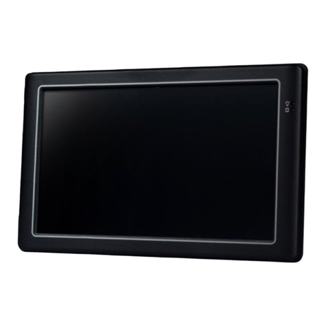
SeeEyes SC-IPM07HD User manual

7 inch wide touch screen
Versatile IP Test Monitor
This product is for CCTV system installation and management. Some problems may occur with
inappropriate use.
Video Surveillance Products (Installation and management)
Please read the instructions prior to its use and keep it with the warranty certificate.
Release Version 1.8

2
Cautions for use of this product
If you give excessive shock to this product or drop it, LCD may be damaged. Therefore, have a special care
not to break it. (The damaged LCD is not available for free A/S even in warranty.)
Do not spray water directly and wipe this product gently with a dry towel when you clean it. Have a
special care for LCD shock during cleaning.
When using outdoors, be careful to prevent water or other foreign objects from entering this product.
(It may cause fire or malfunction of the product. In this case, free A/S is not available even in warranty.)
Do not apply power to video input connectors.
Do not install the product in the following places: extremely low or high temperature conditions; places
exposed to rain, snow, or high humidity; places containing or exposed to oil and gas; places exposed
to vibration and shock; places under direct sunlight or exposed to outdoor weather conditions; places
exposed to radio waves (RF) or near to power lines (for EX-SDI, HD-SDI). It may cause low performance or
malfunction of the unit.
Use exclusive adapter only for recharging the built-in batteries. Otherwise, it may cause fire or explosion.
(When the red LED of the adapter is flickering during recharging, please contact where you purchased
this product)
The warranty for the built-in batteries is for 6 months from the purchase date.
LI-Polymer Batteries (11.1v / 5,680mAh) are built in this product. Do not disassemble or short-circuit the
batteries. (Free A/S is not available in this case)
If the charger terminal is short-circuited or has the polarity in opposite way, the batteries may be
damaged.
Keep this product in the provided bag to prevent the main body and LCD from getting cracked.
Do not put any conductive materials such as screwdrivers, coins, metal parts, etc.
Do not place this product to where water is falling or splashing and where has water inside such as flower
vases.
Stop using this product immediately and contact where you purchased this product when any smoke or
smell is produced.
Do not disassemble this product on your own and contact where you purchase this product when it does
not work properly. (You do not have free A/S for any failure caused by your own decomposition)
When this product is left for a long time and discharged, connect to WI-FI. When WI-FI is connected, the
time is set automatically.
When Micro SD Card is bent or cracked, it may cause some problems.
When the life of Micro SD Card comes to an end, the video storage and playback are not available.
Reset it to factory defaults if the product is paused frequently or does not work properly.
Press and hold the power button for about 7 seconds to shut down this product forcibly when it is paused
during use or the touch pad or D-pad does not work properly. After then, please turn it on again for use.
Press and hold the power button for about 7 seconds to shut down this product forcibly when it is paused
during use or just after resetting to factory defaults. After then, please turn it on again for use

3
Cautions for use of the memory card
Checklist for the memory card selection
Micro SD/SDHC/SDXC memory cards are compatible with this test monitor.
Compatibility between memory cards and this test monitor depends on the brand and type of memory cards.
Memory cards from the following brands are recommended for use with this test monitor.
Micro SD/SDHD/SDXC Memory Card: Sandisk, Transcend, Samsung
The recommended capacity of Micro SD card is 4GB~64GB.
When the frame rate is 30fps or lower in saving video, a memory card of class 6 or higher is recommended.
When the frame rate is 31fps or higher, a memory card of class 10 or UHS-1 is recommended.
Memory card type and capacity
Type Capacity
Micro SD Card 2GB Memory Card
Micro SDHC Card 4~32GB Memory Card
Micro SDXC Card 64GB Memory Card
Please check the memory card logo on the label of the memory card.
Memory Card Classes
You can find a number marked in a circle on the memory card. It is called 'Class'.
Type Capacity
Class 2 The class 2 can transmit 2MB per second and is not appropriate for video and/or
voice storage.
Class 4 The class 4 can transmit 4MB per second and is not appropriate for video and/or
voice storage.
Class 6 The class 6 can transmit 6MB per second and is appropriate for low- quality video
and/or voice storage.
Class 10 The class 10 can transmit 10MB per second and is appropriate for high- quality
video and/or voice storage.
Class UHS The class UHS can transmit 50MB per second and is appropriate for high- quality
video and/or voice storage.
The classes of memory cards indicate the transmission speed per second and a high-class memory card is
required for high quality video transmission.
Android supports the FAT32 method only. A SD memory card must be formatted prior to its use, and a
separate program is required to use a memory card with 64GB or higher capacity as it is unavailable to format
it in FAT32 method in the window.

4
Cautions for use of the memory card
Removal of the memory card
Errors may occur in the saved file if you remove the memory card during use.
Please refer to the following instructions to remove the memory card.
1Enter My Apps page from the Home screen.
Main Home
2Select Settings.
3Click Storage on the Settings menu.
Settings Menu

5
Cautions for use of the memory card
4Check if the Unmount SD card is enabled in the storage page.
Storage Screen
Recheck the inserted SD card status if the Unmount SD card is disabled even though the SD
card is inserted. Please remove the SD card and insert it again.
5Select OK when a message for unmounting the SD card is shown on the screen.
Unmount Screen
If the SD card unmount is still enabled even after selecting OK button, please reboot this test
monitor and try the steps above again.
For SD card insertion, no settings are required.

6
Overview
Table of Contents
Overview
Product Parts and Descriptions
Cautions for use of this product
Cautions for use of the memory card
Table of contents
3
6
2
Introduction & Features8
IP App. functions
9
NetWork
Viewer App. functions
10
Top interface
12
Front interface
Bottom Navigation and Tool Bar
13
14
Backside interface & Connection diagram
15
IP App. Functions
Launcher
16
IP camera connection and settings
17
IP camera connection by LAN
18
IP camera connection by a DHCP server
20
Checking items prior to the camera
discovery and connection
21
IP camera connection and settings23
Utilize configuration
25
IP App. Main page26
PoE voltage check, Menu in the IP App. main
page & Configuration rearrangement
27
IP device search
28
Camera settings29
Camera network settings
Edit media profile
Live video main page
30
Live video menu bar
31
Video recording
32
Snapshot capturing
33
Audio input & Video output codec change
34
Pan/Tilt functions
35
Zoom function
36
Presets & Video information
37
Configuration storage
38
Camera configuration context menu
39
Monitor IP settings
40
Product components
11
IP device discovery22
40
IP address selection & Link-local address
41
Ping test
42
43
44

7
Table of Contents
Overview
Viewer App. Functions
SDI / HDMI / HD Analog
Main page
Supported resolution
Signal level meter function
45
Focus meter function & CRC error count function
46
Video menu bar
47
PTZ
48
RS-485 Tx.
49
RS-485 Rx. & Analyze function
50
UTC
51
Video recording
52
Video capturing & How to use gallery
53
PoC function
54
User settings
55
App. update,USB Lan Card
56
Specifications
57
FAQ
58
Extra features
59
63
Warranty certificate
61
64

8
Overview
Features
1280 x 800 High resolution IPS 7 inch TFT-LCD panel with capacitance-type touch screen
Introduction
This IP test monitor is a multifunctional test monitor based on Android system for convenient monitoring and
maintenance for video surveillance systems.
As this tester supports ONVIF, the international standard for IP security products, it is possible to connect with
various network cameras easily and check their video. It can supply PoE (Power over Ethernet) to a PoE camera.
The test monitor is feature-rich with a variety of functions such as network camera setting change and PTZ
control. It is particularly optimized for camera installation.
In addition, you can check live video of HD/EX-SDI, Analog and HD Analog cameras, and for HD/EX-SDI, if your
camera is a PoC (Power over Coaxial) camera, this test monitor can supply power to the camera over coaxial
cable. RS-485 is supported for RS-485 data communication and then the camera PTZ and OSD menu control are
available in a remote distance.
For HD Analog (AHD/TVI/CVI) and CVBS, the camera PTZ and OSD control are available by UTC (Up the Coaxial)
function.
This test monitor has 7" IPS capacitance-type touch screen in 1280x800 resolution on the front side,
D-pad(directional keys) and other function buttons on the right side for the user's convenience. Also, optical
bonding is applied for visibility in outside work to provide the screen with clear image. This test monitor
provides the best solution to users for video surveillance camera installation and system maintenance as it is
compatible with various types of cameras (over 7,000 models of ONVIF conformant network cameras.).
LED Back light for clear image
Optical bonding applied for outdoor environment
Power supply to camera (DC12V/ 500mA) by using DC Jack
USB Port (2.0) with 5V power out
Micro SD card port for internal capacity expansion (Card is optional)
Dual speaker for sound play
Sleep mode to save the battery(automatically power off after 10 minutes in its sleep mode)
5,680mAH Li-polymer battery
Exclusive charger for this test monitor (In-vehicle charger is optional)
Portable bag with the strap for hands-free use and convenient installation
Rubber handle cover on both sides of this tester for prevention of slipperiness
Guard cover to protect BNC connectors
Test monitor stand for convenient monitoring
LED indicators for D-pad(directional keys) and other function buttons
Miracast function for synchronization of this test monitor with an external device

9
IP App. functions
IP camera settings
IP camera video preview and IP camera address setting change available when building IP systems.
Support various transport protocols
Support HTTP, TCP and UDP.
Video recording and snapshot
Video recording and snapshot for each signal and real-time playback.
PTZ function
Pan/Tilt/Zoom/Preset the connected PTZ camera.
Support multiple audio formats: AAC. G.711 μ-Law, G.711 A-law
Playback of the audio for the connected camera.
Overview
IP Camera search
Discover the IP address of your network camera connected to this test monitor or all network cameras on
your LAN by Auto Discovery function.
Support various types of devices
Camera video display available in various types such as ONVIF, RTSP, MJPEG, etc.
Auto-complete feature for camera setting information
Easy camera settings by the auto-complete feature once the camera setting information is saved.
Camera configuration storage
Save network camera configuration to the IP App. main page.
Monitor IP setting
IP address change of the test monitor
Ping test for network status check
Ping a network camera connected with this test monitor or on your LAN to check the network connection
status.
PoE Output
PoE output up to 30W for the network PoE camera operation.
Live video checking
Real-time video monitoring of your connected IP camera.
Real-time video information checking
Data/frame transmission rates, video/audio codec, required ports, RTP transmission quality
Media configuration change
Modify or delete the set profile.
Camera initialization
Reset a camera to factory defaults.
ONVIF properties explorer
View a device’s ONVIF properties extensively (Device, Media, PTZ, etc.)
Focus meter
Show the current status of the camera focus in numerical values on the screen to adjust camera focus more
easily and accurately.
PoE Voltage check
Check the voltage of the PoE supplied from an item.

10
Overview
Viewer App. functions
HD/EX/3G-SDI Input
Support HD/EX/3G-SDI Input. Please refer to page 59 for more information on the supported resolution.
Level meter (SDI / AHD / TVI / CVI / CVBS Support)
Show the current status of the input signal in numerical values on the screen. This function is especially useful
when any problem occurs in your system such as cables and it must be figured out.
Focus meter (SDI / AHD / TVI / CVI / CVBS Support)
Show the current status of the camera focus in numerical values on the screen to adjust camera focus more
easily and accurately.
PTZ /OSD Settings
Camera OSD menu setting and PTZ (Pan/Tilt/Zoom) function implementation by RS-485 communication.
RS-485 Communication
Data transmission in RS-485 Tx. mode and data analysis in RS-485 Rx. mode.
RS-485 Analysis
RS-485 data analysis in analysis mode
Video recording & Snapshot
Storage capacity extension possible by mounting Micro SD card additionally. It is available to save the recorded
video or captured image into Micro SD card.
PoC Output (Optional)
PoC output up to 10W for the PoC camera operation.
Audio playback
Playback of the recorded HDMI audio signal.
HD Analog, CVBS Input
UTC (Up The Coaxial / AHD, TVI, CVI, CVBS Support)
Camera OSD menu setting and PTZ (Pan/Tilt/Zoom) function implementation through a coaxial cable without
wiring data lines by UTC function.
CRC Error count (SDI Support)
Built-in CRC error count function to check data loss transmitted through cables.
Support AHD/TVI/CVI Input. Please refer to page 59 for more information on the supported resolution.
HDMI Input & Output
HDMI Input through HDMI cable and video output of this test monitor in 1080p 60Hz through HDMI output
port.

11
Overview
Please check if the following components are all included in your package when you receive this item.
Product Components
Item Name Description
IP Multifunctional
Test Monitor
Charge the battery prior to its use. It may be discharged at
the time of delivery.
Exclusive bag
with strap
Keep the test monitor in this bag for its storage or use.
Otherwise, the LCD and main body may be scratched.
Exclusive Charger
This charger is exclusive for this test monitor. If any other
charger is used to recharge this device, it may generate
some problems.
Power output leads Use this cable for DC12V power output from this test
monitor through DC12V IN/OUT port.
Coaxial Cable Use this cable for SDI or Analog video signal input.
Power input leads Use this cable for DC power input.
User's Manual The manual is provided in a 64-page booklet and a separate
quick guide is provided.
USB LAN Card Wi-Fi is available to use only when the USB LAN card is
mounted on this test monitor.

12
Product Parts and Descriptions
Top Interface
12
3 4 5 6 7
8910
No. Name Description
①Power Connector
The exclusive adapter included in this package is only allowed to recharge
this test monitor. DC12V power supply for camera operation is also available
through this port by using the power output lead. There are 5,680 mAH Li-
Polymer batteries built in this monitor.
②RS-485 Communication
Camera PTZ and OSD menu settings are available by RS-485 communication
function. In addition, data reception and analysis are possible in RS-485 Rx.
and Analysis modes.
③HDMI Input/Output
HDMI input up to 1080p 60Hz resolution is possible, which is received from
external devices such as NVR or DVR. HDMI output in 1080p 60Hz resolution
is also possible.
④HD-SDI(~3G) Input HD/EX/3G-SDI video input is available and it can supply PoC (Power over
Coax) to PoC camera. (PoC is optional)
⑤IP Camera Connector
(RJ-45)
This test monitor can connect a network camera directly or via a Hub/Switch.
Also, it can supply PoE to a PoE camera.
⑥NVR Connector
(RJ-45) PoE voltage test is available through this port.
⑦Video Input AHD, TVI, CVI or CVBS input is available through this port and camera PTZ
and OSD menu settings are also easily implemented by UTC function.
⑧USB Terminal
This test monitor supports USB 2.0 and supplies 5V power through this USB
port. Wi-Fi is available to use only when the USB LAN card is mounted on this
test monitor
⑨Micro SD Card Slot Standard Micro SD card can be mounted onto this test monitor and recorded
video can be saved on it. Also, it can be used for data transfer.
⑩Power Switch
You can turn on/off this test monitor by pressing this power switch for around
three seconds, or set it to sleep mode by pressing this button for a second.
The batteries can be saved due to this sleep mode function(Automatically
power off after 10 minutes in its sleep mode)

13
Product Parts and Descriptions
Front Interface
1
2
4
5
6
No. Name Description
①Touch Screen
IPS 7 inch TFT LCD panel in 1280x800 high resolution with tempered glass is
applied. In addition, optical bonding is applied for outdoor environment and
the fingerprint can be removed easily by applying the anti-fingerprint coating
to this test monitor.
②D-Pad
(Directional Keys) These keys are for adjusting directions (Up/Down/Left/Right/SET)
③Mode button This button is for opening the menu in the App. In the Viewer App., it can be
used to switch to PTZ or OSD mode.
④Home button This button is for going to the Home screen. However, in this case, the App.
running just before turning to Home screen is still ongoing.
⑤Menu button This button is for opening the menu in the Viewer App. or IP App.
⑥Back button
This button is for terminating an App. during operation or returning to the
previous page. If you terminate the App. during PoE or PoC, the power supply
will be stopped.
3

14
Product Parts and Descriptions
Bottom Navigation and Tool Bar
1 2 3 4 5 6
No. Name Description
①Back button This button is for terminating an App. during operation or returning to the
previous page.
②Home button This button is for going to the Home screen. However, in this case, the App.
running just before turning to the Home screen is still ongoing.
③Multi window Multi window is for showing the currently active Apps.
④Screen Shot Take a screen shot of the current screen.
⑤Audio Adjust the audio volume.
⑥Menu button This button is for opening the menu in Viewer App. or IP App.

15
Product Parts and Descriptions
Connection Diagram
Backside Interface
1
2
No. Name Description
①Monitor Stand Test monitor stand for convenient monitoring. Adjust the angle of this test
monitor.
②Speaker Dual speakers are mounted. Adjust volume.
HD Analog &
CVBS Camera
HD/EX-SDI
Camera
HDMI Output
Exclusive Adapter
DC 12V
Power Output
RS-485
In/Out
HDMI Input IP Camera
USB Memory
Micro SD Card
PoE HUB Input

16
Product Functions
Launcher
1
23
4 6 7
8
5
No. Name Description
①IP Camera App. This App. is for IP video. Tap the icon to open the IP App.
②SDI Camera App. This App. is for HD/EX/3G-SDI Video. Tap the icon to open the SDI Viewer
App.
③HDMI App. This App. is for HDMI Video. Tap the icon to open the HDMI Viewer App.
④AHD Camera App. This App. is for AHD Video. Tap the icon to open the AHD Viewer App.
⑤TVI Camera App. This App. is for TVI Video. Tap the icon to open the TVI Viewer App.
⑥CVI Camera App. This App. is for CVI Video. Tap the icon to open the CVI Viewer App.
⑦CVBS Camera App. This App. is for CVBS Video. Tap the icon to open the CVBS Viewer App.
⑧My Apps Show all installed Apps.
The following launcher screen will be shown once this test monitor is turned on.

17
IP App. Functions
IP Camera Connection and Settings
1Select IP Camera App. to connect a network camera.
Launcher page
2The IP Camera App. has various functions such as IP search, camera settings,
monitor settings, ping test, gallery, etc. If you connect an IP camera by LAN
directly, please go to page 18. If you connect an IP camera by DHCP, please go to
page 20.
IP App. Home page

18
IP App. Functions
IP Camera Connection by LAN
This is for connecting an IP camera to the monitor by LAN directly without a DHCP server or a router.
1) When an IP camera is set with the DHCP or default IP address
1Tap the Monitor Settings icon in the IP App. main page to see the above page.
Monitor IP Settings Page
2Select 'Advanced Configure' at the bottom of this page to open the monitor IP setting page.
'Use Ethernet' on the top of this page shall be marked all the time.
Cautions for IP address settings
If nothing is discovered with the two IP addresses
mentioned above, please reset the camera to
factory defaults and try it again.
DHCP is enabled when the monitor is connected
to a router or a server.
3Enter 169.254.1.2 in the IP Address, do not enter anything in the Mask Address, Gateway, DNS
server and press OK. Then, all of the settings will be saved.
4Move to the IP App. main page by pressing the back button or tapping the back ( ) icon at the
bottom of the screen.
Change the monitor IP address to connect an IP camera.
The cameras discovered when entering
169.254.1.2 use a link-local address.
Otherwise, please search a camera after entering
the same IP address range of the camera.

19
IP App. Functions
2) When connecting an IP camera manually (When you know the camera IP address)
1Tap the Monitor Settings icon in the IP App. main page to see the above page.
Monitor IP Settings Page
2Select 'Advanced Configure' at the bottom of this page to open the monitor IP setting page.
'Use Ethernet' on the top of this page shall be marked all the time.
Cautions for IP address settings
When connecting an IP camera manually, please
change the monitor IP address to the same
range of the camera IP address. Otherwise, the
camera will not be discovered and connected.
If the monitor and an IP camera have different
IP address ranges, the camera will not be
discovered. If you do not remember the camera
IP address, please reset it to factory defaults
and go to page 18.
DHCP is enabled when the monitor is connected
to a router or a server.
3Enter the same values in the IP Address except for the last value as the connected IP camera's
IP address.
e.g.) Camera IP Address: 192.168.2.120, Monitor IP Address: 192.168.2.33
5Move to the IP App. main page by pressing the back button or tapping the back ( ) icon at the
bottom of the screen.
4Enter 255.255.0.0 in the Mask Address, enter the same values of the IP camera address in the
Gateway after changing the last value to 1, and press OK. Then, all of the settings will be saved.
e.g.) IP Address: 192.168.2.33, Gateway: 192.168.2.1

20
IP App. Functions
IP Camera Connection by a DHCP server
This is for connecting an IP camera to the monitor when a DHCP server or a router is connected and it
assigns an IP address to the camera and monitor automatically.
1Tap the Monitor Settings icon in the IP App. main page to see the above page.
Monitor IP Settings Page
2Select 'Advanced Configure' at the bottom of this page to open the monitor IP setting page.
'Use Ethernet' on the top of this page shall be marked all the time.
Cautions for IP address settings
When a DHCP server is configured, it
assigns an IP address to the monitor and an
IP camera.
When the camera IP address is set
manually, the camera will not be discovered
and connected.
This test monitor does not assign an IP
address to a camera. A DHCP server or a
router should be configured.
3Mark DHCP and press OK. Then, all of the settings will be saved.
4Move to the IP App. main page by pressing the back button or tapping the back ( ) icon at
the bottom of the screen.
Do not enter IP Address, Mask Address and
Gateway.
Table of contents
Popular Touch Panel manuals by other brands
AMX
AMX MXR-1001-SL Installation & hardware reference manual
Avalue Technology
Avalue Technology SID-21V-Z37-A1R user manual

Nexcom
Nexcom PPC-240T-HW-01 user manual
Crestron
Crestron TSW-70 Series product manual
veinview
veinview MT6103iP series Installation instruction
RS Automation
RS Automation AnyTouch V7 Plus Series operating instructions
