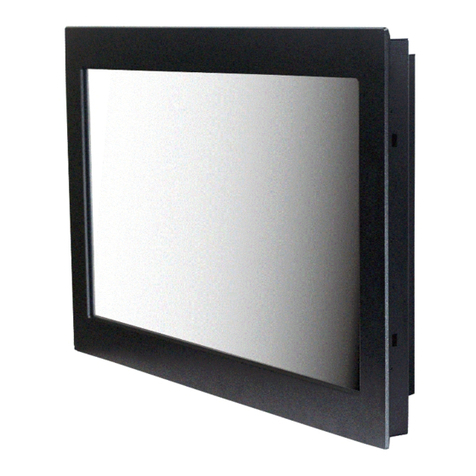
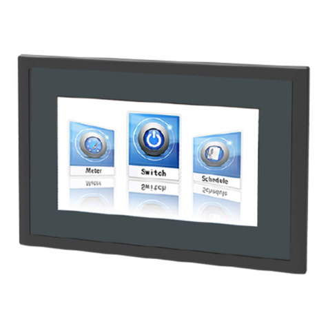
Autobase ATP12 User manual

Just Touch
autobaseTouch
Intelligent
Touch Panel
Computer
ATP12 User Manual
[Ver. 1.1]
http://www.autobase.biz

User Manual Ver.1.1

Thisuser manualandall aboutcopyright of Autobase ATP series panel computer
© 2012 Autobase, Inc. All rights reserved
Second edition, April,2013
<Notice>
Information in this documentis subject to change without priornotice.

Contents
1. ATP12 CONFIGURATION···················································5
1.1 ATP12 Hardware Specifications········································· 5
1.2 Part Names and Description·············································· 6
1.3 ATP12 Dimensions and Panel Cut-out·································7
2. SERIAL COMMUNICATION PORT ·······································8
2.1 Serial communication port················································· 8
2.1.1RS-232CPort·····································································8
3. AUTOMATED SYSTEM RECOVERY ····································9
3.1 System recovery ····························································· 9
3.1.1Initialstaterecovery·····························································9
3.1.2Restorepointupdate··························································10
4. MANUAL SYSTEM RECOVERY ········································12
4.1 Device driver setup·························································12
4.1.1Themainboardchipsetdriversetup·····································12

4.1.2Audiodriversetup······························································16
4.1.3Graphic driversetup···························································19
4.1.4Touchscreendriversetup··················································21
4.1.5Ethernet driversetup··························································24
4.2 Programs for Autobase Touch Pro Pack ·····························26
4.2.1AutobaseSCADAProgram installation································26
CUSTOMER SERVICE ························································ 27

5
1. ATP12 Configuration
1.1 ATP12 Hardware Specifications
Items
Model
ATP12
Display
12.1 inch LED Panel
SVGA (800 * 600)
CPU
Intel ATOM D525 Dual Core 1.8GHz (FSB 800MHz)
Touch Controller
Pen Mount 5-wire USB controller
Mainboard Chipset
ICH8M
Main Memory
DDR3 2GB (1066MHz/PC8500)
Secondary Storage
SSD 60GB(Max Read:500MB/s Write:400MB/s)
or HDD 500GB(SATA2 7200RPM)
VGA
Intel GMA 3150
Serial/Printer Port
RS-232C 3 Ports
USB
USB 4 Ports
Ethernet Port
Dual Gigabit Ethernet (10/100/1000Mbits/s) LAN Ports
Keyboard/ Mouse
USB Type
CD-ROM
-
OS
Windows Embedded POSReady 2009
Utility
Rescue (Recovery Tools Included)
Voltage
DC 12V(50~60Hz)
Power
38W(Max 60W)
Weight
4.02 kg
Service life of LCD Backlight
40,000h or more
<Table 1-1> AUTOBASE Touch hardware specifications

6
1.2 Part Names and Description
<Figure 1-1> Input/output ports of ATP series
Power ON/OFF : Power On/OFF switch
Audio IN/OUT : Microphone input/output ports
USB : USB 4 ports
LAN 1 : 10/100/1000 Base-T Ethernet port
LAN 2 : 10/100/1000 Base-T Ethernet port
VGA : External D-SUB VGA monitor output port
COM 1 : RS-232C input/output ports
COM 2 : RS-232C input/output ports
COM 3 : RS-232C input/output ports
COM 3 : RS-232C input/output ports
DC IN : DC-12V Power input connector

7
1.3 ATP12 Dimensions and Panel Cut-out
<Figure 1-2> ATP12 dimensions(unit : mm)
<Figure 1-3> ATP12 Panel cut-out dimensions(unit : mm)

8
2. Serial Communication port
2.1 Serial communication port
ATP12 has 3 serial ports for communication.
SerialportsCOM1/COM2/COM3 are RS-232C dedicated port so they can be used as
RS-232Conly.
2.1.1 RS-232C Port
COM1/COM2/COM3 serial ports
support the RS-232C only.
<Table 2-1> shows pin functions for
RS-232C. Before you connect device
with serialport, verify thepin
functions.
Connector Type핀Female)
Pin Number
Function
1
DCD (Data Carrier Detect)
2
RXD (Receive Data)
3
TXD (Transmit Data)
4
DTR (Data Terminal Ready)
5
GND (Ground)
6
DSR (Data Set Ready)
7
RTS (Request to Send)
8
CTS (Clear to Send)
9
RI (Ring Indicator)
<Table 2-1> RS-232C Pin Functions

9
3. Automated System Recovery
You can recover the system simply with theprevious recovery point, usingthe recovery
program, installed on Autobase Touch Panel.
3.1 System recovery
External keyboard is required when youhave to reset Autobase Touch Panel as factory state
or repairto therecent recoverypoint, forreasons such asthe damageof operating system or
lossofimportantdata.
3.1.1 Initial state recovery
During system boot, press the ' Home ' ofthe keyboard, the login dialogbox will be
appeared, asshown in <Figure3-1>.
<Figure 3-1> Login dialog box
When <Figure 3-1> login dialog box is appeared, input user(as Administrator) and
password(default password :admin) that you has set in the recoveryprogram and then the
recovery selection screen willbe displayed as shown in <figure 3-2>.

10
<Figure 3-2 Recovery selection screen
When therecoveryselection screen is
displayed,using external keyboard, select
to recover theinitial state
and select todeletethe
restored area.
3.1.2 Restore point update
When you complete thecommissioning and project in the field, you can update theoptimal
restorepoint forpreparing of problem occurrence to the system.
After bootingup Autobase TouchPanel system normally,double clickthe icon at the
bottom right corner of the screen then the logon dialog box will be appeared as shown in
<Figure3-3>
<Figure 3-3> Logon dialog box of recovery program
First of all, enter the user andpassword in <Figure 3-3> the logon dialog boxtologon.
*Factory setting –user : Administrator, Password : admin
After log on if you select ‘Restoresettings’on theleft side of dialog box, <Figure3-4>
dialog box will be appeared.

11
<Figure 3-4> Restore settings dialog box
And then if you select button, the restorepoint will be updated.
If the restorepoint is updated successfully, Restore point update complete dialogbox willbe
displayed as <Figure 3-5>.
<Figure 3-5> Restore point update complete dialog box
Generally, it isrecommended to choosethe disable restoreoption in thebottomofthedialog
box. And modify restore settings carefully. If you choose a restore mode, the system willbe
restored each time dependingonhowthe selected restore mode.For example, ifyouselect
‘Restore baseline at restart’, the restore point will be restored wheneverthe system is
restarted.

12
4. Manual System Recovery
4.1 Device driver setup
Install the device driverof Autobase Touch Panel after the Windows OS setup.
You can install devicedrivers from Touch System Software DVD or the Internet
downloading. Touch System Software DVDisincluded in theproduct package.
4.1.1 The mainboard chipset driver setup
<Figure 4-1> Mainboard chipset driver folder

13
You can find ‘infinst911autol.exe’ file as shown in <Figure 4-1> when you select
‘Driver\ATP12\Chipset’ folder from Touch SystemSoftware DVD. And run
‘infinst911autol.exe’, <Figure 4-2> initial screen will be displayed. Then select
from <figure4-2>, <Figure4-3> license agreementdialog box will bedisplayed.
<Figure 4-2> Initial screen of the mainboard chipset driver setup

14
<Figure 4-3> License Agreement dialog box of mainboard chipset driver setup
If you select from <Figure4-3>, the driver installation process will be
continued. During thedriver installation, if it needed an OS file, <Figure 4-4> screen will be
appeared andthen select theneeded file in
‘\Driver\WindowsXP_POSReady2009_SystemFiles’ folder of Touch SystemSoftware
DVD.
<Figure 4-4> Specify OS System Setup file
When theinstallation is complete, reboot systeminformation screen will be appeared as
shown in <Figure4-5> and proceed to reboot.

15
<Figure 4-5> Mainboard chipset driver installation complete screen

16
4.1.2 Audio driver setup
<Figure 4-6> Audio driver folder
You can findthe setup file in‘Driver\ATP12\Audio’ folder of Touch systemSoftware DVD.
And if you run ‘WDM_R270.exe’ from <Figure 4-6>, theinitial screen will be displayed as
shown in <Figure4-7>. Then, if you select in <Figure4-7>it willproceed to
setup. During the installation, the dialog box will be displayed to specifythe related system
file path as shown in <Figure4-8>.

17
<Figure 4-7> Audio driver setup initial screen
<Figure 4-8> Related system file location setting dialog box
Afterthe related system filelocation setting if you select button, the audio
driver installation will be completed and Windows restart setting dialog box will be
displayed as shown in <Figure 4-9>.

18
<Figure 4-9> Windows restart setting dialog box

19
4.1.3 Graphic driver setup
<Figure 4-10> Graphic driver folder
If you select theprovided Touch System software DVD ‘Driver\ATP12\Graphic’folder, the
files willbe displayed as <Figure 4-10>. And run ‘Setup.exe’in <Figure 4-10>, the graphic
driver setup initial screen willbe appeared as<Figure 4-11>.
Table of contents
Other Autobase Touch Panel manuals
