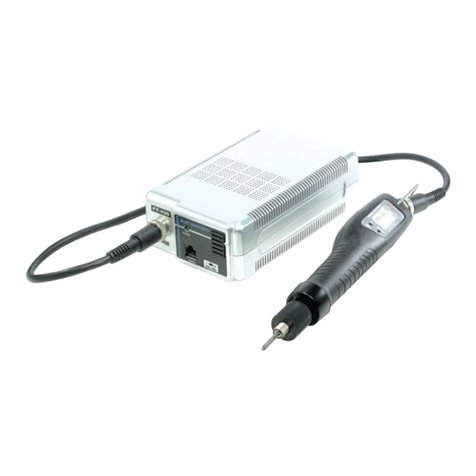
Sehan Electools YF30N User manual

2013. 06. 21
Products by CE certificate
Instruction Manual
-YF series BLDC Screwdriver -
Usage :Micro oven, Refrigerator, Washing Machine, Automobile &
home appliances assembly

- 1 -
I
NDEX
Contents Page
1. General safety rules (English) 2
2. Specific safety rules (English) 4
1. General safety rules (French) 4
2. Specific safety rules (French) 6
3. Screwdriver Set composition &features 7
4. Screwdriver
4.1 Specification 8
4.2 Available bit socket 8
4.3 Torque curve at maximum speed 8
4.4 Information by LED display 9
4.5 Dimensions 11
5. Controller
5.1 Specification 11
5.2 Overload, overheat protection 11
5.3 Dimensions 12
6. Operation
6.1 Key buttons on front panel 12
6.2 Parameter setting on front panel 14
7. In/Out interface
7.1 Ports on back panel 16
7.2 I/O interface port details 17
7.3 I/O interface diagram 17

- 2 -
1. GENERAL SAFETY RULES ENGLISH
WARNING! Read and understand all instructions. Failure to follow all instructions listed below, may
result in electric shock, fire and/or serious personal injury
SAVE THIS INSTRUCTIONS
1.1 Work Area
-Keep your work area clean and well lit. Cluttered benches and dark areas invite
accidents.
-Do not operate power tools in explosive atmospheres, such as in the presence of
flammable liquids, gases, or dust. Power tools create sparks which may ignite the
dust or fumes.
-Keep bystanders, children, and visitors away while operating apower tool.
Distractions can cause you to lose control.
1.2 Electrical Safety
-Grounded tools must be plugged into an outlet properly installed and grounded in
accordance with all codes and ordinances. Never remove the grounding prong or
modify the plug in any way. Do not use any plugs. Check with aqualified
electrician if you are in doubt as to whether the outlet is properly grounded. If the
tools should electrically malfunction or break down, grounding provides alow resistance
path to carry electricity away from the user.
-Avoid body contact with grounded surface ad pipes, radiators, ranges and
refrigerators. There is an increased risk of electric shock if your body is grounded.
-Don't expose power tools to rain or wet conditions. Water entering apower tool will
increase the risk of electric shock
-Do not abuse the cord. Never use the cord to carry the tools or pull the plug
from an outlet. Keep cord away from heat, oil, sharp edges or moving parts.
Replace damaged cords immediately. Damaged cords increase the risk of electric
shock.
-When operating apower tool outside, use an outdoor extension cord marked W-A
or W. These cords are rated for outdoor use and reduce the risk of electric shock.
1.3 Personal Safety
-Stay alert, watch what you are doing and use common sense when operating a
power tool. Do not use tool while tired or under the influence of drugs, alcohol,
or medication. Amoment of inflation while operating power tools may result in serious
personal injury.
-Dress properly. Do not wear loose clothing or jewelry. Contain long hair. Keep

- 3 -
your hair, clothing, and gloves away from moving parts. Loose clothes, jewelry, or
long hair can be caught in moving parts.
-Avoid accidental starting. Be sure switch is off before plugging in. Carrying tools
with your finger on the switch or plugging in tools may result in personal injury.
-Remove adjusting keys or switches before turning the tool on. Awrench or akey
that is left attached to arotating part of the tool may result in personal injury.
-Do not overreach. Keep proper footing and balance at all times. Proper footing and
balance enables better control of the tool in unexpected situations.
-Use safety equipment. Always wear eye protection. Dust mask, non-skid safety shoes,
hard hat, or hearing protection must be used for appropriate conditions.
1.4 Tool use and Care
-Use clamps or other practical way to secure and support the workplace to a
stable platform. Holding the work by hand or against your body is unstable and may
lead to loss of control.
-Do not force tool. Use the correct tool for your application. The correct tool will do
the job better and safer at the rate for which it is designed.
-Do not use tool if switch does not turn it on or off. Any tool that cannot be
controlled with the switch is dangerous and must be repaired.
-Disconnect the plug from the power source before making any adjustments,
changing accessories, or storing the tool. Such preventive safety
-Store idle tools out of reach of children and other untrained persons. Tools are
dangerous in the hands of untrained users.
-Maintain tools with care.Keep cutting tools sharp and clean. Properly maintained
tools, with sharp cutting edges are less likely to bind and are easier to control.
-Check for misalignment or binding of moving parts, breakage of parts, and any
other condition that may affect the tools operation. If damaged, have the tool
serviced before using. Many accidents are caused by poorly maintained tools.
-Use only accessories that are recommended by the manufacturer for your model.
Accessories that may be suitable for one tool, may become hazardous when used on
another tool.
1.5 SERVICE
-Tool service must be performed only by qualified personnel. Service or maintenance
performed by unqualified personnel could result in arisk of injury
-When servicing atool, use only identical replacement parts. Follow instructions in
the Maintenance section of this manual. Use of unauthorized parts or failure to follow
Maintenance instructions may create arisk of electric shock or injury.

- 4 -
2. SPECIFIC SAFETY RULES
2.1 Hold tool by insulated gripping surfaces when performing an operation where the
cutting tool may contact hidden wiring or its own cord. Contact with a"
live" wire will
make exposed metal parts of the tool "live" and shock the operatior.
2.2 Never lubricate aerosol oil on to the electrical part.
1. R곈GLES DE S곉CURIT곉G곉NERAL곉SFRENCH
AVERTISSEMENT ! Vous devez lire et comprendre les instructions. Le non-respect,
m곪me partiel, des instructions ci-pr골sentra곮ne un rispue de choc 곩lectrique,
d`incendie et/ou de blessures graves
CONSERVEZ CES INSTRUCTIONS
1.1Airedetravail
-Veillez 고ce que l'aire de travail soit propre et bien 곩clair곩e. Le d곩sordre
et le manque de lumi골re favorisent les accidents.
-N`utilisez pas d`outils electriques dans une atmosph골re explosive, par
exemple en pr곩sence de liquides, de gaz ou de poussi골res inflammables.
Les outils 곩lectriques cr곩ent des 곩tincelles qui pourraient enflammer les
poussi골res ou les vapeurs.
-Tenez 고distance les curieux, les enfants et les visiteurs pendant que vous
travaillez avec un outil 곩lectrique. Ils pourraient vous distraire et vous
faire une fausse manouervre.
1.2 S곩curit곩곩lectrique
-Les outils mis 고la terre doivent 곪tre branches dans une prise de courant
correctement install곩eetmise고la terre conform곩ment 고tous les codes et
r골glements pertinents. Ne modifiez jamais la fiche de quelque facon que
ce soit, par exemple en enlevant la broche de mise 고la terre. N`utilisez
pas d`adaptateur de fiche. Si vous n`곪tes pas certain que la prise de
courant est correctement mise 고la terre, adressez-vous 고un 곩lectricien
qualiti곩.En cas de d곩faillance ou de d곩fectuosit곩곩
lectrique de l`outil, une
mise 고la terre ofire un trajet de faible r곩sistance 고l`곩lectricit곩qui
autrement risquerait de traverser l`utilisateur.
-곉vitea tout contact corporel avec des surfaces mises 고la terre (tuyauterie,
radiateurs, cuisini골res, r곩frig곩rateurs, etc.). Le riaque de choc 곩lectrique
est plus grand si votre corps est en contact avec la terre.
-N`exposez pas les outils 곩lectriques 고la pluie ou 고l`eau. La pr곩sence d`eau

- 5 -
dans un outil 곩lectrique augmente le risque de choc 곩lecrique.
-Ne maltraitez pas le cordon. Ne transportez pas l`outil par son cordon et
ne d곩branchez pas la fiche en tirant sur le cordon. N`exposez pas le
cordon 고la chaleur, 고des huiles, 고des ar곪tes vives ou 고des pi골ces en
mouvement.
Remplacez imm곩diatement un cordon endommag곩.Un dordon endommage
augmente le risque de choc 곩lectrique.
-Lorsque vous utilisez un outil electrique 고l`ext곩rieur, employez un
prolongateur pour l`ext곩rieur marqu곩"W-A" ou "W". Ces cordons sont faits
pour 곩tre utilis곩s고l`ext곩rieur et r곩duisent le risque de choc 곩lectrique.
1.3 S곩curit곩des personnes
-Restez alerte, concentrez-vous sur votre travail et faites preuve de
jugement. N`utilisez pas un outil 곩lectrique si vous 곪tes fatigu곩ou souis
l`influence de drogues, d`alcool ou de m곩dicaments. Un instant
d`inattention suffit pour entrainer des biessures graves.
-Habillez-vous convenablement. Ne portez ni v곪tements flottants ni bijoux.
Confinez les cheveux longs. N`approchez jamais les cheveux, les v곪
tements ou les gants des pi골ces en mouvements. Des v곪tements flottants,
des bijoux ou des cheveux longs risquent d`곪tre happ곩s par des pi골ces en
mouvement.
-M곩fiez-vous d`un d곩marrage accidentel. Avant de brancher l`outil,
assurez-vous que son interrupteur est sur ARR곈T. Le fait de transporter
un outil avec le doigt sur la d곩tente ou de brancher un outil dont
l`interrupteur est en position MARCHE peut mener tout droit 고un accident.
-Enievez les cles de r곩giage ou de serrage avant de d곩marrer l`outil. Une
cl곩laiss곩e dans une pi골ce tournante de l`outil peut provoquer des blessures.
-Ne vous penchez pas trop en avant. Maintenz un bon appui et restez en
곩quilibre en tout temps. Un bonne stabilit곩vous permet de mieux r곩agir 고
une situation inattendue.
-Utilisez des accessoires de s곩curit곩. portez toujours des lunettes ou une
visi골re. Seleon les conditions, portez aussi un masque antipoussi골re, des
bottes de s곩curit곩antid곩ranpantes, un casque protecteur et.ou un appareil
antibruit.
1.4 Utilisation et entretien des outils
-Immobilisez le mat곩riau sur une surface stabie au moyen de brides ou de
toute autre facon ad곩quate. Le fait de tenir la piece avec la main ou contre
votre corps ofite une stabilit곩insuffisante et peut amener un d곩rapage de
l`outil.
-Ne forcez pas l`outil. Utilisez l`outil appropri곩고la t곢che. L`outil correct
fonctionne mieux et de facon plus s곩curitaire. Respectez aussi la vitesse de

- 6 -
travail qui lui est propre.
-N`utilisez pas un outil si son interrupteur est bloqu곩.Un outil que vous
ne pouvez pas commander par son interrupteur est dangereux et doit 곪tre
r곩par곩.
-D곩branchez la fiche de l`outil avant d`effectuer un r곩glage, de changer
d`accessoire ou de ranger l`outil. De telies mesures pr곩ventives de s곩curit곩
r곩duisent le risque de d곩marragte accidentel de l`outil.
-Rangez les outils hors de la port곩e des enfants et d`qutres personnes
inexperiment곩e. Les outils sont dangereux dans ies mains d`utilisateurs
novices.
-Prenez soin de bien entretenir les outils. Les outils de coupe doivent 곪tre
toujours bien aff굫t곩s et proptres. Des outils bien entretenus, dont les ar곪tes
sont bien tranchantes, sont moins susceptibles de coincer et plus faciles 고
diriger.
-Soyez attentif 고tout d곩salignement ou coincement des pi골ces en
mouvnment, 고tout bris ou 고toute autre condition pr곩judiciable au bon
fonctionnement de l`outil. Si vous constatez qu`un ouitl est endommag곩,
faites-le r곩pqrer avant de vous en servir. De nombreux accidents sont
caus곩s par des outils en mauvais 곩tat.
-N`utilisez que des accessoires que le fabricant recommande pour votre
mod곩le d`outil. Cetains accessoires peuvent convenir 고un outil, mais 곪tre
dangereux avec un autre.
1.5 R곉PARATION
-La r곩paration des outils 곩lectriques doit 곪tre confi곩e고un r곩parateur
qualifi곩.L`entretien ou la r곩paration d1un outil 곩lectrique par un amateur
peut avoir des cons곩quences graves.
-Pour la r곩paration d`un ouitl, n`employez que des pi골ces de rechange
d`origine. Suivez les directives donn골es 고la section R곩paration de ce
manuel. Lemploi de pi골ces non autoris곩es ou le non-respect des
instructions d`entretien peut cr곩er un risque de choc 곩lectrique ou de
blessures.
2. R곉GLEDES곉CURIT곉PARTICULI곉RE
2.1 Tenez l`outil par ses surfaces de prise isol곩es pendant toute op곩ration o국
l`outil de coupe pourrait venir en contact avec un c고blage dissimul곩ou avec
son propre cordon. En cas de contact avec un conducteur sous tension, les
pi골ces m곩talliques 고d곩couvert de l`outil transmettraient un choc 곩lectrique 고
l`utilisateur
2.2 Never lubricate aerosol oil on to the electrical part.

- 7 -
3. Screwdriver set composition and features
Screwdriver set contains screwdriver, controller and cable.
■Long life time of BLDC motor (No Carbon brush )
■Programmable speed, angle, auto-reverse feature
■Torque repeatability ±3%
■300-1700 rpm
■Motor efficiency 85%
■Low noise, heat and less energy consumption
■Over heat, Overload, Over voltage protection circuit
&LED display
■ESDfreeonbitsocket
(Conductive plastic body is available by request )
,
Screwdriver
SH-14P-YF Cable (3m)
Standard controller YFC-35D
Main Feature
Flat groove ring
for mounting
Information by
LED display
ESD grip
(Option)

- 8 -
4. Screwdriver
4.1 Specification
-Torque data are obtained at hard joint condition with Asian standard filter of EZ-Torq II 100i
-Standard packing -Screwdriver,Cable,Twodemobits
,Manual
-The different speed can make different torque reading
*Standard 14P-YF driver cable length =3m
4.2 Available bit size
The hexagonal bit size should be selected between Aand Bas below
4.3 Torque curve at Max. speed
Model Screw Start Torque
Kgf.cm Speed
rpm Weight
Kg Bit
YF30N M2.6~M5
Lever
7-30 500-1,700 0.7
Hex 1/4"
Hex 5mm
AB
YF45N M3~M6 10-45 500-1,200 0.7
YF90N M4~M8 10-90 300-700 0.75
YF30NP M3~M6 PUSH 7-30 500-1,700 0.7
YF45NP M4~M8 10-45 500-1,200 0.7
PYF35N M2.6~M5 Pistol
grip
7-35 500-1,700 0.82
PYF50N M3~M6 10-50 500-1,200 0.82
PYF100N M4~M8 10-100 300-700 0.86
YFA35N M2.6~M5 Flange /
Auto
7-35 500-1,700
0.9 Hex 1/4"
A
YFA50N M3~M6 10-50 500-1,200
YFA100N M4~M8 10-100 300-700
YF30N, YF30NP
35
30
25
20
15
10
5
12345678
A
9mm
1/4" B5mm
14mm
PYF35N, YFA35N
12345678
35
30
25
20
15
10
5

- 9 -
4.4 Information by LED display
no Alarm Description Reset
1Over Voltage (over 37V) ●RED Light On-Off blink (0.5s) Auto reset under 37V
2Overload (8A / 0.5s) ●RED Light On-Off blink (0.5s) Auto reset after 5s
3Overheat (over 80℃of
motor) ●RED Light On-Off blink (0.5s) Auto reset lower than 80℃
4Driver Lock by external signal ●RED Light On continuously Reset by signal off
YF45N, YF45NP
12345678
YF90N, YF90NP
12345678
LED display
50
45
40
35
30
25
20
15
10
5
100
90
80
70
60
50
40
30
20
10
※Torque Up ●RED Pulse light
PYF50N, YFA50N
12345678
50
45
40
35
30
25
20
15
10
5
PYF100N, YFA100N
12345678
100
90
80
70
60
50
40
30
20
10

- 10 -
4.5 Dimensions
YF30N, YF45N, YF90N, YF30NP, YF45NP, YF90NP
PYF35N, PYF505N, PYF100N

- 11 -
5. Controller
5.1 specification
5.2 Over Current Protection(Overload), Over Heat Protection Details
Description Over Current Protection Over Heat Protection
Detection Limit 8Acurrent 90℃
Time duration immediately
Protection Whole power shut down permanently
Protection
signal
LED No power
Buzzer No power
Recovery Turn off the power switch and
on after 1min.
Turn the power switch off and
on at lower than 90℃
temperature.
Model YFC-35D
Safety certificate CE by MET (EC countries )
Rated Input 230 VAC 50~60Hz, 2.5A
Rated Output 35 VDC ±5%, 140W
Maximum output current 10 A
Intermittent operation 10s On /30sOff
Dimensions 95(W) x221(
D) x 143(H) mm
Weight 2.4 Kg
Connectable screwdrivers
YF-30N, YF-45N, YF-90N
YF-30NP, YF-45NP
YFA-35N, YFA-50N, YFA-100N
PYF35N, PYF50N, PYF100N
Firmware version display on the back label

- 12 -
5.3 Dimensions
6. Operation
6.1 Key buttons
There are 3mode in circulation by pressing MODE button.
Once it is logged in, it is effective until the power OFF.
button :
By pressing the MODE button, it circulate Auto,
Log-in and Parameter mode. Auto means operating.
Before parameter mode, password required.
Every settings is possible in Parameter mode.
MODE
Factory setting
password :"0"
Parameter
Log-in
Auto
Jog

- 13 -
button
Log-in Mode Log-in is required for parameter setting with password
Initial password "0" can be changed on PYord
Parameter Mode Cursor shift up to left at the Parameter mode
button
Auto(Work) Mode Select the next preset number
Log-in &Password It increase the number up
button
Auto
(Operation)
Mode
time FND Display Description
Initial 0A000 Initial display at the Auto(Work) mode
1st tDisplay the temperature of driver inside
(unit :0.1
℃)
2nd FThe latest Fastening time (unit: mS)
3rd LThe latest Loosening time (unit: mS)
4th Pc The latest current value (unit :0.1A)
5th tu The latest Fastening turns (unit: 0.1 turn)
6th SF -Lo
-Start sensor status (So :ON, SF :OFF)
-Torque up sensor status (Lo:ON, LF:OFF)
-Forward /Reverseswitchstatus
Forward /Reverse
7th r0 Real-time rotation speed
Parameter
Mode It decrease the number down
Jog Mode Manual Start /Stop in reverse rotation
Enter button
Parameter Mode It select or save the chosen display
Jog Mode Manual Start /Stop in forward rotation

- 14 -
button
It returns to the previous mode. Also it reset the error
6.2 Parameter setting
6.2.1 Driver model selecting (ModEl ) .......... P1
Choose one of the right model number between 30n, 45n, 90n, 35n, 50n and 100n for
the connected screwdriver as below ;
Model YF30N
YF30NP YF45N
YF45NP YF90N
YF90NP PYF35N
YFA35N PYF50N
YFA50N PYF100N
YFA100N
Number 30n 45n 90n 35n 50n 100n
[Caution] If wrong model selected, speed and torque can be different with it's spec.
6.2.2 Fastening speed (F_SPD ) .......... P2
Change rotation speed for forward fastening.
Depend on the selected model, the min. and max. speed is automatically limited
according to the specification.
6.2.3. Loosing speed (L_SPD ) .......... P3
Change rotation speed for reverse loosening.
Depend on the selected model, the min. and max. speed is automatically limited
according to the specification.
6.2.4 Soft start (F_Acc ) .......... P4
The motor acceleration time to the target speed can be adjusted from 30 to 2000
seconds. It works as like soft start. The factory setting is 50 mS.
[Caution] soft start feature can make different tightening torque for short screw or
re-tightening of already tightened screw.
6.2.5 Soft start for Reverse (L_Acc ) .......... P5
The motor acceleration time to the target speed in Reverse rotation can be adjusted from
30 to 2000 seconds. The factory setting is 50 mS.
RESET

- 15 -
6.2.6 Multi-hit setting (M_hit ) .......... P6
Number of torque up by clutch can be selected from 1to 10 times.
Factory setting is 1time.
6.2.7 Mult-sequence (M_FSt ) .......... P7
Available to program multi step operation in sequence.
oFF :Disable on :Enable
6.2.8 Multi_1 :First angle in turn (Frt.Ag) .......... P8
Angle setting for angle stop in turn from 0to 9999 ( unit =0.1turn )
6.2.9 Multi_2 :Second reverse angle for next step of operation (rEV.Ag ) .......... P9
Angle setting for angle stop in turn from 0to 9999 ( unit =0.1turn )
6.2.10 Multi_3 :Holding time for next step of operation (hLd.ti ) .......... P10
Time setting of holding to next step from 0to 99 ( unit =0.1sec )
6.2.11 Display setting (dSP.Md ) .......... P11
Display setting between two;
0:number of speed setting 1:real time speed
6.2.12 External I/O for remote control (PLc.Md ) .......... P12
Available to use I/O for remote control.
oFF :Disable on :Enable
4.2.13 Reverse torque control setting (REvMd ) .......... P13
Reverse torque control can be selected between ON/OFF .Factory setting password is "
on "
on :Stop by torque up off :Slip
6.2.14 Password setting (PYord ) .......... P14
Setting new password. Factory setting password is "0"

- 16 -
6.2.15 Parameter initialization to factory setting (Pinit ) .......... P15
All parameter will be changed to it's original torque setting.
Password is "77"
6.2.16 Firmware version display (VEr ) .......... P16
7. I/O details
7.1 Port on back panel
Firmware Upgrade select ↑
Screw Counter (Scout II)
In/Out interface
for Firmware Upgrade
Firmware version

- 17 -
7.2 I/O interface port details on back panel
7.3 I/O interface diagram
REMOTE START
YFC-35
MOTOR RUN
TORQUE UP
1
2
3
4
5
OUT COM
OUT
IN
①
⑤
⑥
⑨
Pin no. In /Out Interface
1OUT Torque Up
2Motor Run
3Out COM
4IN Remote Start
5Driver Lock
6X
7
8IN Reverse rotation
9In COM
8
9
DRIVER LOCK
REVERSE
INPUT COM
24V or 0V
0Vor 24V
24V or 0V
0Vor 24V
20mA
20mA

- 18 -
8. Error display
The YFC-35 controller shows error code number when it detect any failure during
operation.
The error code are as below
No Code Description Trouble shooting
1 101 Screwdriver not connected Check the cable connection
2 111 SMPS fault.
The power supply system will
be shut down by overload
Turn off the power and On again after
1min.
3 112 Overload protection Automatic reset. refer to 5.2 protection
4 113 Over Temperature protection Automatic reset. refer to 5.2 protection
5 114 Over Speed error When the speed monitored over the
target, it show E114.
Check motor condition.
This manual suits for next models
11
Table of contents
Other Sehan Electools Power Screwdriver manuals
