Sehan Electools F User manual

-March 31, 2014
OPERATION MANUAL
F, LF, NF Screwdrivers
Mini FF
LF NF

- 1 -
1. GENERAL SAFETY RULES
WARNING! Read and understand all instructions. Failure to follow all instructions listed below, may
result in electric shock, fire and/or serious personal injury
SAVE THIS INSTRUCTIONS
1.1 Work Area
-Keep your work area clean and well lit. Cluttered benches and dark areas invite accidents.
-Do not operate power tools in explosive atmospheres, such as in the presence of
flammable liquids, gases, or dust. Power tools create sparks which may ignite the dust or
fumes.
-Keep bystanders, children, and visitors away while operating apower tool. Distractions
can cause you to lose control.
1.2 Electrical Safety
-Grounded tools must be plugged into an outlet properly installed and grounded in
accordance with all codes and ordinances. Never remove the grounding prong or modify
the plug in any way. Do not use any plugs. Check with aqualified electrician if you are
in doubt as to whether the outlet is properly grounded. If the tools should electrically
malfunction or break down, grounding provides alow resistance path to carry electricity away
from the user.
-Avoid body contact with grounded surface ad pipes, radiators, ranges and refrigerators.
There is an increased risk of electric shock if your body is grounded.
-Don't expose power tools to rain or wet conditions. Water entering apower tool will
increase the risk of electric shock
-Do not abuse the cord. Never use the cord to carry the tools or pull the plug from an
outlet. Keep cord away from heat, oil, sharp edges or moving parts. Replace damaged
cords immediately. Damaged cords increase the risk of electric shock.
-When operating apower tool outside, use an outdoor extension cord marked W-A or W.
These cords are rated for outdoor use and reduce the risk of electric shock.
1.3 Personal Safety
-Stay alert, watch what you are doing and use common sense when operating apower
tool. Do not use tool while tired or under the influence of drugs, alcohol, or medication.
Amoment of inflation while operating power tools may result in serious personal injury.
-Dress properly. Do not wear loose clothing or jewelry. Contain long hair. Keep your hair,
clothing, and gloves away from moving parts. Loose clothes, jewelry, or long hair can be
caught in moving parts.
-Avoid accidental starting. Be sure switch is off before plugging in. Carrying tools with
your finger on the switch or plugging in tools may result in personal injury.
-Remove adjusting keys or switches before turning the tool on. Awrench or akey that is
left attached to arotating part of the tool may result in personal injury.
-Do not overreach. Keep proper footing and balance at all times. Proper footing and
balance enables better control of the tool in unexpected situations.

- 2 -
-Use safety equipment. Always wear eye protection. Dust mask, non-skid safety shoes, hard
hat, or hearing protection must be used for appropriate conditions.
1.4 Tool use and Care
-Use clamps or other practical way to secure and support the workplace to astable
platform. Holding the work by hand or against your body is unstable and may lead to loss of
control.
-Do not force tool. Use the correct tool for your application. The correct tool will do the
job better and safer at the rate for which it is designed.
-Do not use tool if switch does not turn it on or off. Any tool that cannot be controlled
with the switch is dangerous and must be repaired.
-Disconnect the plug from the power source before making any adjustments, changing
accessories, or storing the tool. Such preventive safety
-Store idle tools out of reach of children and other untrained persons. Tools are
dangerous in the hands of untrained users.
-Maintain tools with care.Keep cutting tools sharp and clean. Properly maintained tools,
with sharp cutting edges are less likely to bind and are easier to control.
-Check for misalignment or binding of moving parts, breakage of parts, and any other
condition that may affect the tools operation. If damaged, have the tool serviced before
using. Many accidents are caused by poorly maintained tools.
-Use only accessories that are recommended by the manufacturer for your model.
Accessories that may be suitable for one tool, may become hazardous when used on another
tool.
1.5 SERVICE
-Tool service must be performed only by qualified personnel. Service or maintenance
performed by unqualified personnel could result in arisk of injury
-When servicing atool, use only identical replacement parts. Follow instructions in
the Maintenance section of this manual. Use of unauthorized parts or failure to follow
Maintenance instructions may create arisk of electric shock or injury.
2. SPECIFIC SAFETY RULES
2.1 Hold tool by insulated gripping surfaces when performing an operation where the
cutting tool may contact hidden wiring or its own cord. Contact with a"
live" wire will
make exposed metal parts of the tool "live" and shock the operatior.
2.2 Never lubricate aerosol oil on to the electrical part.

- 3 -
3. Electric specification
Items Power controller Screwdriver
Model FT-40D F060, F080, F120
NF150, NF220, NF350, NF450,
NF150P,NF220P,NF350P,NF450P
Input 110 / 230VAC (selectable)DC40V
Output 30/40VDC (selectable )
Rated power 2.5A 95W
Maximum output current 8A
Intermittent operation 10s On /30sOff
Safety certification CE,NRTL(C+U), KC
4. Mechanical specification of FT-40D
Size : 98x158x55H (
mm)
Weight :850
gr
Power cord :1.5m
Fuse : 10 A 250V
5. INPUT Power select
By replacing the position of cover as below, the input power can be selected for 110V or 230V.
for 110VAC for 230VAC
Detailed specification
article 6on page 4

- 4 -
6. Pin configuration of output
Caution :Do not connect the others except the listed screwdrivers.It may cause electric shock, fire
and any dangerous situation.
7. Driver model select of controller output voltage
Depend on the connected screwdriver model,
the output voltage should be selected properly.
8. Over Current Protection (Overload), Over heat protection and reset
Description Over Current Protection Over Heat Protection
Detection Limit 8Acurrent 90℃
Time duration immediately
Protection Whole power shut down permanently
Protection
signal
LED No power
Buzzer No power
Recovery Turn off the power switch and
on after 1min.
Turn the power switch off and
on at lower than 90℃
temperature.
1
2
34
5
6
1:DC (+)
2:Limit (Torque up)
3:Ground
4:Start
5:DC (-)
6:Driver Lock or Remote start
(for "A" option driver )
View of controller
1
2
3
4
56
View of cable side

- 5 -
9. Connections
PLC
PLC
FT-40D
Fseries NF series
Signal OUT
Start
Stop
Signal IN
Driver LOCK
or Remote start
Signal IN
Signal OUT
Cycle END
NG
OK
Buzzer
Signal IN
Cycle START
Driver LOCK SCOUT V2.0 or later
Signal OUT
U-3B interface converter
SCOUT II
Ground

- 6 -
10. Interface with FT-40D controller
10-1. Connector and cables
10-2. Interface for Start /Stop signal
■Connection Cable (801120)
FT-40D SCOUT
■Signal Cable (801121) 1. Orange
2. White+Orange stripe
3. Blue
4. White+Blue stripe
5. Green
6. White+Green stripe
7. Brown
8. White+Brown stripe
12
3
4
5
6
2M
1.5M
RJ-45
Modular Jack
on FT-40D 7
8
DRIVER LOCK or
REMOTE START ("A" option driver)
FT-40D-B (for Europe)
START (motor run)
TORQUE UP
2
3
4
5
6
OUT COM
OUT
IN
DRIVER LOCK or
REMOTE START ("A" option driver)
FT-40D
START (motor run)
TORQUE UP
2
3
4
5
6
12V return
OUT
IN
PC817
PC817
12-24VDC(+) 10mA
OUT
1
8
18

- 7 -
10-3. Timing chart of Start /Stop signal
10-4. Dimensional drawing
Start
Stop
0.15 sec

- 8 -
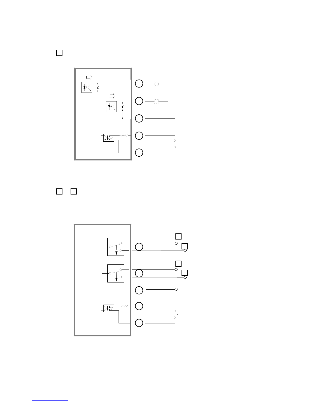
10-5. Interface converter U-3B (Option )
Interface converter convert the electronic signal by opto coupler to opposite direction
as below.
Also it provide additional dry contact signals in both Normal Closed and Normal Open
by the built-in relay
OUT
Interface converter U-3B (ECA5914)
Size 75 x 60 x 28mm (h)
Weight 103gr
Opto coupler 12-24V 10mA max
Relay contact 30VDC 1A max
IN (from FT-40D)
Relay power off
when not use
Standard accessory cables
RJ-45 8PIN 2m long
RJ-45 8PIN 1.5m long
Run
Torque
UP
FT-40D
Spare
Spare
Opto
coupler RELAY
signal
N.C N.O
1
2
3
No Color Interface Signal FT-40D U-3B Interface converter I/O port
1ORANGE Spare
2ORANGE STRIPE Torque Up
3BLUE Motor Run
4BLUE STRIPE Common for 2&3 wire
5GREEN Motor Lock or
Remote Start
6GREEN STRIPE
7BROWN No use
8BROWN STRIPE Spare
8PIN Configuration and Output
1 2 3
- 9 -
■U-3B interface converter I/O details
1Opto-coupler port
2&3Relay N.C &N.O port
DRIVER LOCK or
REMOTE START ("A" option driver)
U-3B
START (motor run)
TORQUE UP
2
3
4
5
6
12V return
IN
PC817
PC817
12-24VDC(+) 10mA
OUT
DRIVER LOCK or
REMOTE START ("A" option driver)
U-3B
START (motor run)
TORQUE UP
2
3
4
5
6
Relay COM
IN
OUT
max 1A
Normal Closed
Normal Open
Normal Open
2
2
Normal Closed
3
3

- 10 -
Model Screw Start Torque
Kgf.cm Speed(RPM) Weight
Kg Controller Bit
Min Max
NF150 M2.6~M4
Lever
3~15 800 1700
0.52 KT-40DHex 5mm
Hex 1/4"
NF220 M3~M5 6~22 600 1250
NF450 M3~M6 7~45 300 650
NF150P M2.6~M4
PUSH
3~15 800 1700
NF220P M3~M5 6~22 600 1250
NF450P M3~M6 7~45 300 650
■Torque data are obtained at no load Max. speed.
■No load Min speeds are for Speed control option models.
■Torque at the same setting can be different according to the speed
■Standard packing -Screwdriver,Cable,Two demonstration bits,Manual
11. Screwdriver Specification
Type Model Start Torque
(Kgf.cm) No load speed
(rpm) Bit size Weight
(Kg) Voltage
Mini Fseries
Speed
control F035 LEVER 0.3~3.5 300~1,100 E: 4mm 0.24 DC30V
F045 0.5~4.5 300~700
Fseries
Speed
control
+
Soft start
F060 LEVER 1~6 700 ~ 1600
E: 4mm
A:Hex1/4" 0.41 DC30V
F080 1~8 500 ~ 1000
F120 2~12 300 ~ 700
F060P PUSH 1~6 700 ~ 1600
F080P 1~8 500 ~ 1000
F120P 2~12 300 ~ 700
Soft start
+
Double hit
(+ option)
F060+ LEVER 1~6 700 ~ 1600
F080+ 1~8 500 ~ 1000
F120+ 2~12 300 ~ 700
Angle control
+
Auto reverse
FT060 LEVER 1~6 700 ~ 1600
FT080 1~8 500 ~ 1000
FT120 2~12 300 ~ 700
LF series
Single speed
LF060
LEVER
1~6 1,550
E: 4mm
A:Hex1/4"
B:Hex5mm
0.44 DC30V
LF080 2~8 1,250
LF120 3~12 1,000
LF180 4~18 700
LF080P
PUSH
1~6 1,550
LF080P 2~8 1,250
LF120P 3~12 1,000
LF180P 4~18 700
NF series
Speed
control
+
Soft start
NF150
LEVER
3~15 800~1700
A:Hex1/4"
or
B:Hex5mm
0.52 DC40V
NF220 6~22 600~1250
NF350 6~35 400~800
NF450 7~45 300~650
NF150P
PUSH
3~15 800~1700
NF220P 6~22 600~1250
NF350 6~35 400~800
NF450P 7~45 300~650
Soft start
+
Double hit
NF150
LEVER
3~15 800~1700
NF220 6~22 600~1250
NF350 6~35 400~800
NF450 7~45 300~650
Angle control
&Auto reverse
NFT150
LEVER
3~15 800~1700
NFT220 6~22 600~1250
NF350 6~35 400~800
NFT450 7~45 300~650
- 11 -
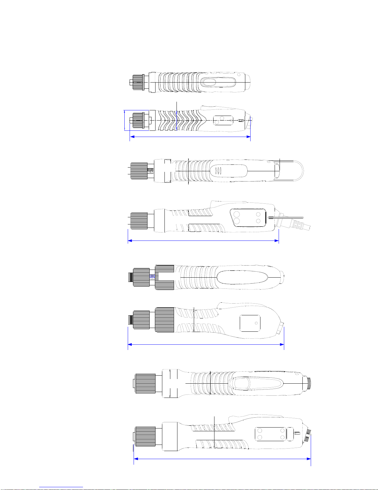
12. Screwdriver Dimensions
195
Ø30
Ø32
Ø33
258
Ø34.3
Ø41.6
■Mini Fseries
228
Ø31
Ø35.4
Ø32.8
■Mini Fseries
■Mini Fseries
■Mini Fseries
230
Ø32
Ø38.4
- 12 -
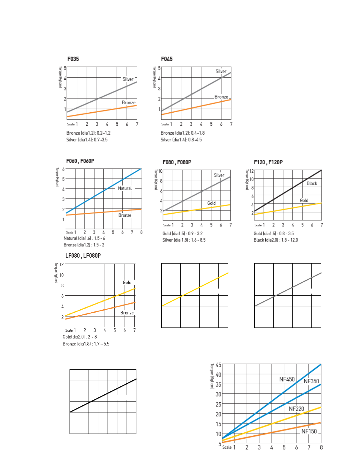
13. Torque curve (at No load Max. speed)
LF120, LF120P
1234567
scale
Gold (dia2.0) : 4 - 10 Kgf.cm
12
10
8
6
4
2
Torque Kgf.cm
Gold
LF180, LF180P
1234567
scale
Silver (dia2.1) : 4 - 15 Kgf.cm
18
15
12
9
6
3
Torque Kgf.cm
Silver
LF250, LF250P
1234567
scale
Black (dia2.2) : 7 - 20 Kgf.cm
24
20
16
12
8
4
Torque Kgf.cm
Black
NF150, NF220, NF350, NF450

- 13 -
14. Panel of each model
■Standard
■Soft start &Double hit (+option )
■Angle control &Auto reverse (Toption )
15. Alarm display by LED
no Alarm Description Reset
1Over Voltage (over 44V) ●●↔●● Green &Red lights blinks Auto reset under 44V
2Overload (4A/0.5s) ●● Two Red lights blinks. Auto reset after 5s
3Overheat(over 80℃_motor) ●● Two Orange light blinks Auto reset lower than 80℃
4Driver Lock by ext. signal ●● Two Green lights blinks Auto reset by signal off

- 14 -
16. Operation
16.1 Speed change in standard model
■Speed display by two LED color (Standard model)
16.2 Soft start &Double hit (+option )
The Plus option drivers have the single speed of the maximum in the speed range.
■Double Hit
When "Double Hit" is chosen by the Double Hit button, LED Awill light Orange color.
During the motor run, LED Awill display Green light.
Model LED ●● ●●●●●●●● ●● ● ●●●●●
Button 1th 2nd 3rd 4th 5th 6th 7th 8th 9th
F060 RPM 650 750 850 950 1,050 1150 1250 1350 1500
F080 RPM 380 450 520 580 640 700 780 850 950
F120 RPM 300 350 395 440 480 535 590 625 690
NF150 RPM 800 900 1,000 1,100 1,200 1,300 1,400 1,500 1,700
NF220 RPM 600 650 700 750 800 900 1000 1100 1250
NF350 RPM 400 450 500 550 600 650 700 750 800
NF450 RPM 300 340 380 415 450 490 530 565 600
1) Keep pressing the Speed button for 2second to visit
to PROGRAM mode. Then two LED lights will display
the set speed.
2) Select "Reverse" of F/R switch for increasing speed.
or select "Forward" of F/R switch for increasing speed.
3) Press "Speed" button and select the target speed.
The set speed can be recognized by the colors of
two LED as below
4) By operating screwdriver, it goes back to operating
(work) mode.
speed
Increase speed
Decrease
2
13
LED- A
LED- B
■Soft Start
The rotation speed reaches to the target speed
gradually after the soft start time as below.
●Green : 0.2 second
●Red : 0.4 second
●Orange : 0.6 second

- 15 -
16.3 Angle control &Auto reverse (Toption )
One triggering by the lever can make 3step operation sequence in acycle
■Start, Stop and Direction in acycle
Step 1→2→3
Sequence first RUN stop HOLD reverse RUN
Rotating
direction
Clockwise or
Counterclockwise
by F/R switch Reverse
Activating
Screwdriver run and
stop at the target
angle when the angle
is set. It always stop
at the set torque,
even it does not
reach to the target
angle.
delay for set
time
Rotate reverse untill
releasing the lever or
stop at the target
torque
Angle run
&
Time
delay
24 steps
1/4 to 15 turns 14 steps
0.2 to 3sec 24 steps
1/4 to 15 turns
-Screwdriver stops Immediately when the lever is released in any sequence.
-Sliding F/R switch works for
■Operating (Work) mode
①Rotating direction (FOR-REV)
■PROGRAM mode
①First run angle (Increase /Decrease) together with "First Run(Speed)" button
②Time (Increase /Decrease) together with "Stop(Reverse)" button
③Rotation speed (Increase /Decrease) together with "Speed(First Run)" button
④Reverse run angle (Increase /Decrease) together with "Reverse(Stop)" button
Increase Decrease
2
3
4
1

- 16 -
■Angle setting for first RUN
①Keep the first Run button pressed over 2sec. for angle setting.
Then press one by one for the desired rotating angle
②Select the Rposition of F/R switch for increasing set angle or Fposition
for decreasing set angle
③Keep the first Run button pressed over 2sec. for Lock &operating mode.
■Time setting for stop HOLD
①Keep the stop time button pressed over 2sec. Then click the stop time
button one by one for desired stop holding time
②Select the Rposition of F/R switch for increasing set time or Fposition
for decreasing set time
③Keep the stop time button pressed over 2sec. for Lock &operating mode.
Click 01
th 2nd 3rd 4th 5th 6th 7th 8th 9th 10th 11th 12th 13th 14th
Time
(second) Off 0 0.2 0.4 0.6 0.8 1 1.25 1.5 1.75 2 2.25 2.5 2.75 3
LED Orange RGRGRGRGRGRGRO
Click
╋
Keep pressed
over 2sec.
for Unlock &
Lock Increase Decrease
Click
╋
Keep pressed
over 2sec.
for Unlock &
Lock
Increase Decrease
Click 01
st 2
nd 3
rd 4
th 5
th 6
th 7
th 8
th 9
th 1
01
11
21
31
41
51
61
71
81
92
02
12
22
32
42
52
62
72
82
9
Turns Off 1
42
43
415
46
47
429
41
0
4
1
1
434567891
01
21
41
61
82
02
22
42
62
83
0
LED O RGRGRGRGRGRGRGRGRGRGRGRGRGRGO

- 17 -
■Rotating speed setting
①Keep the both first Run &stop time buttons pressed over 2sec. for unlock.
Then click one by one for the desired rotating speed.
②Select the Rposition of F/R switch for increasing speed or Fposition for
decreasing speed
③Keep the first Run button pressed over 2sec. for Lock &operating mode.
※Refer the Speed display by LED on page 14. / Standard driver speed display
■Angle setting for Reverse RUN
①Keep the both first Run &stop time buttons pressed over 2sec. for unlock.
Then click stop time button one by one for the desired angle
②Select the Rposition of F/R switch for increasing set angle or Fposition
for decreasing set angle
③Keep the stop time button pressed over 2sec. for Lock &operating mode.
Keep 2buttons
pressed over 2
sec. for
Unlock &Lock Click
╋
Increase Decrease
Keep 2buttons
pressed over 2
sec. for
Unlock &Lock Click
╋
Increase Decrease
Click 01
st 2
nd 3
rd 4
th 5
th 6
th 7
th 8
th 9
th 1
01
11
21
31
41
51
61
71
81
92
02
12
22
32
42
52
62
72
82
9
Turns Off 1
42
43
415
46
47
429
41
0
4
1
1
434567891
01
21
41
61
82
02
22
42
62
83
0
LED O RGRGRGRGRGRGRGRGRGRGRGRGRGRGO

- 18 -
■Application Example
first
RUN
Angle
stop
HOLD
Time
Auto
Reverse
Angle
Applications with different
sequence in acycle
Normal
screwdriver off off off Normal screwdriver
It stops at the set torque
Angle
control ON(1) off off It stops at set angle(1)
Tapper
or
Insert
fastening
ON(1) ON(2) ON(3)
or
OFF
It stops at set angle(1) and
waits for set time(2), and makes
reverse rotation to the set
angle(3) or until the lever is
released
Wire
inserting
on terminal
block
ON(1) ON(2) OFF
It stops at set angle(1) and
waits for set time(2), and makes
reverse rotation and stops at set
torque
This manual suits for next models
3
Table of contents
Other Sehan Electools Power Screwdriver manuals

Popular Power Screwdriver manuals by other brands

Parkside
Parkside PAWS 3.6 A1 original operation manual

Bosch
Bosch AdvancedImpactDrive 18 Original instructions

Makita
Makita DDA351RMJ instruction manual

EINHELL
EINHELL KSS12/2 Operating and maintenance instructions

Festool
Festool C 12 Li Original operating manual and Spare parts list

Pattfield
Pattfield PE-36B Original instructions


